Difference between revisions of "NanoPC-T4/zh"
From FriendlyELEC WiKi
(→烧写系统到eMMC) |
(→烧写系统到eMMC) |
||
| Line 450: | Line 450: | ||
===烧写系统到eMMC=== | ===烧写系统到eMMC=== | ||
FriendlyELEC推出的基于RK3399的开发板,支持3种方式烧写系统到eMMC: | FriendlyELEC推出的基于RK3399的开发板,支持3种方式烧写系统到eMMC: | ||
| − | * | + | * 用eflasher固件制作SD启动卡并启动后脱机烧写 |
| − | * | + | * 用Rockchip提供的Windows下的AndroidTool_Release_v2.42,通过Type-C数据线连机烧写 |
| − | * | + | * 用Rockchip提供的Linux_Upgrade_Tool_1.27,通过Type-C数据线烧写 |
如果您没有Type-C数据线,或不太熟悉Rockchip提供的工具,建议采用第一种方式即SD卡启动脱机烧写的方式。 | 如果您没有Type-C数据线,或不太熟悉Rockchip提供的工具,建议采用第一种方式即SD卡启动脱机烧写的方式。 | ||
====下载固件及工具==== | ====下载固件及工具==== | ||
| − | 首先访问[http://dl.friendlyarm.com/NanoPC-T4 此处的下载地址] | + | 首先访问[http://dl.friendlyarm.com/NanoPC-T4 此处的下载地址]下载需要的固件文件及工具:<br /> |
| − | + | ||
{| class="wikitable" | {| class="wikitable" | ||
|- | |- | ||
Revision as of 09:06, 2 June 2018
Contents
1 介绍
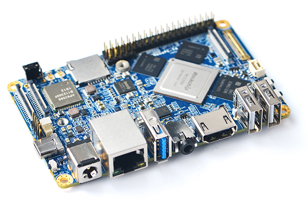
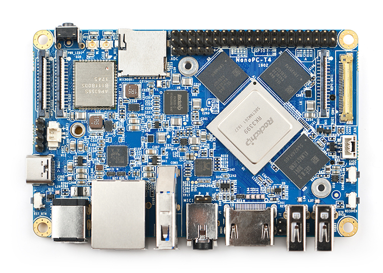
- NanoPC-T4不仅是世界上最小的全功能接口RK3399一体化主板, 而且是一款完全开源的高性能计算平台。它的尺寸只有100x64mm,标配4GB LPDDR3内存和16GB闪存, 板载2.4G & 5G双频WiFi模组, 带有标准完整的M.2 PCIe接口, 可直接安装使用NVME SSD高速固态硬盘。NanoPC-T4支持运行Android 7.1和Lubuntu Desktop两种系统,它们均带有GPU和VPU加速处理。
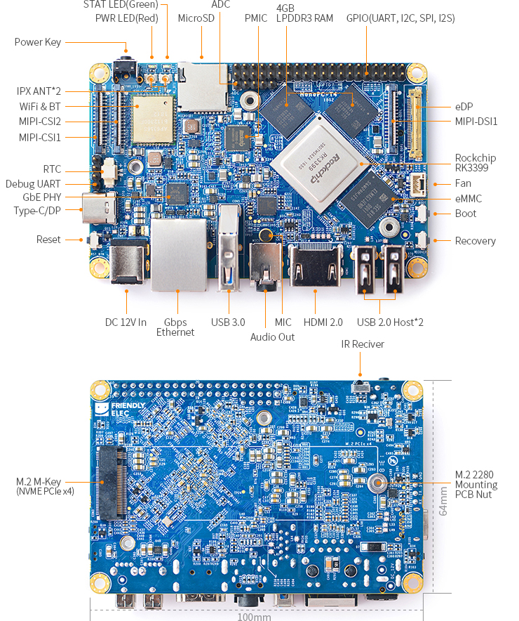
- NanoPC-T4还带有MIPI-CSI双摄像头接口, MIPI-DSI和eDP双显示接口, HDMI 2.0视频输出口,并具备Type-C/DP,USB 3.0, USB2.0,MicroSD, 千兆以太网口,3.5mm音频输出口,红外接收等常见标准接口,以及AD输入,调试串口,40Pin树莓派兼容扩展口。
- RK3399内置新一代高端图像处理器Mali-T860, 具有超强的3D处理和超高清H.265/H2.64视频解析能力,并可支持双路摄像头同时输入,双ISP像素处理能力高达800MPix/s。NanoPC-T4非常适合广告机,游戏主机,视频会议,智能监控,集群计算,虚拟现实,机器视觉和计算机视觉等方面的应用,并且是人工智能和深度学习平台的绝佳选择!
2 硬件特性
- 主控芯片: Rockchip RK3399
- CPU: big.LITTLE大小核架构,双Cortex-A72大核(up to 2.0GHz)+四Cortex-A53小核结构(up to 1.5GHz)
- GPU: Mali-T864 GPU,支持OpenGL ES1.1/2.0/3.0/3.1, OpenVG1.1, OpenCL, DX11, 支持AFBC(帧缓冲压缩)
- VPU: 支持4K VP9 and 4K 10bits H265/H264 视频解码,高达60fps, 双VOP显示等视频编解码功能
- 电源管理单元: RK808-D PMIC, 搭配独立DC/DC, 支持动态调压, 软件关机, 按键开机, RTC唤醒, 睡眠唤醒等功能
- 内存: 双通道4GB LPDDR3-1866
- Flash: 16GB eMMC 5.1 Flash
- 有线网络: 原生千兆以太网
- Wi-Fi/蓝牙: 802.11a/b/g/n/ac, Bluetooth 4.1 双频Wi-Fi蓝牙模块, 双天线
- 视频输入: 2个4线MIPI-CSI, 双ISP像素处理能力高达13MPix/s,支持双路摄像头数据同时输入
- 视频输出
- HDMI: HDMI 2.0a, 支持4K@60Hz显示,支持HDCP 1.4/2.2
- DP on Type-C: DisplayPort 1.2 Alt Mode on USB Type-C
- LCD Interface: 一个eDP 1.3(4 线,10.8Gbps), 一个4线MIPI-DSI
- Audio Out: 3.5mm 双通道耳机接口, 或者通过HDMI输出
- Audio In: 板载麦克风
- USB 2.0: 2个独立的原生USB 2.0 Host A型接口
- USB 3.0: 1个原生USB 3.0 Host A型接口
- USB Type-C: 支持USB3.0 Type-C 和 DisplayPort 1.2 Alt Mode on USB Type-C
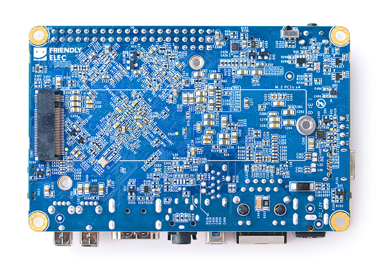
- PCIe: 一个 M.2 M-Key PCIe x4 接口, 兼容PCIe 2.1, 双操作模式, 带有M.2 2280模块M3固定螺柱
- microSD Slot x 1
- 40Pin GPIO 扩展接口:
- 1 X 3V/1.8V I2C, up to 2 x 3V UART, 1 X 3V SPI, 1 x SPDIF_TX, up to 8 x 3V GPIOs
- 1 x 1.8V I2S, 3 x 1.8V GPIOs
- ADC: 提供3路 1.8V ADC 输入, 5 Pin 2.54mm 排针接口
- 调试串口: 4 Pin 2.54mm 调试串口, 3V电平, 波特率为1500000
- 按键: 电源按键, 复位按键, MASKROM按键(BOOT), 系统还原按键
- LED: 1 x power LED and 1 x GPIO Controled LED
- 红外接收器: 板载红外接收器, 接受的载波频率为38KHz
- RTC电池座子: 2 Pin 1.27/1.25mm RTC备份电池接口
- 散热片和风扇: 2个2.5mm焊接螺柱, 专门用于固定散热片; 3 Pin 12V 支持PWM调节的风扇接口
- 供电电源: DC 12V/2A
- PCB: Ten Layer, 100 mm x 64 mm
- 环境工作温度: 0℃ to 80℃
3 接口布局和尺寸
3.1 接口布局
- 40 Pin GPIO引脚定义
Pin# Assignment Pin# Assignment 1 VCC3V3_SYS 2 VCC5V0_SYS 3 I2C2_SDA(3V) 4 VCC5V0_SYS 5 I2C2_SCL(3V) 6 GND 7 GPIO1_A0(3V) 8 UART2B_TX(3V) 9 GND 10 UART2B_RX(3V) 11 GPIO1_A1(3V) 12 GPIO1_C2(3V) 13 GPIO1_A3(3V) 14 GND 15 GPIO1_A4(3V) 16 GPIO1_C6(3V) 17 VCC3V3_SYS 18 GPIO1_C7(3V) 19 SPI1_TXD/UART4_TX(3V) 20 GND 21 SPI1_RXD/UART4_RX(3V) 22 GPIO1_D0(3V) 23 SPI1_CLK(3V) 24 SPI1_CSn0(3V) 25 GND 26 GPIO4_C5/SPDIF_TX(3V) 27 I2C2_SDA(1.8V) 28 I2C2_SCL(1.8V) 29 I2S1_LRCK_RX(1.8V) 30 GND 31 I2S1_LRCK_TX(1.8V) 32 I2S_CLK(1.8V) 33 I2S1_SCLK(1.8V) 34 GND 35 I2S1_SDI0(1.8V) 36 I2S1_SDO0(1.8V) 37 GPIO3_D4(1.8V) 38 GPIO3_D5(1.8V) 39 GND 40 GPIO3_D6(1.8V)
- eDP接口引脚定义
- 连接器型号: I-PEX-20455-030E
Pin# Assignment Description 1 GND Signal ground 2 EDP_TX3N eDP data lane 3 negative output 3 EDP_TX3P eDP data lane 3 positive output 4 GND Signal ground 5 EDP_TX2N eDP data lane 2 negative output 6 EDP_TX2P eDP data lane 2 positive output 7 GND Signal ground 8 EDP_TX1N eDP data lane 1 negative output 9 EDP_TX1P eDP data lane 1 positive output 10 GND Signal ground 11 EDP_TX0N eDP data lane 0 negative output 12 EDP_TX0P eDP data lane 0 positive output 13 GND Signal ground 14 EDPAUXP eDP CH-AUX positive differential output 15 EDPAUXN eDP CH-AUX negative differential output 16 GND Signal ground 17 VCC3V3_SYS 3.3V Power output for logic 18 VCC3V3_SYS 3.3V Power output for logic 19 I2C4_SDA 3V I2C data signal, Connect to touch panel 20 I2C4_SCL 3V I2C clock signal, Connect to touch panel 21 GPIO1_C4_TP_INT 3V interrupt input, Connect to the interrupt output of touch panel 22 GPIO1_B5_TP_RST 3V output for reseting touch panel, Connect to the reset input of touch panel 23 PWM0_BL 3V PWM output, for LCD backlight dimming 24 GPIO4_D5_LCD_BL_EN 3V output for turning on/off the LCD backlight 25 GND Backlight ground 26 GND Backlight ground 27 GND Backlight ground 28 VCC12V0_SYS 12V Power output for Backlight Power 29 VCC12V0_SYS 12V Power output for Backlight Power 30 VCC12V0_SYS 12V Power output for Backlight Power
- MIPI-DSI接口引脚定义
- 0.5mm FPC 连接器
Pin# Assignment Description 1, 2, 3 VCC5V0_SYS 5V power output 4 GND Return current path 5 I2C4_SDA 3V I2C data signal, Connect to touch panel 6 I2C4_SCL 3V I2C clock signal, Connect to touch panel 7 GND Return current path 8 GPIO1_C4_TP_INT 3V interrupt input, Connect to the interrupt output of touch panel 9 GND Return current path 10 PWM0_BL 3V PWM output, for LCD backlight dimming 11 GND Return current path 12 GPIO4_D5_LCD_BL_EN 3V output for turning on/off the LCD backlight 13 GPIO4_D6_LCD_RST_H 3V output for reseting the LCD module 14 GPIO1_B5_TP_RST 3V output for reseting touch panel, Connect to the reset input of touch panel 15 GND Return current path 16 MIPI_TX0_D3N MIPI DSI negative differential data line transceiver output 17 MIPI_TX0_D3P MIPI DSI positive differential data line transceiver output 18 GND Return current path 19 MIPI_TX0_D2N MIPI DSI negative differential data line transceiver output 20 MIPI_TX0_D2P MIPI DSI positive differential data line transceiver output 21 GND Return current path 22 MIPI_TX0_D1N MIPI DSI negative differential data line transceiver output 23 MIPI_TX0_D1P MIPI DSI positive differential data line transceiver output 24 GND Return current path 25 MIPI_TX0_D0N MIPI DSI negative differential data line transceiver output 26 MIPI_TX0_D0P MIPI DSI positive differential data line transceiver output 27 GND Return current path 28 MIPI_TX0_CLKN MIPI DSI negative differential clock line transceiver output 29 MIPI_TX0_CLKP MIPI DSI positive differential clock line transceiver output 30 GND Return current path
- MIPI-CSI接口引脚定义
- 0.5mm FPC 连接器
Pin# MIPI-CSI1 MIPI-CSI2 Description 1 VCC5V0_SYS VCC5V0_SYS 5V Power ouput 2 VCC5V0_SYS VCC5V0_SYS 5V Power ouput 3 GND GND Return current path 4 VCC_CSI_AF2.8V VCC_CSI_AF2.8V 2.8V Power for VCM 5 VCC_CSI_1.2V VCC_CSI_1.2V 1.2V Power for image sensor core circuit 6 VCC1V8_CAM VCC1V8_CAM 1.8V power for I/O circuit 7 VCC_CSI_2.8V VCC_CSI_2.8V 2.8V power for image sensor analog circuit 8 VCC_CSI_1.0V VCC_CSI_1.0V 1.0V Power for image sensor core circuit 9 I2C1_SCL I2C2_SCL 1.8V I2C clock signal 10 I2C1_SDA I2C2_SDA 1.8V I2C data signal 11 MIPI_CSI0_RST MIPI_CSI1_RST reset camera module 12 MIPI_CSI0_PWN MIPI_CSI1_PWN Power down camera module 13 GND GND Return current path 14 GPIO2_B3_CIF_CLKOUTA GPIO2_B3_CIF_CLKOUTA MCLK to camera module 15 GND GND Return current path 16 MIPI_RX0_D3P MIPI_TX1/RX1_D3P MIPI CSI positive differential data line transceiver output 17 MIPI_RX0_D3N MIPI_TX1/RX1_D3N MIPI CSI negative differential data line transceiver output 18 GND GND Return current path 19 MIPI_RX0_D2P MIPI_TX1/RX1_D2P MIPI CSI positive differential data line transceiver output 20 MIPI_RX0_D2N MIPI_TX1/RX1_D2N MIPI CSI negative differential data line transceiver output 21 GND GND Return current path 22 MIPI_RX0_D1P MIPI_TX1/RX1_D1P MIPI CSI positive differential data line transceiver output 23 MIPI_RX0_D1N MIPI_TX1/RX1_D1N MIPI CSI negative differential data line transceiver output 24 GND GND Return current path 25 MIPI_RX0_CLKP MIPI_TX1/RX1_CLKP MIPI CSI positive differential clock line transceiver output 26 MIPI_RX0_CLKN MIPI_TX1/RX1_CLKN MIPI CSI negative differential clock line transceiver output 27 GND GND Return current path 28 MIPI_RX0_D0P MIPI_TX1/RX1_D0P MIPI CSI positive differential data line transceiver output 29 MIPI_RX0_D0N MIPI_TX1/RX1_D0N MIPI CSI negative differential data line transceiver output 30 GND GND Return current path
- M.2 PCIe接口引脚定义
- PCIe Gen 2.1 x4
- M.2 Key M Connector for Socket 2/Socket 3 PCIe-based Module, such as PCIe SSD
- 连接器型号: MDT-420-M-01002
Pin# Assignment Description Pin# Assignment Description 1 GND Return current path 2 VCC3V3_SYS 3.3V Power output 3 GND Return current path 4 VCC3V3_SYS 3.3V Power output 5 PCIE_RX3_N PCIe differential data input signals 6 N/C no connection 7 PCIE_RX3_P PCIe differential data input signals 8 N/C no connection 9 GND Return current path 10 N/C no connection 11 PCIE_TX3N PCIe differential data output signals 12 VCC3V3_SYS 3.3V Power output 13 PCIE_TX3P PCIe differential data output signals 14 VCC3V3_SYS 3.3V Power output 15 GND Return current path 16 VCC3V3_SYS 3.3V Power output 17 PCIE_RX2_N PCIe differential data input signals 18 VCC3V3_SYS 3.3V Power output 19 PCIE_RX2_P PCIe differential data input signals 20 N/C no connection 21 GND Return current path 22 N/C no connection 23 PCIE_TX2N PCIe differential data output signals 24 N/C no connection 25 PCIE_TX2P PCIe differential data output signals 26 N/C no connection 27 GND Return current path 28 N/C no connection 29 PCIE_RX1_N PCIe differential data input signals 30 N/C no connection 31 PCIE_RX1_P PCIe differential data input signals 32 N/C no connection 33 GND Return current path 34 N/C no connection 35 PCIE_TX1N PCIe differential data output signals 36 N/C no connection 37 PCIE_TX1P PCIe differential data output signals 38 DEVSLP/NC internal pull up to VCC3V3_SYS with 10K 39 GND Return current path 40 I2C2_SCL 1.8V I2C clock signal 41 PCIE_RX0_N PCIe differential data input signals 42 I2C2_SDA 1.8V I2C data signal 43 PCIE_RX0_P PCIe differential data input signals 44 GPIO2_A2_PCIE_ALERT# 1.8V GPIO signal 45 GND Return current path 46 N/C no connection 47 PCIE_TX0N PCIe differential data output signals 48 N/C no connection 49 PCIE_TX0P PCIe differential data output signals 50 GPIO2_A4_PCIE_RESET# 1.8V GPIO signal 51 GND Return current path 52 CLKREQ#/NC internal pull down to GND with 0R 53 PCIE_REF_CLKN differential reference clock out for PCIe peripheral 54 GPIO2_A3_PCIE_WAKE# 1.8V GPIO signal 55 PCIE_REF_CLKP differential reference clock out for PCIe peripheral 56 N/C no connection 57 GND Return current path 58 N/C no connection 59 Connector Key Connector Key 60 Connector Key Connector Key 60 Connector Key Connector Key 61 Connector Key Connector Key 62 Connector Key Connector Key 63 Connector Key Connector Key 64 Connector Key Connector Key 65 Connector Key Connector Key 66 Connector Key Connector Key 67 N/C no connection 68 RTC_CLKO_SOC 1.8V 32.768KHz clock output 69 N/C no connection 70 VCC3V3_SYS 3.3V Power output 71 GND Return current path 72 VCC3V3_SYS 3.3V Power output 73 GND Return current path 74 VCC3V3_SYS 3.3V Power output 75 GND Return current path
- ADC接口引脚定义
- ADC输入范围 : 0~1.8V
Pin# Assignment 1 GND 2 VCC_1V8 3 ADC_IN0 4 ADC_IN2 5 ADC_IN3
- 散热风扇接口引脚定义
- 连接器型号: BM03B-GHS-TBT
Pin# Assignment Description 1 GND 0V 2 12V 12V output ,controlled by GPIO4_C6/PWM1 3 GPIO2_A6_FAN_TACH connect to tachometer output signal , or float
- 调试串口引脚定义
- 3V电平, 波特率1500000bps
Pin# Assignment Description 1 GND 0V 2 VCC5V0_SYS 5V power output 3 UART2DBG_TX output 4 UART2DBG_RX intput
- 电源接口
- 电源按键
- 插入电源后, 需要按一下电源按键T4才会开机.
- 当板子处于关机或睡眠状态时, 按一下电源按键, 板子就会被唤醒.
- USB接口
- USB Type-C 接口具有2A过流保护功能.
- USB 3.0 接口具有2A过流保护功能.
- 两个USB 2.0接口共享2A过流保护, 也就是说2个接口的负载总和不应超过2A, 否则触发保护, 2个接口上的设备都会被切断电源.
- BOOT按键
- 按下BOOT按键可以阻止板子从eMMC启动系统; 当板子无法从eMMC和tf卡启动系统时, 板子就会进入MASKROM模式; MASKROM模式下, 可以通过Type-C接口更新板子的系统.
- RTC
- 我们实测的RTC备份电流为27uA.
- 其他说明
- 只能从DC电源接口给板子供电, 其他接口的电源引脚均为输出引脚.
- 板子原理图: NanoPC-T4-1802-Schematic.pdf
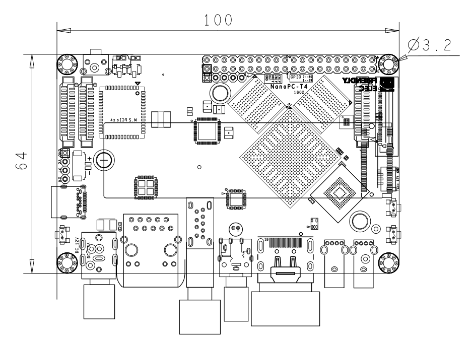
3.2 尺寸
- PCB dxf文件, 仅供做产品时结构设计使用: NanoPC-T4_1802_Drawing(dxf).zip
4 快速入门
4.1 准备工作
要开启你的NanoPC-T4,请先准备好以下硬件:
- NanoPC-T4主板
- Type-C数据线
- TF卡: Class10或以上的8GB microSD卡
- USB转串口适配器(可选,用于调试或PC上进行操作)
- 一个DC接口的外接电源,要求输出为12V/2A
- 一台支持HDMI输入的显示器或者电视(或选购LCD配件)
- 一套USB键盘鼠标,同时连接更多USB的设备时还需要USB HUB
- 一台电脑,需要联网,建议使用Ubuntu 14.04 64位系统,或Windows 7以上
4.2 烧写系统到eMMC
FriendlyELEC推出的基于RK3399的开发板,支持3种方式烧写系统到eMMC:
- 用eflasher固件制作SD启动卡并启动后脱机烧写
- 用Rockchip提供的Windows下的AndroidTool_Release_v2.42,通过Type-C数据线连机烧写
- 用Rockchip提供的Linux_Upgrade_Tool_1.27,通过Type-C数据线烧写
如果您没有Type-C数据线,或不太熟悉Rockchip提供的工具,建议采用第一种方式即SD卡启动脱机烧写的方式。
4.2.1 下载固件及工具
首先访问此处的下载地址下载需要的固件文件及工具:
| Image Files | |
| rk3399-eflasher-YYYYMMDD-full.img.zip | SD卡映象,用于SD启动后脱机烧写Android或lubuntu系统到eMMC |
| android-nougat-images.tgz | Android 7.1.2固件 |
| lubuntu-desktop-images.tgz | LUbuntu桌面版固件,自带X Window图形界面 |
| Flash Utility: | |
| win32diskimager.rar | Windows utility. Under Linux users can use "dd" |
| AndroidTool_Release_v2.42.7z | Rockchip提供的Windows下的通过Type-C数据线烧写系统的工具 |
| DriverAssitant_v4.5.tgz | Rockchip提供的Windows下的USB驱动,使用AndroidTool烧写系统时需要安装此驱动 |
| Linux_Upgrade_Tool_1.27.rar | Rockchip提供的Linux下的通过Type-C数据线更新系统的工具 |
