Difference between revisions of "BakeBit - Light Sensor"
| (8 intermediate revisions by the same user not shown) | |||
| Line 1: | Line 1: | ||
[[BakeBit - Light Sensor/zh|查看中文]] | [[BakeBit - Light Sensor/zh|查看中文]] | ||
| − | == | + | ==Introduction== |
[[File:BakeBit - Light Sensor.jpg|thumb|Light Sensor]] | [[File:BakeBit - Light Sensor.jpg|thumb|Light Sensor]] | ||
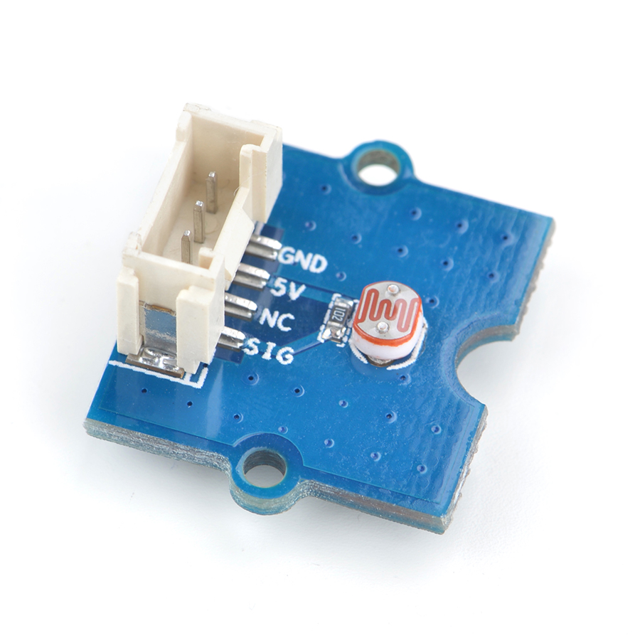
| − | *BakeBit - Light | + | * The BakeBit - Light Sensor is a photoresistor module. The resistance of a photoresistor decreases with increasing incident light intensity. |
| − | * | + | * If incident light on a photoresistor exceeds a certain frequency, photons absorbed by the semiconductor give bound electrons enough energy to jump into the conduction band. The resulting free electrons (and their hole partners) conduct electricity, thereby lowering resistance. |
| − | == | + | ==Hardware Spec== |
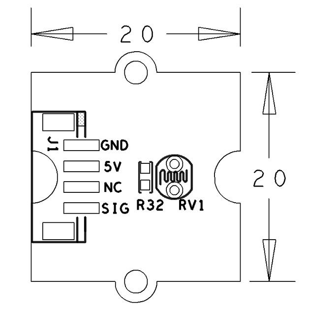
| − | * | + | * Standard 2.0mm pitch 4-Pin BakeBit Interface |
| − | * | + | * PCB dimension(mm): 20 x 24 |
| − | * | + | * Analog Outpu |
[[File:BakeBit - Light Sensor_PCB.png | frameless|350px|BakeBit - Light Sensor]] | [[File:BakeBit - Light Sensor_PCB.png | frameless|350px|BakeBit - Light Sensor]] | ||
| − | * | + | * Pin Description: |
{| class="wikitable" | {| class="wikitable" | ||
|- | |- | ||
| − | | | + | |Pin || Description |
|- | |- | ||
| − | |GND || | + | |GND || Ground |
|- | |- | ||
| − | |5V || | + | |5V || 5V Supply Voltage |
|- | |- | ||
| − | |NC || | + | |NC || Ground |
|- | |- | ||
| − | |SIG || | + | |SIG || Signal |
|} | |} | ||
| − | |||
| − | + | == Code Sample: Smart Lighting == | |
| − | + | ||
| − | === | + | By running this code sample your system adjusts the LEDs on the LED module(LED Bar) according to surrounding lightness. When the surrounding environment becomes darker the LEDs will be brighter. When the surrounding becomes bright enough the LEDs will be completely off. |
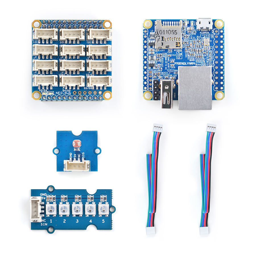
| − | + | A [[BakeBit - LED Bar]] module is needed in this test case. | |
| + | |||
| + | === Hardware Setup === | ||
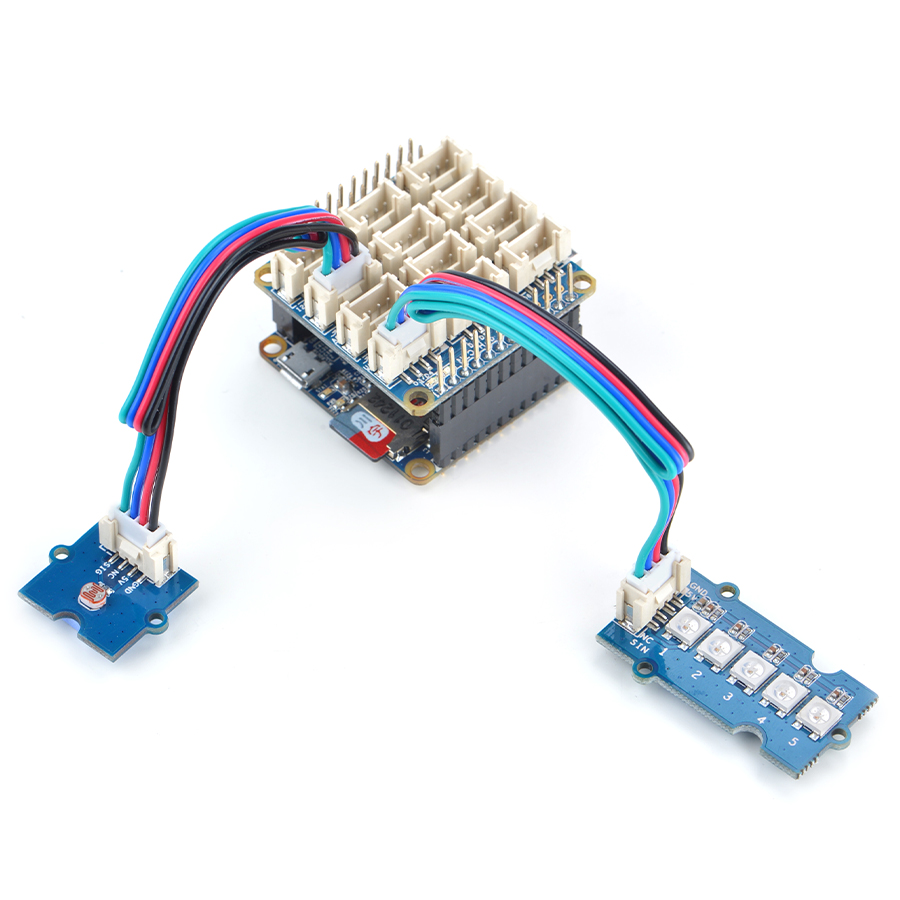
| + | Connect the [[BakeBit - LED Bar]] module to the NanoHat Hub's D3 and the [[BakeBit - Light Sensor]] module to the NanoHat Hub's A0: | ||
::{| class="wikitable" | ::{| class="wikitable" | ||
| Line 39: | Line 40: | ||
|} | |} | ||
| − | === | + | === Source Code === |
<syntaxhighlight lang="python"> | <syntaxhighlight lang="python"> | ||
| Line 114: | Line 115: | ||
| − | === | + | === Run Code Sample === |
| − | + | Before you run the code sample you need to follow the steps in [http://wiki.friendlyarm.com/bakebit bakebit tutorial] to install the BakeBit package.<br /> | |
| − | + | Enter the "BakeBit/Software/Python" directory and run the "bakebit_prj_SmartLighting.py" program: | |
<syntaxhighlight lang="bash"> | <syntaxhighlight lang="bash"> | ||
cd ~/BakeBit/Software/Python | cd ~/BakeBit/Software/Python | ||
| Line 123: | Line 124: | ||
</syntaxhighlight> | </syntaxhighlight> | ||
| − | === | + | === Observation === |
| − | + | When you cover the smart lighting’s photo sensor or make the surrounding environment brighter the LEDs will be on or off.<br /> | |
| − | LED | + | The LEDs on the LED Bar module will be turned on or off according to surrounding environment’s lightness. When the the surrounding environment becomes darker more LEDs will be turned on otherwise the LEDs will be off. |
| − | == | + | ==Resources== |
*[Schematic]([http://wiki.friendlyarm.com/wiki/images/e/e8/06-SCHEMATIC_Light_Sensor.pdf BakeBit - Light Sensor.pdf]) | *[Schematic]([http://wiki.friendlyarm.com/wiki/images/e/e8/06-SCHEMATIC_Light_Sensor.pdf BakeBit - Light Sensor.pdf]) | ||
| − | *[BakeBit | + | *[BakeBit Github Project Page](https://github.com/friendlyarm/BakeBit) |
| − | *[BakeBit Starter | + | *[BakeBit Starter Kit User's Manual](http://wiki.friendlyarm.com/bakebit/bakebit_starter_kit_manual_en.pdf) |
| + | |||
| + | ==Update Log== | ||
| + | ===December-13-2016=== | ||
| + | * Released English version | ||
| + | |||
| + | ===Jan-19-2017=== | ||
| + | * Renamed "NEO-Hub" to "NanoHat-Hub" | ||
| + | |||
| + | ===Jan-20-2017=== | ||
| + | * Renamed "NanoHat-Hub" to "NanoHat Hub" | ||
Latest revision as of 08:17, 20 January 2017
Contents
1 Introduction
- The BakeBit - Light Sensor is a photoresistor module. The resistance of a photoresistor decreases with increasing incident light intensity.
- If incident light on a photoresistor exceeds a certain frequency, photons absorbed by the semiconductor give bound electrons enough energy to jump into the conduction band. The resulting free electrons (and their hole partners) conduct electricity, thereby lowering resistance.
2 Hardware Spec
- Standard 2.0mm pitch 4-Pin BakeBit Interface
- PCB dimension(mm): 20 x 24
- Analog Outpu
- Pin Description:
| Pin | Description |
| GND | Ground |
| 5V | 5V Supply Voltage |
| NC | Ground |
| SIG | Signal |
3 Code Sample: Smart Lighting
By running this code sample your system adjusts the LEDs on the LED module(LED Bar) according to surrounding lightness. When the surrounding environment becomes darker the LEDs will be brighter. When the surrounding becomes bright enough the LEDs will be completely off. A BakeBit - LED Bar module is needed in this test case.
3.1 Hardware Setup
Connect the BakeBit - LED Bar module to the NanoHat Hub's D3 and the BakeBit - Light Sensor module to the NanoHat Hub's A0:
3.2 Source Code
import time
import bakebit

# Connect the BakeBit Light Sensor to analog port A0
# SIG,NC,VCC,GND
light_sensor = 0

# Connect the BakeBit LED Bar to digital port D3
# DI,DCKI,VCC,GND
ledbar = 3


lowThreshold = 500
highTreshold = 600

bakebit.pinMode(light_sensor,"INPUT")
bakebit.pinMode(ledbar,"OUTPUT")
time.sleep(.2)
bakebit.bakeBitLedBar_Init(ledbar, 0, 5)
time.sleep(.5)
old_color = 0

while True:
    try:
        light_count = 0

        # Get sensor value
        sensor_value = bakebit.analogRead(light_sensor)
        if sensor_value > highTreshold:
            f=(1023-highTreshold)/4
            light_count =  (sensor_value-highTreshold)/f+1

            # turn on ledbar
            color16bit = bakebit.Green
            if light_count > 1:
                color16bit = color16bit | (bakebit.Green << 3)
            if light_count > 2:
                color16bit = color16bit | (bakebit.Green << 6)
            if light_count > 3:
                color16bit = color16bit | (bakebit.Green << 9)
            if light_count > 4:
                color16bit = 0
                color16bit = color16bit | bakebit.Blue
                color16bit = color16bit | (bakebit.Blue << 3)
                color16bit = color16bit | (bakebit.Blue << 6)
                color16bit = color16bit | (bakebit.Blue << 9)
                color16bit = color16bit | (bakebit.Blue << 12)

            if color16bit != old_color:
                old_color = color16bit
                lowBits = color16bit & 255
                highBits = (color16bit & (255 << 8)) >> 8
                bakebit.bakeBitLedBar_Show(ledbar, highBits, lowBits)

        elif sensor_value < lowThreshold:
            # turn off ledbar
            bakebit.bakeBitLedBar_Show(ledbar, 0, 0)

        print("sensor_value = %d light_count =%d" %(sensor_value,  light_count))
        time.sleep(.5)

    except KeyboardInterrupt:
        bakebit.bakeBitLedBar_Release(ledbar)
        time.sleep(.2)
        break
    except IOError:
        print ("Error")
3.3 Run Code Sample
Before you run the code sample you need to follow the steps in bakebit tutorial to install the BakeBit package.
Enter the "BakeBit/Software/Python" directory and run the "bakebit_prj_SmartLighting.py" program:
cd ~/BakeBit/Software/Python
sudo python bakebit_prj_SmartLighting.py
3.4 Observation
When you cover the smart lighting’s photo sensor or make the surrounding environment brighter the LEDs will be on or off.
The LEDs on the LED Bar module will be turned on or off according to surrounding environment’s lightness. When the the surrounding environment becomes darker more LEDs will be turned on otherwise the LEDs will be off.
4 Resources
- [Schematic](BakeBit - Light Sensor.pdf)
- [BakeBit Github Project Page](https://github.com/friendlyarm/BakeBit)
- [BakeBit Starter Kit User's Manual](http://wiki.friendlyarm.com/bakebit/bakebit_starter_kit_manual_en.pdf)
5 Update Log
5.1 December-13-2016
- Released English version
5.2 Jan-19-2017
- Renamed "NEO-Hub" to "NanoHat-Hub"
5.3 Jan-20-2017
- Renamed "NanoHat-Hub" to "NanoHat Hub"


