Difference between revisions of "Matrix - 3-Axis Digital Accelerometer"
(→Download Matrix Source Code) |
(→Applications) |
||
| (8 intermediate revisions by the same user not shown) | |||
| Line 66: | Line 66: | ||
---> | ---> | ||
| + | ==Applications== | ||
| + | ===Connect to NanoPi M1=== | ||
| + | Refer to the following connection diagram to connect the module to the NanoPi M1:<br> | ||
| + | [[File:Matrix-3_Axis_Digital_Accelerometer_nanopi_m1.jpg|frameless|600px|Matrix-3_Axis_Digital_Accelerometer_nanopi_m1]] | ||
| + | |||
| + | Connection Details: | ||
| + | {| class="wikitable" | ||
| + | |- | ||
| + | |Matrix-3_Axis_Digital_Accelerometer || NanoPi M1 | ||
| + | |- | ||
| + | |INT2 || NC | ||
| + | |- | ||
| + | |INT1 || NC | ||
| + | |- | ||
| + | |CS || Pin2 | ||
| + | |- | ||
| + | |SCL || Pin5 | ||
| + | |- | ||
| + | |SDA || Pin3 | ||
| + | |- | ||
| + | |SDO || High, it is connected to the GPIO pin-header's 3.3V | ||
| + | |- | ||
| + | |5V || Pin4 | ||
| + | |- | ||
| + | |GND || Pin6 | ||
| + | |} | ||
| + | |||
| + | ===Connect to NanoPi 2=== | ||
| + | Refer to the following connection diagram to connect the module to the NanoPi 2:<br> | ||
| + | [[File:Matrix-3_Axis_Digital_Accelerometer_nanopi_2.jpg|frameless|600px|Matrix-3_Axis_Digital_Accelerometer_nanopi_2]] | ||
| + | |||
| + | Connection Details: | ||
| + | {| class="wikitable" | ||
| + | |- | ||
| + | |Matrix-3_Axis_Digital_Accelerometer || NanoPi 2 | ||
| + | |- | ||
| + | |INT2 || NC | ||
| + | |- | ||
| + | |INT1 || NC | ||
| + | |- | ||
| + | |CS || Pin2 | ||
| + | |- | ||
| + | |SCL || Pin5 | ||
| + | |- | ||
| + | |SDA || Pin3 | ||
| + | |- | ||
| + | |SDO || High, it is connected to the GPIO pin-header's 3.3V | ||
| + | |- | ||
| + | |5V || Pin4 | ||
| + | |- | ||
| + | |GND || Pin6 | ||
| + | |} | ||
| + | |||
| + | ===Connect to NanoPi M2 / NanoPi 2 Fire=== | ||
| + | Refer to the following connection diagram to connect the module to the NanoPi M2/ NanoPi 2 Fire:<br> | ||
| + | [[File:Matrix-3_Axis_Digital_Accelerometer_nanopi_M2.jpg|frameless|600px|Matrix-3_Axis_Digital_Accelerometer_nanopi_M2]] | ||
| + | |||
| + | Connection Details: | ||
| + | {| class="wikitable" | ||
| + | |- | ||
| + | |Matrix-3_Axis_Digital_Accelerometer || NanoPi M2 | ||
| + | |- | ||
| + | |INT2 || NC | ||
| + | |- | ||
| + | |INT1 || NC | ||
| + | |- | ||
| + | |CS || Pin2 | ||
| + | |- | ||
| + | |SCL || Pin5 | ||
| + | |- | ||
| + | |SDA || Pin3 | ||
| + | |- | ||
| + | |SDO || High, it is connected to the GPIO pin-header's 3.3V | ||
| + | |- | ||
| + | |5V || Pin4 | ||
| + | |- | ||
| + | |GND || Pin6 | ||
| + | |} | ||
| + | |||
| + | ===Connect to NanoPC-T2=== | ||
| + | Refer to the following connection diagram to connect the module to the NanoPC-T2:<br> | ||
| + | [[File:Matrix-3_Axis_Digital_Accelerometer_NanoPC-T2.jpg|frameless|600px|Matrix-3_Axis_Digital_Accelerometer_NanoPC-T2]] | ||
| + | |||
| + | Connection Details: | ||
| + | {| class="wikitable" | ||
| + | |- | ||
| + | |Matrix-3_Axis_Digital_Accelerometer || NanoPC-T2 | ||
| + | |- | ||
| + | |INT2 || NC | ||
| + | |- | ||
| + | |INT1 || NC | ||
| + | |- | ||
| + | |CS || USB Host 5V | ||
| + | |- | ||
| + | |SCL || Pin5 | ||
| + | |- | ||
| + | |SDA || Pin6 | ||
| + | |- | ||
| + | |SDO || USB Host 5V | ||
| + | |- | ||
| + | |5V || Pin29 | ||
| + | |- | ||
| + | |GND || Pin30 | ||
| + | |} | ||
| + | |||
| + | |||
| + | <!--- | ||
==Connect to NanoPi 2== | ==Connect to NanoPi 2== | ||
===Hardware Connection=== | ===Hardware Connection=== | ||
| Line 93: | Line 200: | ||
|} | |} | ||
| + | ---> | ||
| + | |||
| + | <!--- | ||
===Compile Test Program=== | ===Compile Test Program=== | ||
Please login the matrix hub and enter the nanopi2 branch | Please login the matrix hub and enter the nanopi2 branch | ||
| Line 109: | Line 219: | ||
Generated library files are under the "install/lib" directory. The test program is under the "install/usr/bin" directory. The modules are under the "modules" directory.<br> | Generated library files are under the "install/lib" directory. The test program is under the "install/usr/bin" directory. The modules are under the "modules" directory.<br> | ||
The modules are under the "modules" directory. The driver's source code is in github: https://github.com/friendlyarm/linux-3.4.y.git <br> | The modules are under the "modules" directory. The driver's source code is in github: https://github.com/friendlyarm/linux-3.4.y.git <br> | ||
| + | ---> | ||
| + | ==Compile & Run Test Program== | ||
| + | Boot your ARM board with Debian and copy the matrix code: | ||
| + | <syntaxhighlight lang="bash"> | ||
| + | $ apt-get update && apt-get install git | ||
| + | $ git clone https://github.com/friendlyarm/matrix.git | ||
| + | </syntaxhighlight> | ||
| + | If your cloning is done successfully a "matrix" directory will be generated. | ||
| + | |||
| + | Compile and install Matrix: | ||
| + | <syntaxhighlight lang="bash"> | ||
| + | $ cd matrix | ||
| + | $ make && make install | ||
| + | </syntaxhighlight> | ||
| + | |||
| + | Run test program: | ||
| + | <syntaxhighlight lang="bash"> | ||
| + | $ matrix-accelerometer | ||
| + | </syntaxhighlight> | ||
| + | Note: this module is not plug and play therefore before running the module please make sure it is connected to an ARM board.<br> | ||
| + | Here is what you should observe:<br> | ||
| + | <syntaxhighlight lang="bash"> | ||
| + | The position is (-6, 3, 236) | ||
| + | </syntaxhighlight> | ||
| + | |||
| + | <!--- | ||
===Run Test Program=== | ===Run Test Program=== | ||
Please insert a TF card which is flashed with Debian to a Linux host and mount its boot and rootfs sections.<br> | Please insert a TF card which is flashed with Debian to a Linux host and mount its boot and rootfs sections.<br> | ||
| Line 133: | Line 269: | ||
Here is what you should expect:<br> | Here is what you should expect:<br> | ||
[[File:matrix-accelerometer_result.png|frameless|600px|matrix-accelerometer_result]] | [[File:matrix-accelerometer_result.png|frameless|600px|matrix-accelerometer_result]] | ||
| + | ---> | ||
| − | + | ==Code Sample== | |
| + | This Matrix code sample can work with all the ARM boards mentioned in this module's wiki. The name of this code sample is "matrix-3_axis_digital_accelerometer". Here is its source code: | ||
<syntaxhighlight lang="c"> | <syntaxhighlight lang="c"> | ||
int main(int argc, char ** argv) | int main(int argc, char ** argv) | ||
{ | { | ||
char position[BUF_SIZE]; | char position[BUF_SIZE]; | ||
| − | + | int board; | |
| + | if ((board = boardInit()) < 0) { | ||
| + | printf("Fail to init board\n"); | ||
| + | return -1; | ||
| + | } | ||
| + | |||
| + | system("modprobe adxl34x"); | ||
| + | system("modprobe adxl34x-i2c"); | ||
| + | memset(position, 0, BUF_SIZE); | ||
if (adxl34xRead(position) > 0) { | if (adxl34xRead(position) > 0) { | ||
| − | printf(" | + | printf("The position is %s", position); |
} else { | } else { | ||
printf("Fail to get position\n"); | printf("Fail to get position\n"); | ||
} | } | ||
| + | system("rmmod adxl34x-i2c"); | ||
| + | system("rmmod adxl34x"); | ||
| + | |||
return 0; | return 0; | ||
} | } | ||
</syntaxhighlight> | </syntaxhighlight> | ||
| + | For more details about this APIs called in this code sample refer to [[Matrix API reference manual]] <br> | ||
| + | <!--- | ||
==Connect to NanoPi== | ==Connect to NanoPi== | ||
===Preparations=== | ===Preparations=== | ||
| Line 305: | Line 456: | ||
==Connect to Arduino== | ==Connect to Arduino== | ||
| + | ---> | ||
==Resources== | ==Resources== | ||
| Line 314: | Line 466: | ||
* Changed CS pin spec in Section 5.1 | * Changed CS pin spec in Section 5.1 | ||
* Added driver's source code location in Section 5.2 | * Added driver's source code location in Section 5.2 | ||
| + | |||
| + | ===June-17-2016=== | ||
| + | * Re-organized and simplified wiki | ||
Latest revision as of 10:22, 19 June 2016
Contents
1 Introduction
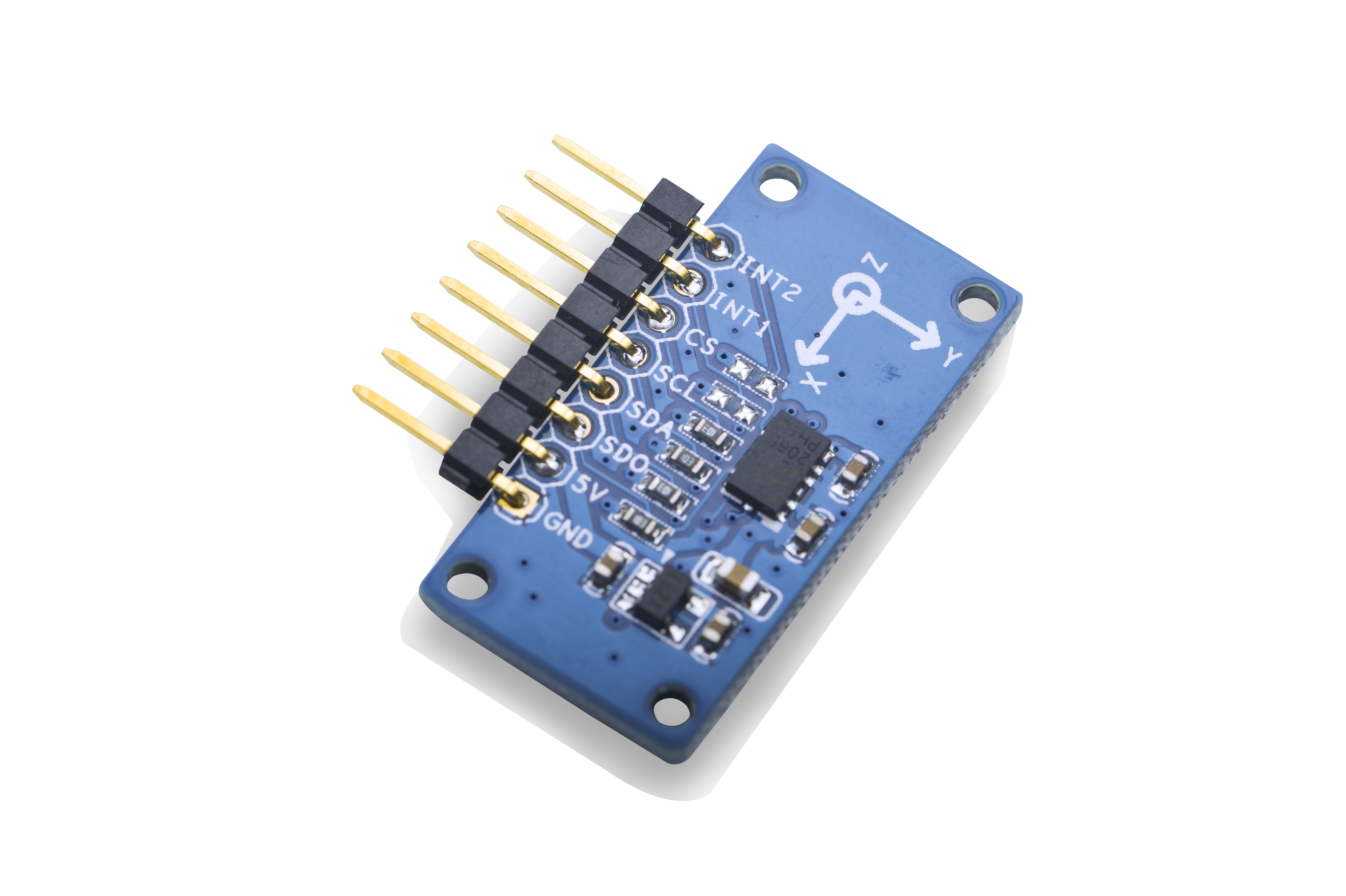
- This module measures the static acceleration of gravity in three axis x, y and z resulting from motion or shock.
- Its digital interface is IIC or SPI.
- It is integrated with an ADXL345 chip with high resolution (13-bit) measurement at ±2g, ±4g, ±8g and ±16g.
- The module is powered by 5V and converts 5V to 3.3V to ADXL345.
2 Features
- I2C, 3.3V
- 13-bit, up to +-16g
- 2.54mm spacing pin interface
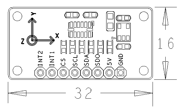
- PCB dimension(mm): 16 x 32
- Pin Description:
| Pin | Description |
| INT2 | Interrupt |
| INT1 | Interrupt |
| CS | Enable |
| SCL | I2C SCL |
| SDA | I2C SDA |
| SDO | Set Slave Address |
| 5V | Supply Voltage 5V |
| GND | Ground |
3 Basic Device Operation
- The ADXL345 is a small, thin, ultralow power, 3-axis accelerometer with high resolution (13-bit) measurement at up to ±16 g. Digital output data is formatted as 16-bit twos complement and is acces-sible through either a SPI (3- or 4-wire) or I2C digital interface.
- The ADXL345 is well suited for mobile device applications. It measures the static acceleration of gravity in tilt-sensing appli-cations, as well as dynamic acceleration resulting from motion or shock. Its high resolution (3.9 mg/LSB) enables measurement of inclination changes less than 1.0°.
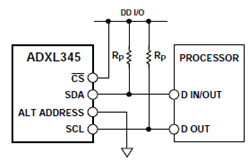
- The ADXL345 conforms to the UM1024 I2C Specification. It supports standard (100 kHz) and fast (400 kHz) data transfer modes. If the CS is tied high it will be in the I2C mode. If the CS or ALT ADDRESS pin is floating or unconnected the state will be unknown.
- The module's I2C connection diagram is as follows:
4 Applications
4.1 Connect to NanoPi M1
Refer to the following connection diagram to connect the module to the NanoPi M1:
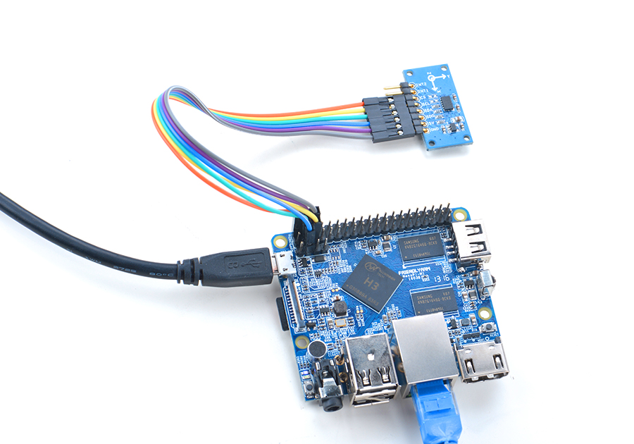
Connection Details:
| Matrix-3_Axis_Digital_Accelerometer | NanoPi M1 |
| INT2 | NC |
| INT1 | NC |
| CS | Pin2 |
| SCL | Pin5 |
| SDA | Pin3 |
| SDO | High, it is connected to the GPIO pin-header's 3.3V |
| 5V | Pin4 |
| GND | Pin6 |
4.2 Connect to NanoPi 2
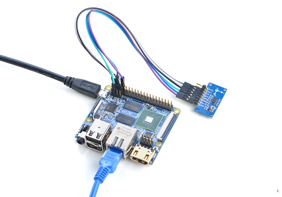
Refer to the following connection diagram to connect the module to the NanoPi 2:
Connection Details:
| Matrix-3_Axis_Digital_Accelerometer | NanoPi 2 |
| INT2 | NC |
| INT1 | NC |
| CS | Pin2 |
| SCL | Pin5 |
| SDA | Pin3 |
| SDO | High, it is connected to the GPIO pin-header's 3.3V |
| 5V | Pin4 |
| GND | Pin6 |
4.3 Connect to NanoPi M2 / NanoPi 2 Fire
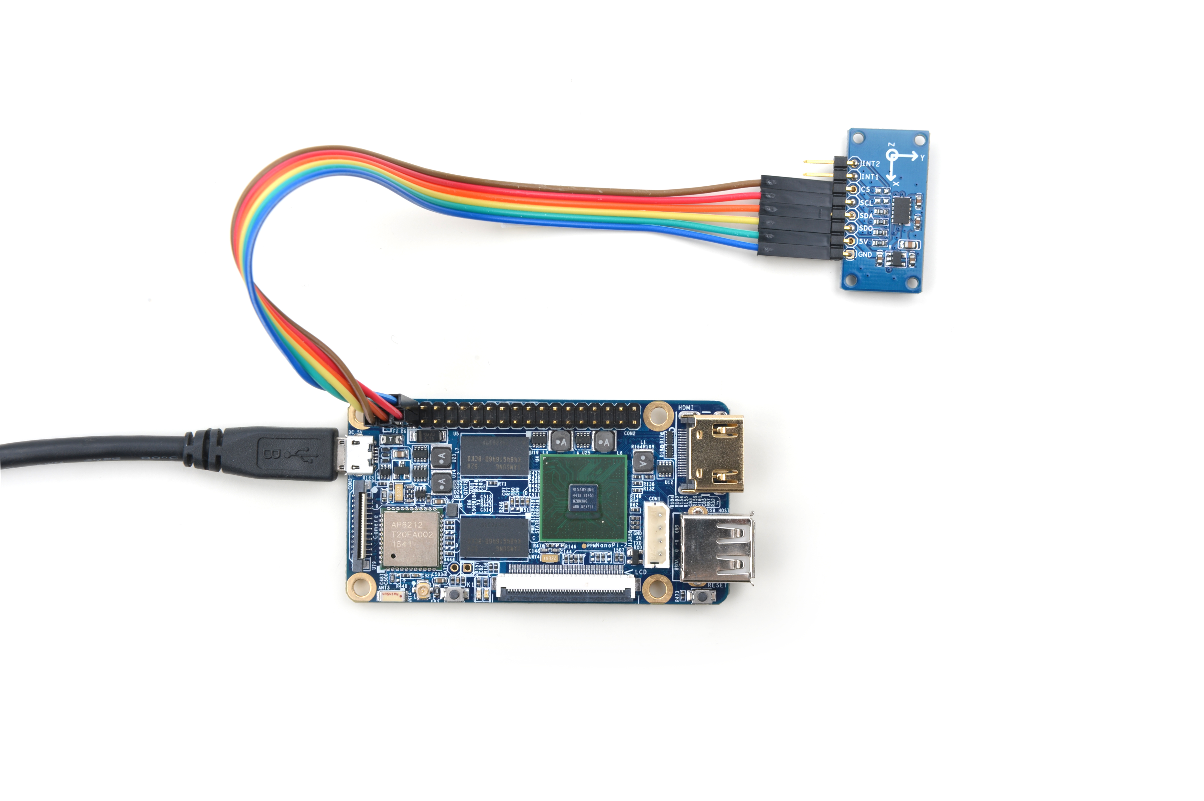
Refer to the following connection diagram to connect the module to the NanoPi M2/ NanoPi 2 Fire:
Connection Details:
| Matrix-3_Axis_Digital_Accelerometer | NanoPi M2 |
| INT2 | NC |
| INT1 | NC |
| CS | Pin2 |
| SCL | Pin5 |
| SDA | Pin3 |
| SDO | High, it is connected to the GPIO pin-header's 3.3V |
| 5V | Pin4 |
| GND | Pin6 |
4.4 Connect to NanoPC-T2
Refer to the following connection diagram to connect the module to the NanoPC-T2:
Matrix-3_Axis_Digital_Accelerometer_NanoPC-T2
Connection Details:
| Matrix-3_Axis_Digital_Accelerometer | NanoPC-T2 |
| INT2 | NC |
| INT1 | NC |
| CS | USB Host 5V |
| SCL | Pin5 |
| SDA | Pin6 |
| SDO | USB Host 5V |
| 5V | Pin29 |
| GND | Pin30 |
5 Compile & Run Test Program
Boot your ARM board with Debian and copy the matrix code:
$ apt-get update && apt-get install git
$ git clone https://github.com/friendlyarm/matrix.git
If your cloning is done successfully a "matrix" directory will be generated.
Compile and install Matrix:
$ cd matrix
$ make && make install
Run test program:
$ matrix-accelerometerNote: this module is not plug and play therefore before running the module please make sure it is connected to an ARM board.
Here is what you should observe:
The position is (-6, 3, 236)
6 Code Sample
This Matrix code sample can work with all the ARM boards mentioned in this module's wiki. The name of this code sample is "matrix-3_axis_digital_accelerometer". Here is its source code:
int main(int argc, char ** argv)
{
    char position[BUF_SIZE];
    int board;

    if ((board = boardInit()) < 0) {
        printf("Fail to init board\n");
        return -1;
    }

    system("modprobe adxl34x");
    system("modprobe adxl34x-i2c");
    memset(position, 0, BUF_SIZE);
    if (adxl34xRead(position) > 0) {
        printf("The position is %s", position);
    } else {
        printf("Fail to get position\n");
    }
    system("rmmod adxl34x-i2c");
    system("rmmod adxl34x");

    return 0;
}
For more details about this APIs called in this code sample refer to Matrix API reference manual
7 Resources
8 Update Log
8.1 Feb-23-2016
- Changed CS pin spec in Section 5.1
- Added driver's source code location in Section 5.2
8.2 June-17-2016
- Re-organized and simplified wiki
