Difference between revisions of "Matrix - Sound Sensor"
(→与NanoPi 2连接使用) |
(→Update Log) |
||
| (6 intermediate revisions by the same user not shown) | |||
| Line 29: | Line 29: | ||
* This sound sensor functions like a microphone which receives sound waves and convert them to images which show the sound waves' vibration. When it receives a sound wave it will output 1 but cannot measure its strength. | * This sound sensor functions like a microphone which receives sound waves and convert them to images which show the sound waves' vibration. When it receives a sound wave it will output 1 but cannot measure its strength. | ||
| + | |||
| + | ==Applications== | ||
| + | ===Connect to NanoPi M1=== | ||
| + | Refer to the following connection diagram to connect the module to the NanoPi M1:<br> | ||
| + | [[File:Matrix-Sound_Sensor_nanopi_m1.jpg|frameless|600px|Matrix-Sound_Sensor_nanopi_m1]] | ||
| + | |||
| + | Connection Details: | ||
| + | {| class="wikitable" | ||
| + | |- | ||
| + | |Matrix-Sound_Sensor || NanoPi M1 | ||
| + | |- | ||
| + | |S || Pin7 | ||
| + | |- | ||
| + | |V || Pin4 | ||
| + | |- | ||
| + | |G || Pin6 | ||
| + | |} | ||
| + | |||
| + | ===Connect to NanoPi 2=== | ||
| + | Refer to the following connection diagram to connect the module to the NanoPi 2:<br> | ||
| + | [[File:Matrix-Sound_Sensor_nanopi_2.jpg|frameless|600px|Matrix-Sound_Sensor_nanopi_2]] | ||
| + | |||
| + | Connection Details: | ||
| + | {| class="wikitable" | ||
| + | |- | ||
| + | |Matrix-Sound_Sensor || NanoPi 2 | ||
| + | |- | ||
| + | |S || Pin7 | ||
| + | |- | ||
| + | |V || Pin4 | ||
| + | |- | ||
| + | |G || Pin6 | ||
| + | |} | ||
| + | |||
| + | ===Connect to NanoPi M2 / NanoPi 2 Fire=== | ||
| + | Refer to the following connection diagram to connect the module to the NanoPi M2/ NanoPi 2 Fire:<br> | ||
| + | [[File:Matrix-Sound_Sensor_nanopi_m2.jpg|frameless|600px|Matrix-Sound_Sensor_nanopi_m2]] | ||
| + | |||
| + | Connection Details: | ||
| + | {| class="wikitable" | ||
| + | |- | ||
| + | |Matrix-Sound_Sensor || NanoPi M2 | ||
| + | |- | ||
| + | |S || Pin7 | ||
| + | |- | ||
| + | |V || Pin4 | ||
| + | |- | ||
| + | |G || Pin6 | ||
| + | |} | ||
| + | |||
| + | ===Connect to NanoPC-T2=== | ||
| + | Refer to the following connection diagram to connect the module to the NanoPC-T2:<br> | ||
| + | [[File:Matrix-Sound_Sensor_NanoPC-T2.jpg|frameless|600px|Matrix-Sound_Sensor_NanoPC-T2]] | ||
| + | |||
| + | Connection Details: | ||
| + | {| class="wikitable" | ||
| + | |- | ||
| + | |Matrix-Sound_Sensor || NanoPC-T2 | ||
| + | |- | ||
| + | |S || Pin15 | ||
| + | |- | ||
| + | |V || Pin29 | ||
| + | |- | ||
| + | |G || Pin30 | ||
| + | |} | ||
| + | |||
| + | ==Compile & Run Test Program== | ||
| + | Boot your ARM board with Debian and copy the matrix code: | ||
| + | <syntaxhighlight lang="bash"> | ||
| + | $ apt-get update && apt-get install git | ||
| + | $ git clone https://github.com/friendlyarm/matrix.git | ||
| + | </syntaxhighlight> | ||
| + | If your cloning is done successfully a "matrix" directory will be generated. | ||
| + | |||
| + | Compile and install Matrix: | ||
| + | <syntaxhighlight lang="bash"> | ||
| + | $ cd matrix | ||
| + | $ make && make install | ||
| + | </syntaxhighlight> | ||
| + | |||
| + | Run test program: | ||
| + | <syntaxhighlight lang="bash"> | ||
| + | $ matrix-gpio_int | ||
| + | </syntaxhighlight> | ||
| + | Note: this module is not plug and play therefore before running the module please make sure it is connected to an ARM board.<br> | ||
| + | Here is what you should observe:<br> | ||
| + | <syntaxhighlight lang="bash"> | ||
| + | Waiting event... | ||
| + | Device[0] value is 1 | ||
| + | </syntaxhighlight> | ||
| + | When there is a sound an event will be triggered and detected. | ||
| + | |||
| + | ==Code Sample== | ||
| + | This Matrix code sample can work with all the ARM boards mentioned in this module's wiki. The name of this code sample is "matrix-gpio_int". Here is its source code: | ||
| + | <syntaxhighlight lang="c"> | ||
| + | int main(int argc, char ** argv) | ||
| + | { | ||
| + | int i, board; | ||
| + | int retSize = -1; | ||
| + | char value[ARRAY_SIZE(dev)]; | ||
| + | |||
| + | if ((board = boardInit()) < 0) { | ||
| + | printf("Fail to init board\n"); | ||
| + | return -1; | ||
| + | } | ||
| + | |||
| + | if (argc == 2) | ||
| + | dev[0].pin = atoi(argv[1]); | ||
| + | system("modprobe "DRIVER_MODULE); | ||
| + | signal(SIGINT, intHandler); | ||
| + | if (board == BOARD_NANOPI_T2) | ||
| + | dev[0].pin = GPIO_PIN(15); | ||
| + | printf("Use GPIO_PIN(%d)\n", dev[0].pin); | ||
| + | if ((devFD =sensorInit(dev, ARRAY_SIZE(dev))) == -1) { | ||
| + | printf("Fail to init sensor\n"); | ||
| + | goto err; | ||
| + | } | ||
| + | printf("Waiting event...\n"); | ||
| + | if ((retSize = sensorRead(devFD, value, ARRAY_SIZE(dev))) == -1) { | ||
| + | printf("Fail to read sensors\n"); | ||
| + | } | ||
| + | if (retSize > 0) { | ||
| + | i = 0; | ||
| + | for (i=0; i<retSize; i++) { | ||
| + | printf("Device[%d] value is %d\n", i, value[i]); | ||
| + | } | ||
| + | } | ||
| + | sensorDeinit(devFD); | ||
| + | err: | ||
| + | system("rmmod "DRIVER_MODULE); | ||
| + | return 0; | ||
| + | } | ||
| + | </syntaxhighlight> | ||
| + | For more details about this APIs called in this code sample refer to [[Matrix API reference manual]] <br> | ||
| + | |||
| + | <!--- | ||
==Download Matrix Source Code== | ==Download Matrix Source Code== | ||
All the matrix modules' code samples are open source. They are maintained on GitHub - https://github.com/friendlyarm/matrix.git <br> | All the matrix modules' code samples are open source. They are maintained on GitHub - https://github.com/friendlyarm/matrix.git <br> | ||
| Line 83: | Line 219: | ||
The modules are under the "modules" directory. The driver's source code is in github: https://github.com/friendlyarm/linux-3.4.y.git <br> | The modules are under the "modules" directory. The driver's source code is in github: https://github.com/friendlyarm/linux-3.4.y.git <br> | ||
| − | === | + | ===Run Test Program=== |
| − | + | Please insert a TF card which is flashed with Debian to a Linux host and mount its boot and rootfs sections.<br> | |
| − | + | We assume the rootfs is mounted to /media/rootfs then please run the following commands to copy the module, library and test program to the card.<br> | |
<syntaxhighlight lang="bash"> | <syntaxhighlight lang="bash"> | ||
$ cp modules /media/rootfs/ -r | $ cp modules /media/rootfs/ -r | ||
| Line 92: | Line 228: | ||
</syntaxhighlight> | </syntaxhighlight> | ||
| − | + | Insert this TF card to your NanoPi 2, power on and run the following commands to load the driver.<br> | |
<syntaxhighlight lang="bash"> | <syntaxhighlight lang="bash"> | ||
$ cd /modules | $ cd /modules | ||
| Line 98: | Line 234: | ||
</syntaxhighlight> | </syntaxhighlight> | ||
| − | + | Start the matrix-sound_sensor program.<br> | |
<syntaxhighlight lang="bash"> | <syntaxhighlight lang="bash"> | ||
$ matrix-sound_sensor | $ matrix-sound_sensor | ||
</syntaxhighlight> | </syntaxhighlight> | ||
| − | + | Here is what you expect to observe:<br> | |
[[File:matrix-sound_sensor_result.png|frameless|600px|matrix-sound_sensor_result]] <br> | [[File:matrix-sound_sensor_result.png|frameless|600px|matrix-sound_sensor_result]] <br> | ||
| − | + | When you talk to the module your speech will be detected. When you adjust the resistor the module's sensitivity will be changed | |
| − | === | + | ===Code Sample=== |
<syntaxhighlight lang="c"> | <syntaxhighlight lang="c"> | ||
static struct sensor sound[] = { | static struct sensor sound[] = { | ||
| Line 328: | Line 464: | ||
==Connect to Arduino== | ==Connect to Arduino== | ||
| + | ---> | ||
==Resources== | ==Resources== | ||
| Line 335: | Line 472: | ||
* Added the description for "NanoPi 2 branch" in Section 4 | * Added the description for "NanoPi 2 branch" in Section 4 | ||
* Added Section 5: Connect to NanoPi 2 | * Added Section 5: Connect to NanoPi 2 | ||
| − | + | ===June-24-2016=== | |
| + | * Re-organized and simplified wiki | ||
<!-- | <!-- | ||
Latest revision as of 15:11, 24 June 2016
Contents
1 Introduction
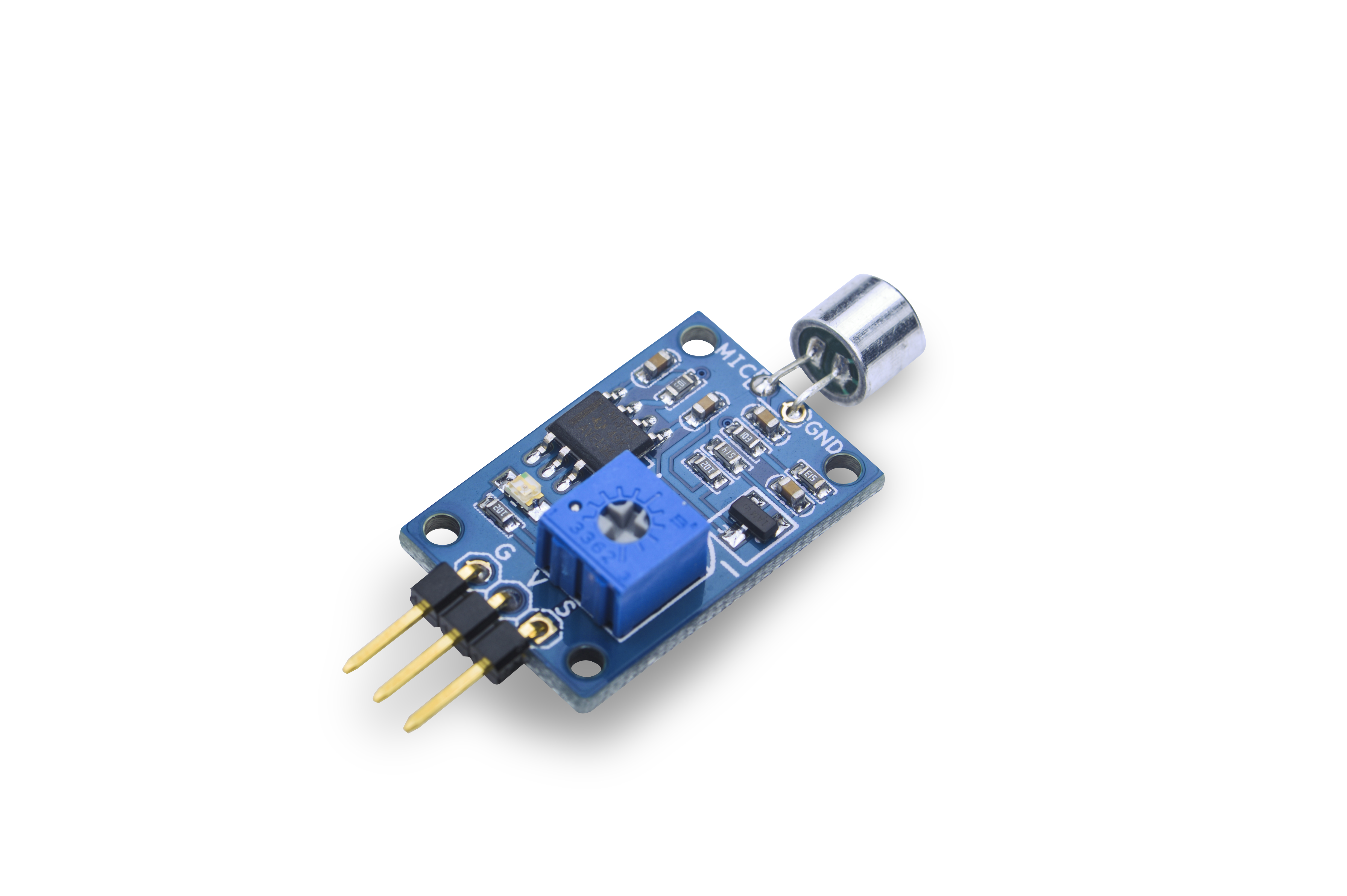
- The Matrix-Sound_Sensor module is used to detect sound.
- The module has a variable resistor which can be used to control the threshold value of a sound level. Only when a sound level's value is greater than this threshold the module can detect it. Turning clockwise increases this threshold value. Turning anticlockwise decreases this value.
- By default this module's output level is high. When it detects sound signals its output level will turn low. When sound signals are not detected its output will turn high again without time delay.
2 Features
- Variable threshold value
- 2.54mm spacing pin interface
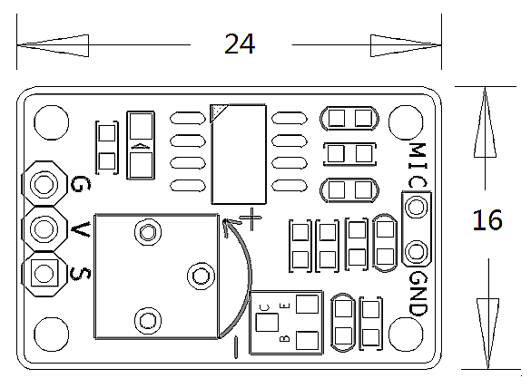
- PCB dimension (mm): 16 x 24
- Pin Description:
| Pin | Description |
| S | GPIO |
| V | Supply Voltage 5V |
| G | Ground |
3 Basic Device Operation
- The module contains an electret condenser microphone. Sound waves impinging on the diaphragm cause the capacitance between it and the back plate to change synchronously, this in turn induces an AC voltage on the back plate.
- This sound sensor functions like a microphone which receives sound waves and convert them to images which show the sound waves' vibration. When it receives a sound wave it will output 1 but cannot measure its strength.
4 Applications
4.1 Connect to NanoPi M1
Refer to the following connection diagram to connect the module to the NanoPi M1:
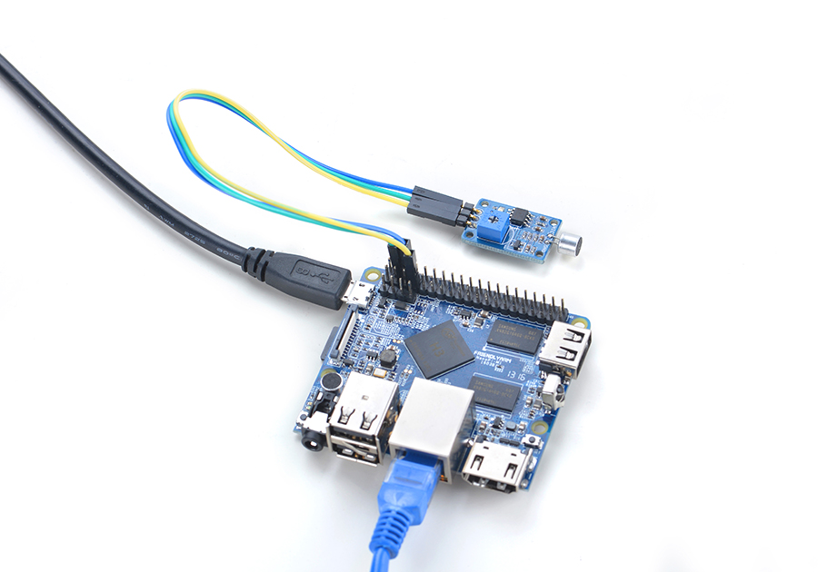
Connection Details:
| Matrix-Sound_Sensor | NanoPi M1 |
| S | Pin7 |
| V | Pin4 |
| G | Pin6 |
4.2 Connect to NanoPi 2
Refer to the following connection diagram to connect the module to the NanoPi 2:
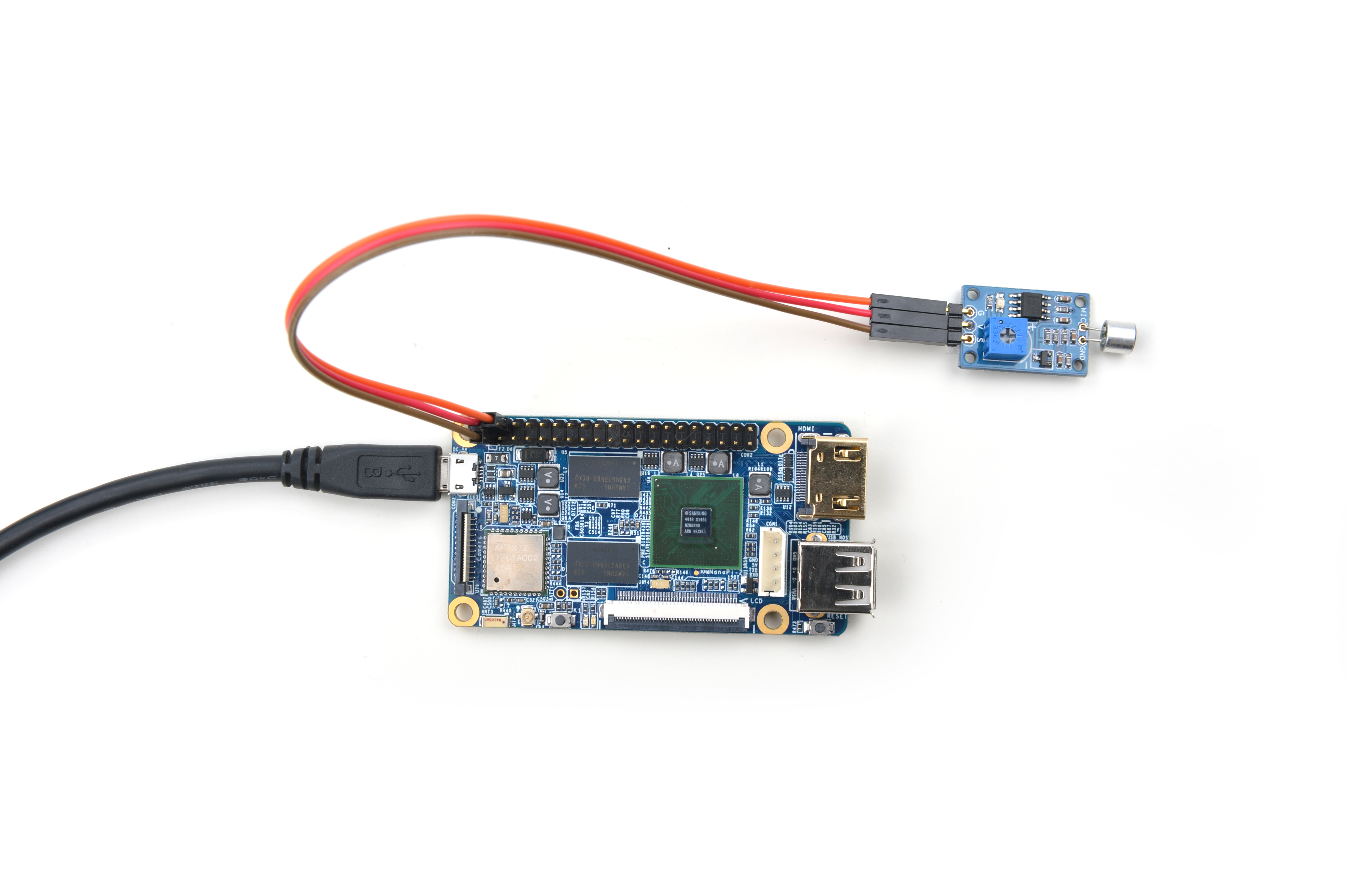
Connection Details:
| Matrix-Sound_Sensor | NanoPi 2 |
| S | Pin7 |
| V | Pin4 |
| G | Pin6 |
4.3 Connect to NanoPi M2 / NanoPi 2 Fire
Refer to the following connection diagram to connect the module to the NanoPi M2/ NanoPi 2 Fire:
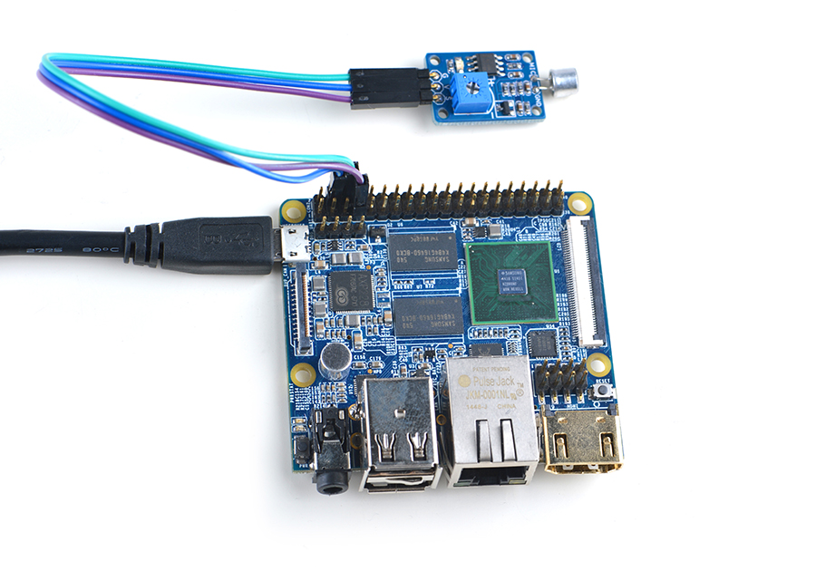
Connection Details:
| Matrix-Sound_Sensor | NanoPi M2 |
| S | Pin7 |
| V | Pin4 |
| G | Pin6 |
4.4 Connect to NanoPC-T2
Refer to the following connection diagram to connect the module to the NanoPC-T2:
Matrix-Sound_Sensor_NanoPC-T2
Connection Details:
| Matrix-Sound_Sensor | NanoPC-T2 |
| S | Pin15 |
| V | Pin29 |
| G | Pin30 |
5 Compile & Run Test Program
Boot your ARM board with Debian and copy the matrix code:
$ apt-get update && apt-get install git
$ git clone https://github.com/friendlyarm/matrix.git
If your cloning is done successfully a "matrix" directory will be generated.
Compile and install Matrix:
$ cd matrix
$ make && make install
Run test program:
$ matrix-gpio_intNote: this module is not plug and play therefore before running the module please make sure it is connected to an ARM board.
Here is what you should observe:
Waiting event...
Device[0] value is 1
When there is a sound an event will be triggered and detected.
6 Code Sample
This Matrix code sample can work with all the ARM boards mentioned in this module's wiki. The name of this code sample is "matrix-gpio_int". Here is its source code:
int main(int argc, char ** argv)
{
    int i, board;
    int retSize = -1;
    char value[ARRAY_SIZE(dev)];

    if ((board = boardInit()) < 0) {
        printf("Fail to init board\n");
        return -1;
    }

    if (argc == 2)
        dev[0].pin = atoi(argv[1]);
    system("modprobe "DRIVER_MODULE);
    signal(SIGINT, intHandler);
    if (board == BOARD_NANOPI_T2)
        dev[0].pin = GPIO_PIN(15);
    printf("Use GPIO_PIN(%d)\n", dev[0].pin);
    if ((devFD =sensorInit(dev, ARRAY_SIZE(dev))) == -1) {
        printf("Fail to init sensor\n");
        goto err;
    }
    printf("Waiting event...\n");
    if ((retSize = sensorRead(devFD, value, ARRAY_SIZE(dev))) == -1) {
        printf("Fail to read sensors\n");
    }
    if (retSize > 0) {
        i = 0;
        for (i=0; i<retSize; i++) {
            printf("Device[%d] value is %d\n", i, value[i]);
        }
    }
    sensorDeinit(devFD);
err:
    system("rmmod "DRIVER_MODULE);
    return 0;
}
For more details about this APIs called in this code sample refer to Matrix API reference manual
7 Resources
8 Update Log
8.1 Feb-23-2016
- Added the description for "NanoPi 2 branch" in Section 4
- Added Section 5: Connect to NanoPi 2
8.2 June-24-2016
- Re-organized and simplified wiki
