Difference between revisions of "Matrix - Buzzer"
(→运行测试程序) |
(→Applications) |
||
| (5 intermediate revisions by the same user not shown) | |||
| Line 9: | Line 9: | ||
* 3 PIN interface | * 3 PIN interface | ||
* PCB dimension (mm): 16 x 24 | * PCB dimension (mm): 16 x 24 | ||
| − | [[File:buzzerpcb.png|frameless|400px| | + | [[File:buzzerpcb.png|frameless|400px|Buzzer PCB]] |
* Pin Description: | * Pin Description: | ||
| Line 26: | Line 26: | ||
A passive buzzer will not tweet if DC signals are used; instead, you need to use square waves whose frequency is between 2K and 5K to drive it. If you use GPIO signals to drive it you need to pull the GPIO high first and then low to generate oscillation. The oscillation frequency is generated by the time in which GPIO signals turn from high to low. The buzzer will generate different sounds based on different frequencies. | A passive buzzer will not tweet if DC signals are used; instead, you need to use square waves whose frequency is between 2K and 5K to drive it. If you use GPIO signals to drive it you need to pull the GPIO high first and then low to generate oscillation. The oscillation frequency is generated by the time in which GPIO signals turn from high to low. The buzzer will generate different sounds based on different frequencies. | ||
| + | ==Applications== | ||
| + | ===Connect to NanoPi 2=== | ||
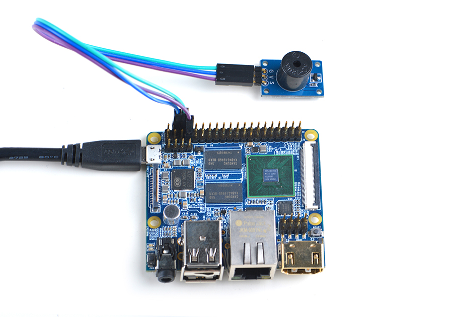
| + | Refer to the following connection diagram to connect the module to the NanoPi M1<br> | ||
| + | [[File:Matrix-Buzzer_nanopi_2.jpg|frameless|600px|Matrix-Buzzer_nanopi_2]] | ||
| + | |||
| + | Connection Details: | ||
| + | {| class="wikitable" | ||
| + | |- | ||
| + | |Matrix-Buzzer || NanoPi 2 | ||
| + | |- | ||
| + | |G || Pin6 | ||
| + | |- | ||
| + | |V || Pin4 | ||
| + | |- | ||
| + | |S || Pin22 | ||
| + | |} | ||
| + | |||
| + | ===Connect to NanoPi M2 / NanoPi 2 Fire=== | ||
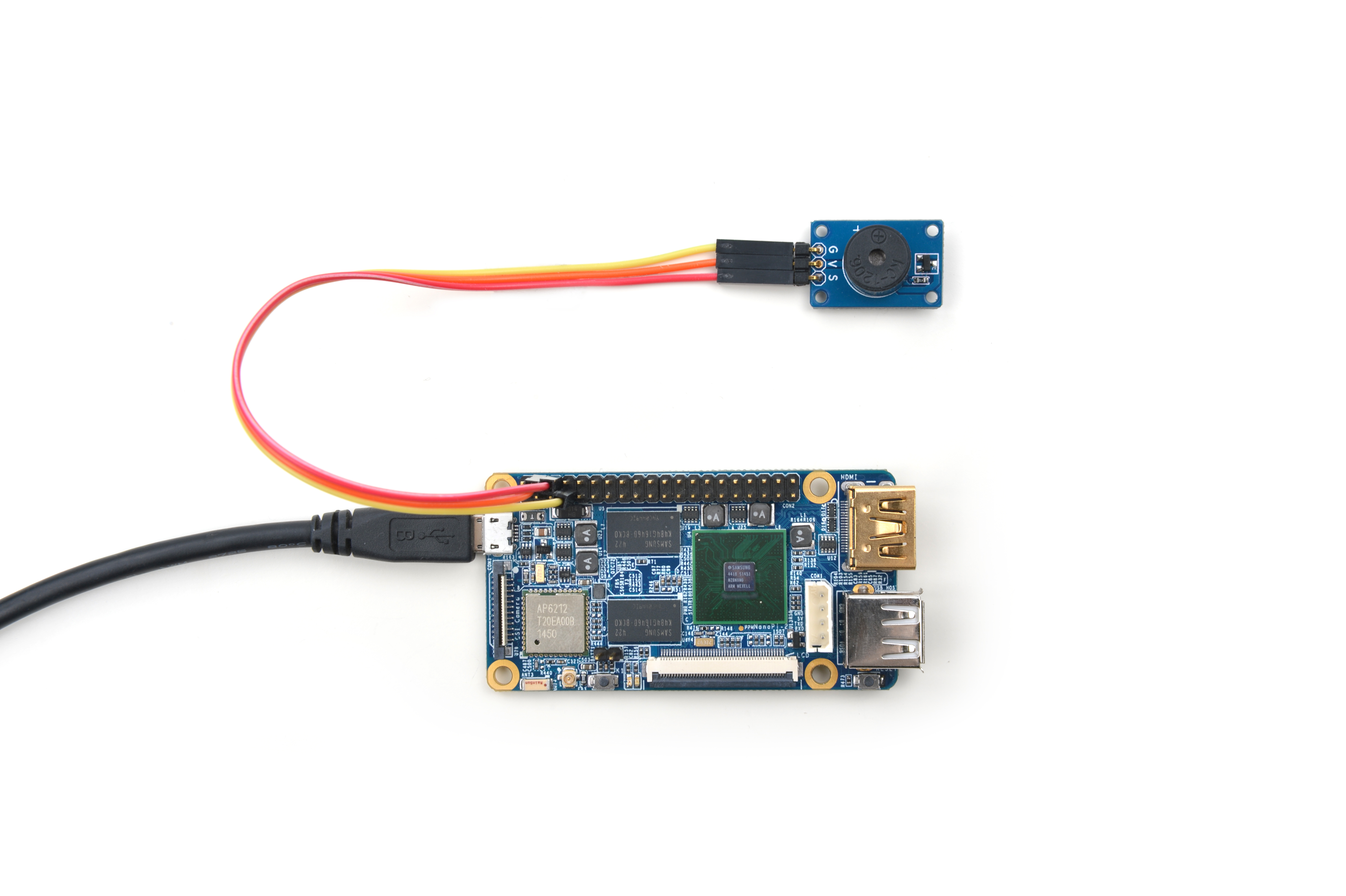
| + | Refer to the following connection diagram to connect the module to the NanoPi M2/ NanoPi 2 Fire:<br> | ||
| + | [[File:Matrix-Buzzer_nanopi_m2.jpg|frameless|600px|Matrix-Buzzer_nanopi_m2]] | ||
| + | |||
| + | Connection Details: | ||
| + | {| class="wikitable" | ||
| + | |- | ||
| + | |Matrix-Buzzer || NanoPi M2 | ||
| + | |- | ||
| + | |G || Pin6 | ||
| + | |- | ||
| + | |V || Pin4 | ||
| + | |- | ||
| + | |S || Pin12 | ||
| + | |} | ||
| + | |||
| + | ===Connect to NanoPC-T2=== | ||
| + | Refer to the following connection diagram to connect the module to the NanoPC-T2:<br> | ||
| + | [[File:Matrix-Buzzer_nanopc_t2.jpg|frameless|600px|Matrix-Buzzer_nanopc_t2]] | ||
| + | |||
| + | Connection Details: | ||
| + | {| class="wikitable" | ||
| + | |- | ||
| + | |Matrix-Buzzer || NanoPC-T2 | ||
| + | |- | ||
| + | |S || Pin23 | ||
| + | |- | ||
| + | |V || Pin29 | ||
| + | |- | ||
| + | |G || Pin30 | ||
| + | |} | ||
| + | |||
| + | ==Compile & Run Test Program== | ||
| + | Boot your ARM board with Debian and copy the matrix code: | ||
| + | <syntaxhighlight lang="bash"> | ||
| + | $ apt-get update && apt-get install git | ||
| + | $ git clone https://github.com/friendlyarm/matrix.git | ||
| + | </syntaxhighlight> | ||
| + | If your cloning is done successfully a "matrix" directory will be generated. | ||
| + | |||
| + | Compile and install Matrix: | ||
| + | <syntaxhighlight lang="bash"> | ||
| + | $ cd matrix | ||
| + | $ make && make install | ||
| + | </syntaxhighlight> | ||
| + | |||
| + | Run test program: | ||
| + | <syntaxhighlight lang="bash"> | ||
| + | $ matrix-pwm | ||
| + | </syntaxhighlight> | ||
| + | Note: this module is not plug and play therefore before running the module please make sure it is connected to an ARM board.<br> | ||
| + | Here is what you should observe:<br> | ||
| + | <syntaxhighlight lang="bash"> | ||
| + | Using default config: channel=0 freq=1000Hz duty=500 | ||
| + | Press enter to stop PWM | ||
| + | </syntaxhighlight> | ||
| + | You can hear the buzzer beeping. The range of the duty cycle is 0 ~ 1000. When you hit "enter" the buzzer will be stopped. | ||
| + | |||
| + | ==Code Sample== | ||
| + | This Matrix code sample can work with all the ARM boards mentioned in this module's wiki. The name of this code sample is "matrix-pwm". Here is its source code: | ||
| + | <syntaxhighlight lang="c"> | ||
| + | int main(int argc, char ** argv) | ||
| + | { | ||
| + | int Hz, duty, board; | ||
| + | |||
| + | if ((board = boardInit()) < 0) { | ||
| + | printf("Fail to init board\n"); | ||
| + | return -1; | ||
| + | } | ||
| + | |||
| + | system("modprobe "DRIVER_MODULE); | ||
| + | signal(SIGINT, intHandler); | ||
| + | if (argc == 4) { | ||
| + | // Usage:matrix-pwm channel freq duty[0~1000] | ||
| + | pwm = atoi(argv[1]); | ||
| + | Hz = atoi(argv[2]); | ||
| + | duty = atoi(argv[3]); | ||
| + | } else { | ||
| + | Hz = 1000; | ||
| + | duty = 500; | ||
| + | printf("Using default config: channel=%d freq=%dHz duty=%d\n", pwm, Hz, duty); | ||
| + | } | ||
| + | if (PWMPlay(pwm, Hz, duty) == -1) { | ||
| + | printf("Fail to output PWM\n"); | ||
| + | } | ||
| + | printf("Press enter to stop PWM\n"); | ||
| + | getchar(); | ||
| + | PWMStop(pwm); | ||
| + | system("rmmod "DRIVER_MODULE); | ||
| + | |||
| + | return 0; | ||
| + | } | ||
| + | </syntaxhighlight> | ||
| + | For more details about this APIs called in this code sample refer to [[Matrix API reference manual]] <br> | ||
| + | <!--- | ||
==Download Matrix Source Code== | ==Download Matrix Source Code== | ||
All the matrix modules' code samples are open source. They are maintained on GitHub - https://github.com/friendlyarm/matrix.git <br> | All the matrix modules' code samples are open source. They are maintained on GitHub - https://github.com/friendlyarm/matrix.git <br> | ||
| Line 102: | Line 214: | ||
Here is what you expect to observe:<br> | Here is what you expect to observe:<br> | ||
[[File:matrix-buzzer_result.png|frameless|600px|matrix-buzzer_result]] <br> | [[File:matrix-buzzer_result.png|frameless|600px|matrix-buzzer_result]] <br> | ||
| − | You can hear the buzzer beeping | + | You can hear the buzzer beeping. The default PWM frequency is 1KHz and the duty cycle is 50%. |
===Code Sample=== | ===Code Sample=== | ||
| Line 306: | Line 418: | ||
==Connect to Arduino== | ==Connect to Arduino== | ||
| + | ---> | ||
==Resources== | ==Resources== | ||
| Line 313: | Line 426: | ||
* Added the description for "NanoPi 2 branch" in Section 4 | * Added the description for "NanoPi 2 branch" in Section 4 | ||
* Added Section 5: Connect to NanoPi 2 | * Added Section 5: Connect to NanoPi 2 | ||
| − | + | ===June-17-2016=== | |
| + | * Re-organized and simplified wiki | ||
<!-- | <!-- | ||
Latest revision as of 10:32, 19 June 2016
Contents
1 Introduction
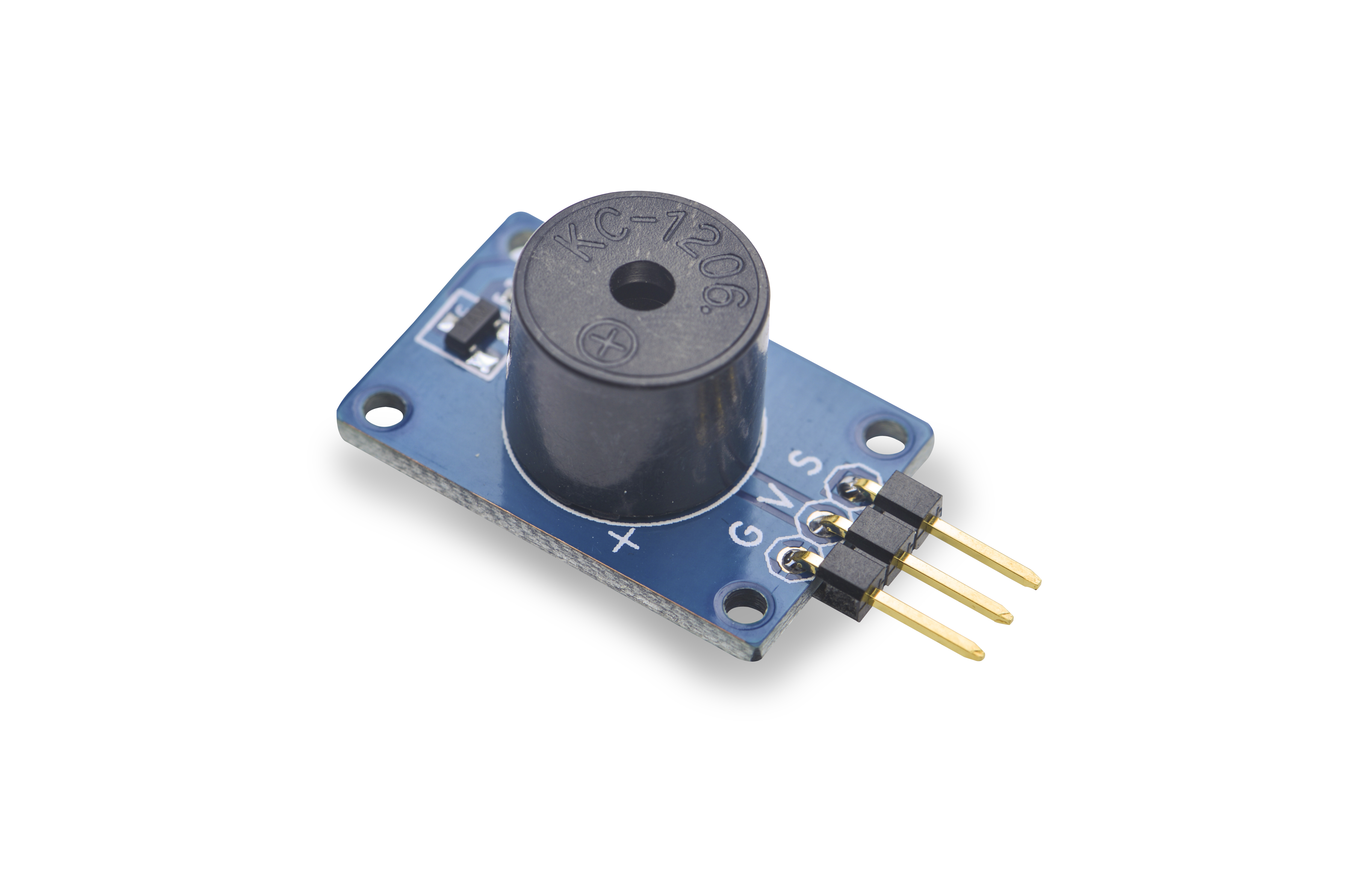
- The Matrix-Buzzer is a passive buzzer. To drive this buzzer an oscillating source generating 2K - 5K square waves is needed.
- It can be used in electronic devices that need sound generators.
2 Features
- 3 PIN interface
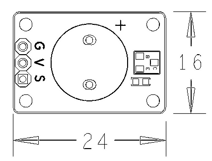
- PCB dimension (mm): 16 x 24
- Pin Description:
| Pin | Description |
| V | Supply Voltage 5V |
| G | Ground |
| S | PWM Input |
3 Basic Device Operation
A passive buzzer will not tweet if DC signals are used; instead, you need to use square waves whose frequency is between 2K and 5K to drive it. If you use GPIO signals to drive it you need to pull the GPIO high first and then low to generate oscillation. The oscillation frequency is generated by the time in which GPIO signals turn from high to low. The buzzer will generate different sounds based on different frequencies.
4 Applications
4.1 Connect to NanoPi 2
Refer to the following connection diagram to connect the module to the NanoPi M1

Connection Details:
| Matrix-Buzzer | NanoPi 2 |
| G | Pin6 |
| V | Pin4 |
| S | Pin22 |
4.2 Connect to NanoPi M2 / NanoPi 2 Fire
Refer to the following connection diagram to connect the module to the NanoPi M2/ NanoPi 2 Fire:

Connection Details:
| Matrix-Buzzer | NanoPi M2 |
| G | Pin6 |
| V | Pin4 |
| S | Pin12 |
4.3 Connect to NanoPC-T2
Refer to the following connection diagram to connect the module to the NanoPC-T2:
Matrix-Buzzer_nanopc_t2
Connection Details:
| Matrix-Buzzer | NanoPC-T2 |
| S | Pin23 |
| V | Pin29 |
| G | Pin30 |
5 Compile & Run Test Program
Boot your ARM board with Debian and copy the matrix code:
$ apt-get update && apt-get install git
$ git clone https://github.com/friendlyarm/matrix.git
If your cloning is done successfully a "matrix" directory will be generated.
Compile and install Matrix:
$ cd matrix
$ make && make install
Run test program:
$ matrix-pwmNote: this module is not plug and play therefore before running the module please make sure it is connected to an ARM board.
Here is what you should observe:
Using default config: channel=0 freq=1000Hz duty=500
Press enter to stop PWM
You can hear the buzzer beeping. The range of the duty cycle is 0 ~ 1000. When you hit "enter" the buzzer will be stopped.
6 Code Sample
This Matrix code sample can work with all the ARM boards mentioned in this module's wiki. The name of this code sample is "matrix-pwm". Here is its source code:
int main(int argc, char ** argv)
{
    int Hz, duty, board;

    if ((board = boardInit()) < 0) {
        printf("Fail to init board\n");
        return -1;
    }

    system("modprobe "DRIVER_MODULE);
    signal(SIGINT, intHandler);
    if (argc == 4) {
        // Usage:matrix-pwm channel freq duty[0~1000]
        pwm = atoi(argv[1]);
        Hz = atoi(argv[2]);
        duty = atoi(argv[3]);
    } else {
        Hz = 1000;
        duty = 500;
        printf("Using default config: channel=%d freq=%dHz duty=%d\n", pwm, Hz, duty);
    }
    if (PWMPlay(pwm, Hz, duty) == -1) {
        printf("Fail to output PWM\n");
    }
    printf("Press enter to stop PWM\n");
    getchar();
    PWMStop(pwm);
    system("rmmod "DRIVER_MODULE);

    return 0;
}
For more details about this APIs called in this code sample refer to Matrix API reference manual
7 Resources
8 Update Log
8.1 Feb-23-2016
- Added the description for "NanoPi 2 branch" in Section 4
- Added Section 5: Connect to NanoPi 2
8.2 June-17-2016
- Re-organized and simplified wiki

