Difference between revisions of "Matrix - RGB LED"
(→介绍) |
(→Resources) |
||
| (22 intermediate revisions by 2 users not shown) | |||
| Line 1: | Line 1: | ||
| − | [[Matrix - | + | [[Matrix - RGB LED/zh|查看中文]] |
| − | == | + | ==Introduction== |
[[File:Matrix-RGB_LED.png|thumb|]] | [[File:Matrix-RGB_LED.png|thumb|]] | ||
| − | *Matrix- | + | * The Matrix-RGB_LED is a RGB LED module. It has a 2.54mm pitch pin-header in which 5V is power supply, GND is ground, and R,G,B are connected to the LED’s red, green and blue pins. |
| + | * The inputs to Pin R, G and B can be either GPIO signals or PWM signals. The signal level can be either 3.3V or 5V. When the inputs to Pin R,G and B are high the LED will be the brightest.When the inputs to Pin R,G and B are low the LED will be completely off. When the inputs are PWM signals the LED's brightness can be controlled by controlling the PWM's duty cycle. | ||
| − | + | ==Features== | |
| + | * GPIO or PWM input, 3.3/5V, LED lightness controllable via PWM | ||
| + | * Small | ||
| + | * 2.54 mm pitch pin-header | ||
| + | * PCB dimension(mm): 16 x 24 | ||
| + | [[File:Matrix-RGB_LED_PCB.png|frameless|400px|]] | ||
| − | = | + | * Pin Description: |
| − | + | {| class="wikitable" | |
| + | |- | ||
| + | |Pin || Description | ||
| + | |- | ||
| + | |GND || Ground | ||
| + | |- | ||
| + | |5V || Supply Voltage 5V | ||
| + | |- | ||
| + | |R || Red | ||
| + | |- | ||
| + | |G || Green | ||
| + | |- | ||
| + | |B || Blue | ||
| + | |} | ||
| − | + | ==Basic Device Operation== | |
| − | + | * In the RGB_LED module three one-color LEDs(one red,one green and one blue) are housed in a single package.These three LEDs share one common anode or cathode.When applying control signals to the other three leads their corresponding LEDs will be on. When two or three LEDs are on simultaneously a different color will be produced.You can produce different colors by adjusting PWM signals' duty cycle. | |
| − | + | ==Applications== | |
| + | ===Connect to NanoPi M1=== | ||
| + | Refer to the following connection diagram to connect the module to the NanoPi M1:<br> | ||
| + | [[File:Matrix-RGBLED_nanopi_m1.jpg|frameless|600px|Matrix-RGBLED_nanopi_m1]] | ||
| + | |||
| + | Connection Details: | ||
{| class="wikitable" | {| class="wikitable" | ||
|- | |- | ||
| − | | | + | |Matrix-RGBLED || NanoPi M1 |
|- | |- | ||
| − | | | + | |R || Pin7 |
| + | |- | ||
| + | |G || Pin8 | ||
| + | |- | ||
| + | |B || Pin10 | ||
|- | |- | ||
| − | | | + | |V || Pin4 |
|- | |- | ||
| − | | | + | |G || Pin6 |
| + | |} | ||
| + | |||
| + | ===Connect to NanoPi 2=== | ||
| + | Refer to the following connection diagram to connect the module to the NanoPi 2:<br> | ||
| + | [[File:Matrix-RGB_LED_nanopi2.jpg|frameless|600px|Matrix-RGB_LED_nanopi2]] | ||
| + | |||
| + | Connection Details: | ||
| + | {| class="wikitable" | ||
|- | |- | ||
| − | | | + | |Matrix-RGBLED || NanoPi 2 |
| + | |- | ||
| + | |R || Pin7 | ||
| + | |- | ||
| + | |G || Pin8 | ||
| + | |- | ||
| + | |B || Pin10 | ||
| + | |- | ||
| + | |V || Pin4 | ||
| + | |- | ||
| + | |G || Pin6 | ||
|} | |} | ||
| − | == | + | ===Connect to NanoPi M2 / NanoPi 2 Fire=== |
| − | * | + | Refer to the following connection diagram to connect the module to the NanoPi M2/ NanoPi 2 Fire.<br> |
| + | [[File:Matrix-RGBLED_nanopi_m2.jpg|frameless|600px|Matrix-RGBLED_nanopi_m2]] | ||
| + | |||
| + | Connection Details: | ||
| + | {| class="wikitable" | ||
| + | |- | ||
| + | |Matrix-RGBLED || NanoPi M2 | ||
| + | |- | ||
| + | |R || Pin7 | ||
| + | |- | ||
| + | |G || Pin8 | ||
| + | |- | ||
| + | |B || Pin10 | ||
| + | |- | ||
| + | |V || Pin4 | ||
| + | |- | ||
| + | |G || Pin6 | ||
| + | |} | ||
| + | |||
| + | ===Connect to NanoPC-T2=== | ||
| + | Refer to the following connection diagram to connect the module to the NanoPC-T2:<br> | ||
| + | [[File:Matrix-RGBLED_NanoPC-T2.jpg|frameless|600px|Matrix-RGBLED_NanoPC-T2]] | ||
| + | |||
| + | Connection Details: | ||
| + | {| class="wikitable" | ||
| + | |- | ||
| + | |Matrix-RGBLED || NanoPC-T2 | ||
| + | |- | ||
| + | |R || Pin15 | ||
| + | |- | ||
| + | |G || Pin16 | ||
| + | |- | ||
| + | |B || Pin17 | ||
| + | |- | ||
| + | |V || Pin29 | ||
| + | |- | ||
| + | |G || Pin30 | ||
| + | |} | ||
| + | |||
| + | ==Compile & Run Test Program== | ||
| + | Boot your ARM board with Debian and copy the matrix code: | ||
| + | <syntaxhighlight lang="bash"> | ||
| + | $ apt-get update && apt-get install git | ||
| + | $ git clone https://github.com/friendlyarm/matrix.git | ||
| + | </syntaxhighlight> | ||
| + | If your cloning is done successfully a "matrix" directory will be generated. | ||
| + | |||
| + | Compile and install Matrix: | ||
| + | <syntaxhighlight lang="bash"> | ||
| + | $ cd matrix | ||
| + | $ make && make install | ||
| + | </syntaxhighlight> | ||
| + | |||
| + | Run test program: | ||
| + | <syntaxhighlight lang="bash"> | ||
| + | $ matrix-rgb_led | ||
| + | </syntaxhighlight> | ||
| + | Note: this module is not plug and play therefore before running the module please make sure it is connected to an ARM board.<br> | ||
| + | Here is what you should observe:<br> | ||
| + | <syntaxhighlight lang="bash"> | ||
| + | Set RGB LED: 0 | ||
| + | Set RGB LED: 1 | ||
| + | Set RGB LED: 2 | ||
| + | Set RGB LED: 3 | ||
| + | Set RGB LED: 4 | ||
| + | Set RGB LED: 5 | ||
| + | Set RGB LED: 6 | ||
| + | Set RGB LED: 7 | ||
| + | </syntaxhighlight> | ||
| + | You will see the LED displaying different colors. | ||
| + | |||
| + | ==Code Sample== | ||
| + | This Matrix code sample can work with all the ARM boards mentioned in this module's wiki. The name of this code sample is "matrix-rgb_led". Here is its source code: | ||
| + | <syntaxhighlight lang="c"> | ||
| + | int main(int argc, char ** argv) | ||
| + | { | ||
| + | int ret = -1; | ||
| + | int val, board; | ||
| + | |||
| + | if ((board = boardInit()) < 0) { | ||
| + | printf("Fail to init board\n"); | ||
| + | return -1; | ||
| + | } | ||
| + | if (board == BOARD_NANOPI_T2) { | ||
| + | ledPin1 = GPIO_PIN(15); | ||
| + | ledPin2 = GPIO_PIN(16); | ||
| + | ledPin3 = GPIO_PIN(17); | ||
| + | } | ||
| + | if ((ret = exportGPIOPin(ledPin1)) == -1) { | ||
| + | printf("exportGPIOPin(%d) failed\n", ledPin1); | ||
| + | } | ||
| + | if ((ret = setGPIODirection(ledPin1, GPIO_OUT)) == -1) { | ||
| + | printf("setGPIODirection(%d) failed\n", ledPin1); | ||
| + | } | ||
| + | if ((ret = exportGPIOPin(ledPin2)) == -1) { | ||
| + | printf("exportGPIOPin(%d) failed\n", ledPin2); | ||
| + | } | ||
| + | if ((ret = setGPIODirection(ledPin2, GPIO_OUT)) == -1) { | ||
| + | printf("setGPIODirection(%d) failed\n", ledPin2); | ||
| + | } | ||
| + | if ((ret = exportGPIOPin(ledPin3)) == -1) { | ||
| + | printf("exportGPIOPin(%d) failed\n", ledPin3); | ||
| + | } | ||
| + | if ((ret = setGPIODirection(ledPin3, GPIO_OUT)) == -1) { | ||
| + | printf("setGPIODirection(%d) failed\n", ledPin3); | ||
| + | } | ||
| + | signal(SIGINT, intHandler); | ||
| + | for (val = 0; val < 8; val++) { | ||
| + | printf("Set RGB LED: %x\n", val); | ||
| + | setRGBLED(val); | ||
| + | usleep(1000 * 1000); | ||
| + | } | ||
| + | unexportGPIOPin(ledPin1); | ||
| + | unexportGPIOPin(ledPin2); | ||
| + | unexportGPIOPin(ledPin3); | ||
| + | return 0; | ||
| + | } | ||
| + | </syntaxhighlight> | ||
| + | For more details about this APIs called in this code sample refer to [[Matrix API reference manual]] <br> | ||
| − | == | + | ==Resources== |
| − | == | + | ==Update Log== |
| + | ===June-24-2016=== | ||
| + | * Created English wiki | ||
Latest revision as of 14:54, 24 June 2016
Contents
1 Introduction
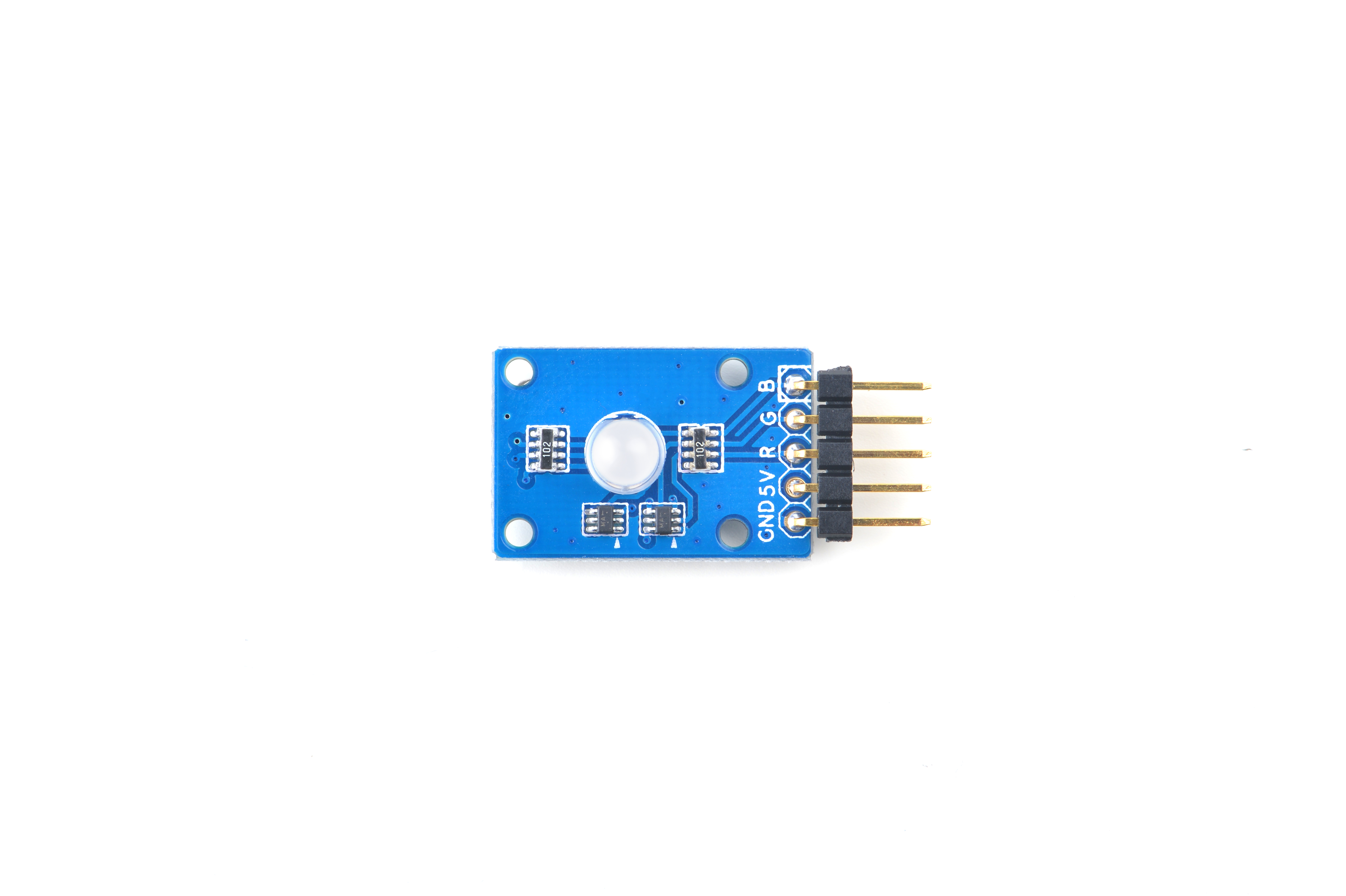
- The Matrix-RGB_LED is a RGB LED module. It has a 2.54mm pitch pin-header in which 5V is power supply, GND is ground, and R,G,B are connected to the LED’s red, green and blue pins.
- The inputs to Pin R, G and B can be either GPIO signals or PWM signals. The signal level can be either 3.3V or 5V. When the inputs to Pin R,G and B are high the LED will be the brightest.When the inputs to Pin R,G and B are low the LED will be completely off. When the inputs are PWM signals the LED's brightness can be controlled by controlling the PWM's duty cycle.
2 Features
- GPIO or PWM input, 3.3/5V, LED lightness controllable via PWM
- Small
- 2.54 mm pitch pin-header
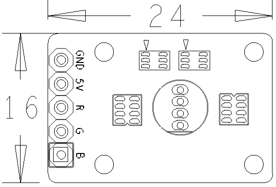
- PCB dimension(mm): 16 x 24
- Pin Description:
| Pin | Description |
| GND | Ground |
| 5V | Supply Voltage 5V |
| R | Red |
| G | Green |
| B | Blue |
3 Basic Device Operation
- In the RGB_LED module three one-color LEDs(one red,one green and one blue) are housed in a single package.These three LEDs share one common anode or cathode.When applying control signals to the other three leads their corresponding LEDs will be on. When two or three LEDs are on simultaneously a different color will be produced.You can produce different colors by adjusting PWM signals' duty cycle.
4 Applications
4.1 Connect to NanoPi M1
Refer to the following connection diagram to connect the module to the NanoPi M1:
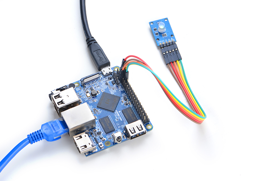
Connection Details:
| Matrix-RGBLED | NanoPi M1 |
| R | Pin7 |
| G | Pin8 |
| B | Pin10 |
| V | Pin4 |
| G | Pin6 |
4.2 Connect to NanoPi 2
Refer to the following connection diagram to connect the module to the NanoPi 2:
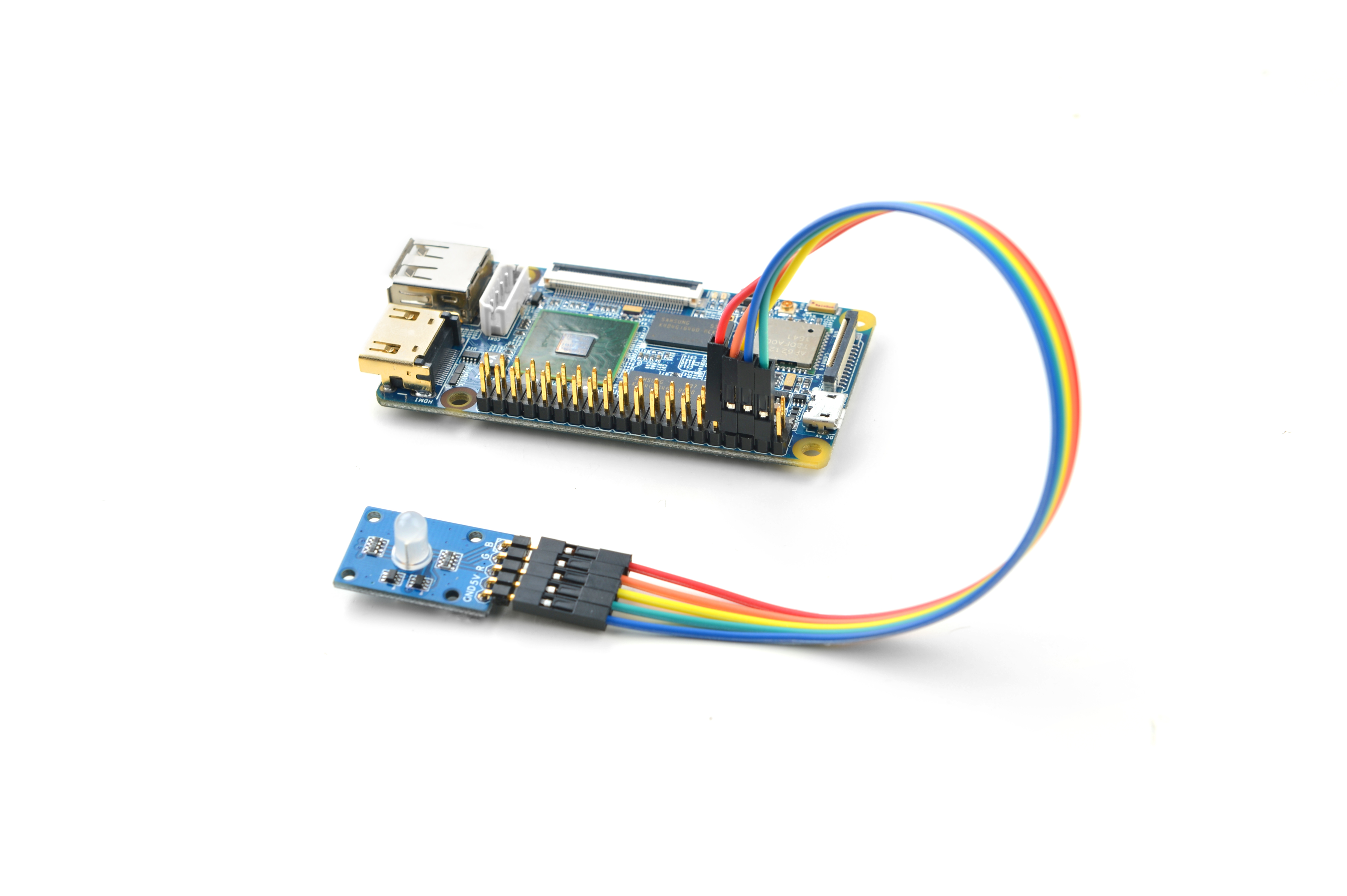
Connection Details:
| Matrix-RGBLED | NanoPi 2 |
| R | Pin7 |
| G | Pin8 |
| B | Pin10 |
| V | Pin4 |
| G | Pin6 |
4.3 Connect to NanoPi M2 / NanoPi 2 Fire
Refer to the following connection diagram to connect the module to the NanoPi M2/ NanoPi 2 Fire.
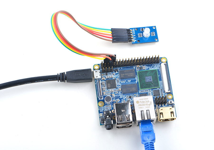
Connection Details:
| Matrix-RGBLED | NanoPi M2 |
| R | Pin7 |
| G | Pin8 |
| B | Pin10 |
| V | Pin4 |
| G | Pin6 |
4.4 Connect to NanoPC-T2
Refer to the following connection diagram to connect the module to the NanoPC-T2:
Matrix-RGBLED_NanoPC-T2
Connection Details:
| Matrix-RGBLED | NanoPC-T2 |
| R | Pin15 |
| G | Pin16 |
| B | Pin17 |
| V | Pin29 |
| G | Pin30 |
5 Compile & Run Test Program
Boot your ARM board with Debian and copy the matrix code:
$ apt-get update && apt-get install git
$ git clone https://github.com/friendlyarm/matrix.git
If your cloning is done successfully a "matrix" directory will be generated.
Compile and install Matrix:
$ cd matrix
$ make && make install
Run test program:
$ matrix-rgb_ledNote: this module is not plug and play therefore before running the module please make sure it is connected to an ARM board.
Here is what you should observe:
Set RGB LED: 0
Set RGB LED: 1
Set RGB LED: 2
Set RGB LED: 3
Set RGB LED: 4
Set RGB LED: 5
Set RGB LED: 6
Set RGB LED: 7
You will see the LED displaying different colors.
6 Code Sample
This Matrix code sample can work with all the ARM boards mentioned in this module's wiki. The name of this code sample is "matrix-rgb_led". Here is its source code:
int main(int argc, char ** argv)
{
    int ret = -1;
    int val, board;

    if ((board = boardInit()) < 0) {
        printf("Fail to init board\n");
        return -1;
    }
    if (board == BOARD_NANOPI_T2) {
        ledPin1 = GPIO_PIN(15);
        ledPin2 = GPIO_PIN(16);
        ledPin3 = GPIO_PIN(17);
    }
    if ((ret = exportGPIOPin(ledPin1)) == -1) {
        printf("exportGPIOPin(%d) failed\n", ledPin1);
    }
    if ((ret = setGPIODirection(ledPin1, GPIO_OUT)) == -1) {
        printf("setGPIODirection(%d) failed\n", ledPin1);
    }
    if ((ret = exportGPIOPin(ledPin2)) == -1) {
        printf("exportGPIOPin(%d) failed\n", ledPin2);
    }
    if ((ret = setGPIODirection(ledPin2, GPIO_OUT)) == -1) {
        printf("setGPIODirection(%d) failed\n", ledPin2);
    }
    if ((ret = exportGPIOPin(ledPin3)) == -1) {
        printf("exportGPIOPin(%d) failed\n", ledPin3);
    }
    if ((ret = setGPIODirection(ledPin3, GPIO_OUT)) == -1) {
        printf("setGPIODirection(%d) failed\n", ledPin3);
    }
    signal(SIGINT, intHandler);
    for (val = 0; val < 8; val++) {
        printf("Set RGB LED: %x\n", val);
        setRGBLED(val);
        usleep(1000 * 1000);
    }
    unexportGPIOPin(ledPin1);
    unexportGPIOPin(ledPin2);
    unexportGPIOPin(ledPin3);
    return 0;
}
For more details about this APIs called in this code sample refer to Matrix API reference manual
7 Resources
8 Update Log
8.1 June-24-2016
- Created English wiki
