Difference between revisions of "Matrix - 3-Axis Digital Compass"
(→Download Matrix Source Code) |
(→Connect to NanoPi M2 / NanoPi 2 Fire) |
||
| (10 intermediate revisions by one other user not shown) | |||
| Line 2: | Line 2: | ||
==Introduction== | ==Introduction== | ||
| − | [[File: | + | [[File:Matrix-3_Axis_Digital_Compass.jpg|thumb|3-Axis Digital Compass]] |
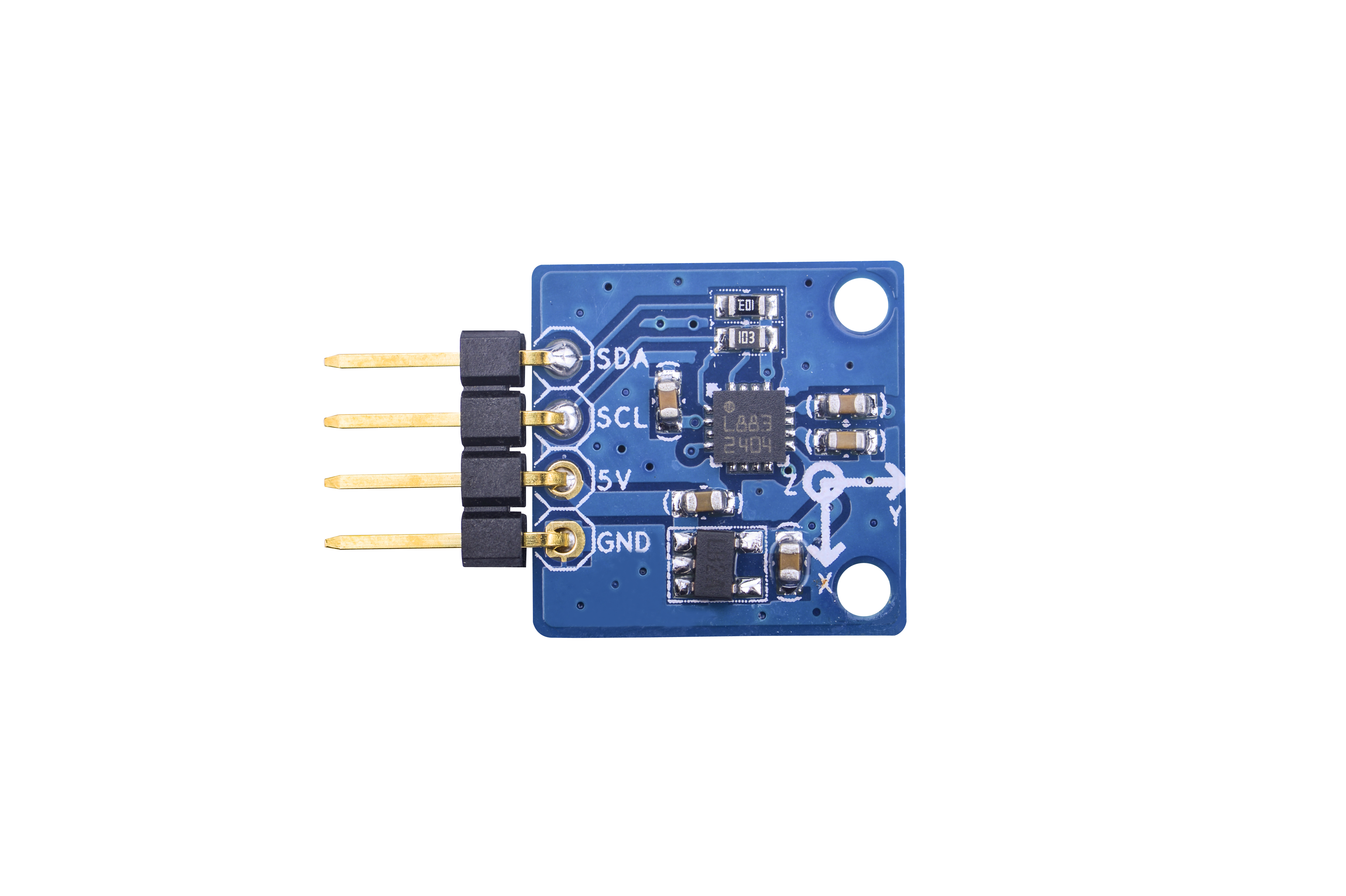
* The Matrix-3_Axis_Digital_Compass module is designed to measure the direction and functions like to a compass. | * The Matrix-3_Axis_Digital_Compass module is designed to measure the direction and functions like to a compass. | ||
* It utilizes the HMC5883L chip. The HMC5883L includes high-resolution HMC118X series magneto-resistive sensors plus an ASIC containing amplification, automatic degaussing strap drivers, offset cancellation, and a 12-bit ADC that enables 1° to 2° compass heading accuracy. It achieves 2 milli-gauss field resolution in ±8 gauss fields. These sensors’ solid-state construction with very low cross-axis sensitivity is designed to measure both the direction and the magnitude of Earth’s magnetic fields, from milli-gauss to 8 gauss. It has an I2C serial bus interface. | * It utilizes the HMC5883L chip. The HMC5883L includes high-resolution HMC118X series magneto-resistive sensors plus an ASIC containing amplification, automatic degaussing strap drivers, offset cancellation, and a 12-bit ADC that enables 1° to 2° compass heading accuracy. It achieves 2 milli-gauss field resolution in ±8 gauss fields. These sensors’ solid-state construction with very low cross-axis sensitivity is designed to measure both the direction and the magnitude of Earth’s magnetic fields, from milli-gauss to 8 gauss. It has an I2C serial bus interface. | ||
| − | * It integrates a 3.3V power conversion IC allowing it to be powered by an external 5V power source. It can be controlled by an I2C master. | + | * It integrates a 3.3V power conversion IC allowing it to be powered by an external 5V power source. It can be controlled by an I2C master. |
==Features== | ==Features== | ||
| Line 34: | Line 34: | ||
[[File:三轴重力.png|frameless|400px|三轴重力加速度]] | [[File:三轴重力.png|frameless|400px|三轴重力加速度]] | ||
| + | <!--- | ||
==Download Matrix Source Code== | ==Download Matrix Source Code== | ||
All the matrix modules' code samples are open source. They are maintained on GitHub - https://github.com/friendlyarm/matrix.git <br> | All the matrix modules' code samples are open source. They are maintained on GitHub - https://github.com/friendlyarm/matrix.git <br> | ||
Each branch in this hub contains the matrix modules' code samples for a board that the matrix modules can work with.<br> | Each branch in this hub contains the matrix modules' code samples for a board that the matrix modules can work with.<br> | ||
* The nanopi branch contains the matrix modules' code samples for the NanoPi | * The nanopi branch contains the matrix modules' code samples for the NanoPi | ||
| + | * The nanopi 2 branch contains the matrix modules' code samples for the NanoPi 2 | ||
* The tiny4412 branch contains the matrix modules' code samples for the Tiny4412 | * The tiny4412 branch contains the matrix modules' code samples for the Tiny4412 | ||
* The raspberrypi branch contains the matrix modules' code samples for the RaspberryPi | * The raspberrypi branch contains the matrix modules' code samples for the RaspberryPi | ||
| Line 52: | Line 54: | ||
</syntaxhighlight> | </syntaxhighlight> | ||
If this is successful a "matrix" directory will be generated, which will contain all the matrix modules' code samples. | If this is successful a "matrix" directory will be generated, which will contain all the matrix modules' code samples. | ||
| + | ---> | ||
| + | |||
| + | ==Applications== | ||
| + | ===Connect to NanoPi M1=== | ||
| + | Refer to the following connection diagram to connect the module to the NanoPi M1:<br> | ||
| + | [[File:Matrix-3_Axis_Digital_Compass_nanopi_m1.jpg|frameless|600px|Matrix-3_Axis_Digital_Compass_nanopi_m1]] | ||
| + | |||
| + | Connection Details: | ||
| + | {| class="wikitable" | ||
| + | |- | ||
| + | |Matrix-3_Axis_Digital_Compass || NanoPi M1 | ||
| + | |- | ||
| + | |SDA || Pin3 | ||
| + | |- | ||
| + | |SCL || Pin5 | ||
| + | |- | ||
| + | |5V || Pin4 | ||
| + | |- | ||
| + | |GND || Pin6 | ||
| + | |} | ||
| + | |||
| + | ===Connect to NanoPi 2=== | ||
| + | Refer to the following connection diagram to connect the module to the NanoPi 2:<br> | ||
| + | [[File:Matrix-3_Axis_Digital_Compass_nanopi_2.jpg|frameless|600px|Matrix-3_Axis_Digital_Compass_nanopi_2]] | ||
| + | |||
| + | Connection Details: | ||
| + | {| class="wikitable" | ||
| + | |- | ||
| + | |Matrix-3_Axis_Digital_Compass || NanoPi 2 | ||
| + | |- | ||
| + | |SDA || Pin3 | ||
| + | |- | ||
| + | |SCL || Pin5 | ||
| + | |- | ||
| + | |5V || Pin4 | ||
| + | |- | ||
| + | |GND || Pin6 | ||
| + | |} | ||
| + | |||
| + | ===Connect to NanoPi M2 / NanoPi 2 Fire=== | ||
| + | Refer to the following connection diagram to connect the module to the NanoPi M2/ NanoPi 2 Fire.<br> | ||
| + | [[File:Matrix-3_Axis_Digital_Compass_nanopi_m2.jpg|frameless|600px|Matrix-3_Axis_Digital_Compass_nanopi_m2]] | ||
| + | |||
| + | Connection Details: | ||
| + | {| class="wikitable" | ||
| + | |- | ||
| + | |Matrix-3_Axis_Digital_Compass || NanoPi M2 | ||
| + | |- | ||
| + | |SDA || Pin3 | ||
| + | |- | ||
| + | |SCL || Pin5 | ||
| + | |- | ||
| + | |5V || Pin4 | ||
| + | |- | ||
| + | |GND || Pin6 | ||
| + | |} | ||
| + | |||
| + | ===Connect to NanoPC-T2=== | ||
| + | Refer to the following connection diagram to connect the module to the NanoPC-T2<br> | ||
| + | [[File:Matrix-3_Axis_Digital_Compass_nanopc-T2.jpg|frameless|600px|Matrix-3_Axis_Digital_Compass_NanoPC-T2]] | ||
| + | |||
| + | Connection Details: | ||
| + | {| class="wikitable" | ||
| + | |- | ||
| + | |Matrix-3_Axis_Digital_Compass || NanoPC-T2 | ||
| + | |- | ||
| + | |SDA || Pin6 | ||
| + | |- | ||
| + | |SCL || Pin5 | ||
| + | |- | ||
| + | |5V || Pin29 | ||
| + | |- | ||
| + | |GND || Pin30 | ||
| + | |} | ||
| + | |||
| + | <!--- | ||
==Connect to NanoPi 2== | ==Connect to NanoPi 2== | ||
===Hardware Connection=== | ===Hardware Connection=== | ||
| Line 87: | Line 165: | ||
Note: please make sure to install the cross compiler "arm-linux-gcc-4.9.3" on your PC, which is used to compile files for the NanoPi 2.<br> | Note: please make sure to install the cross compiler "arm-linux-gcc-4.9.3" on your PC, which is used to compile files for the NanoPi 2.<br> | ||
Generated library files are under the "install/lib" directory. The test program is under the "install/usr/bin" directory. The modules are under the "modules" directory.<br> | Generated library files are under the "install/lib" directory. The test program is under the "install/usr/bin" directory. The modules are under the "modules" directory.<br> | ||
| + | The modules are under the "modules" directory. The driver's source code is in github: https://github.com/friendlyarm/linux-3.4.y.git <br> | ||
| Line 367: | Line 446: | ||
==Connect to Arduino== | ==Connect to Arduino== | ||
| + | |||
| + | ---> | ||
| + | |||
| + | ==Compile & Run Test Program== | ||
| + | Boot your ARM board with Debian and copy the matrix code: | ||
| + | <syntaxhighlight lang="bash"> | ||
| + | $ apt-get update && apt-get install git | ||
| + | $ git clone https://github.com/friendlyarm/matrix.git | ||
| + | </syntaxhighlight> | ||
| + | If your cloning is done successfully a "matrix" directory will be generated. | ||
| + | |||
| + | Compile and install Matrix: | ||
| + | <syntaxhighlight lang="bash"> | ||
| + | $ cd matrix | ||
| + | $ make && make install | ||
| + | </syntaxhighlight> | ||
| + | |||
| + | Run test program: | ||
| + | <syntaxhighlight lang="bash"> | ||
| + | $ matrix-compass | ||
| + | </syntaxhighlight> | ||
| + | Note: this module is not plug and play therefore before running the module please make sure it is connected to an ARM board.<br> | ||
| + | Here is what you should observe:<br> | ||
| + | <syntaxhighlight lang="bash"> | ||
| + | The angle is 305.2 | ||
| + | </syntaxhighlight> | ||
| + | 305.2 is the angle's value whose range is 0 ~ 360. | ||
| + | |||
| + | ==Code Sample== | ||
| + | This Matrix code sample can work with all the ARM boards mentioned in this module's wiki. The name of this code sample is "matrix-3_axis_digital_compass". Here is its source code: | ||
| + | <syntaxhighlight lang="c"> | ||
| + | int main(int argc, char ** argv) | ||
| + | { | ||
| + | int devFD; | ||
| + | double angle; | ||
| + | int i2cDev = 0; | ||
| + | |||
| + | if (boardInit() < 0) { | ||
| + | printf("Fail to init board\n"); | ||
| + | return -1; | ||
| + | } | ||
| + | |||
| + | if (argc == 2) | ||
| + | i2cDev = atoi(argv[1]); | ||
| + | if ((devFD = hmc5883Init(i2cDev)) == -1) { | ||
| + | printf("Fail to init hmc5883\n"); | ||
| + | return -1; | ||
| + | } | ||
| + | if ((angle = hmc5883Read(devFD)) != -1) { | ||
| + | printf("The angle is %.1f\n", angle); | ||
| + | } else { | ||
| + | printf("Fail to read hmc5883\n"); | ||
| + | } | ||
| + | hmc5883DeInit(devFD); | ||
| + | |||
| + | return 0; | ||
| + | } | ||
| + | </syntaxhighlight> | ||
| + | For more details about this APIs called in this code sample refer to [[Matrix API reference manual]] <br> | ||
| + | |||
==Resources== | ==Resources== | ||
[http://www51.honeywell.com/aero/common/documents/myaerospacecatalog-documents/Defense_Brochures-documents/HMC5883L_3-Axis_Digital_Compass_IC.pdf HMC5883L_3-Axis_Digital_Compass_IC.pdf] | [http://www51.honeywell.com/aero/common/documents/myaerospacecatalog-documents/Defense_Brochures-documents/HMC5883L_3-Axis_Digital_Compass_IC.pdf HMC5883L_3-Axis_Digital_Compass_IC.pdf] | ||
| + | |||
| + | ==Update Log== | ||
| + | ===Feb-23-2016=== | ||
| + | * Added the description for "NanoPi 2 branch" in Section 4 | ||
| + | * Added driver's source code location in Section 5.2 | ||
| + | |||
| + | ===June-16-2016=== | ||
| + | * Re-organized and simplified wiki | ||
Latest revision as of 08:50, 7 July 2016
Contents
1 Introduction
- The Matrix-3_Axis_Digital_Compass module is designed to measure the direction and functions like to a compass.
- It utilizes the HMC5883L chip. The HMC5883L includes high-resolution HMC118X series magneto-resistive sensors plus an ASIC containing amplification, automatic degaussing strap drivers, offset cancellation, and a 12-bit ADC that enables 1° to 2° compass heading accuracy. It achieves 2 milli-gauss field resolution in ±8 gauss fields. These sensors’ solid-state construction with very low cross-axis sensitivity is designed to measure both the direction and the magnitude of Earth’s magnetic fields, from milli-gauss to 8 gauss. It has an I2C serial bus interface.
- It integrates a 3.3V power conversion IC allowing it to be powered by an external 5V power source. It can be controlled by an I2C master.
2 Features
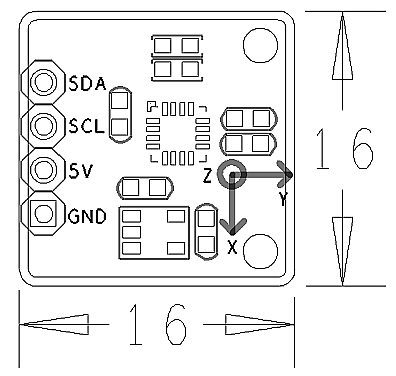
- I2C,3.3V
- 1° to 2° compass heading accuracy
- 2.54 mm spacing pin
- PCB Dimension(mm): 16 x 16
- Pin Description:
| Pin | Description |
| SDA | I2C SDA |
| SCL | I2C SCL |
| 5V | Supply Voltage 5V |
| GND | Ground |
3 Basic Device Operation
- The Honeywell HMC5883L magnetoresistive sensor circuit is a trio of sensors and application specific support circuits to measure magnetic fields. With power supply applied, the sensor converts any incident magnetic field in the sensitive axis directions to a differential voltage output. The magnetoresistive sensors are made of a nickel-iron (Permalloy) thin-film and patterned as a resistive strip element. In the presence of a magnetic field, a change in the bridge resistive elements causes a corresponding change in voltage across the bridge outputs. These resistive elements are aligned together to have a common sensitive axis (indicated by arrows in the pinout diagram) that will provide positive voltage change with magnetic fields increasing in the sensitive direction. Because the output is only proportional to the magnetic field component along its axis, additional sensor bridges are placed at orthogonal directions to permit accurate measurement of magnetic field in any orientation.
- The HMC5883L communicates via a two-wire I2C bus system as a slave device. It has 8-bit read address and 8-bit write address. This device supports standard and fast modes, 100kHz and 400kHz, respectively, but does not support the high speed mode (Hs). The bus bit format is an 8-bit Data/Address send and a 1-bit acknowledge bit. The format of the data bytes (payload) shall be case sensitive ASCII characters or binary data to the HMC5883L slave, and binary data returned. Negative binary values will be in two’s complement form. The default (factory) HMC5883L 8-bit slave address is 0x3C for write operations, or 0x3D for read operations.
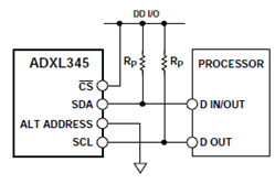
- The module has an I2C interface which complies to the I2C standard protocol and the connection diagram is as follows
4 Applications
4.1 Connect to NanoPi M1
Refer to the following connection diagram to connect the module to the NanoPi M1:
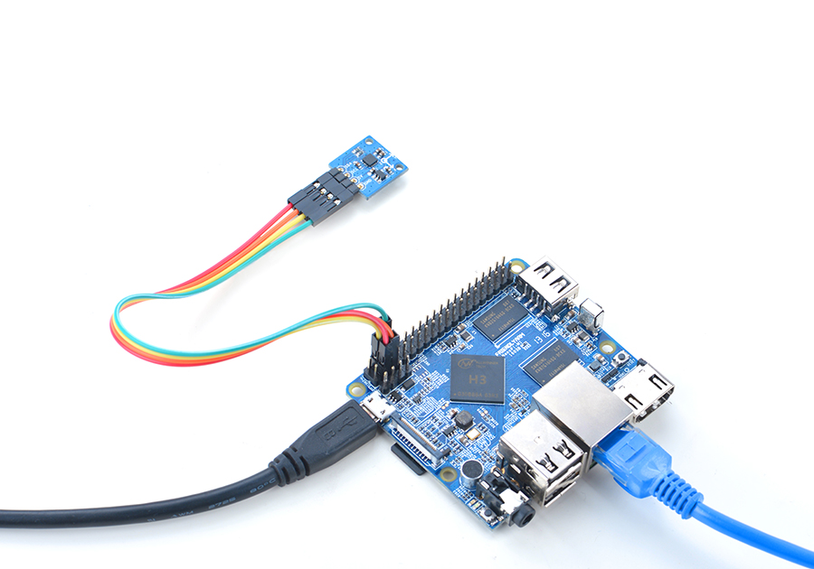
Connection Details:
| Matrix-3_Axis_Digital_Compass | NanoPi M1 |
| SDA | Pin3 |
| SCL | Pin5 |
| 5V | Pin4 |
| GND | Pin6 |
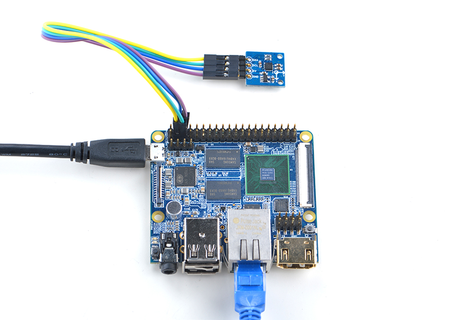
4.2 Connect to NanoPi 2
Refer to the following connection diagram to connect the module to the NanoPi 2:
Connection Details:
| Matrix-3_Axis_Digital_Compass | NanoPi 2 |
| SDA | Pin3 |
| SCL | Pin5 |
| 5V | Pin4 |
| GND | Pin6 |
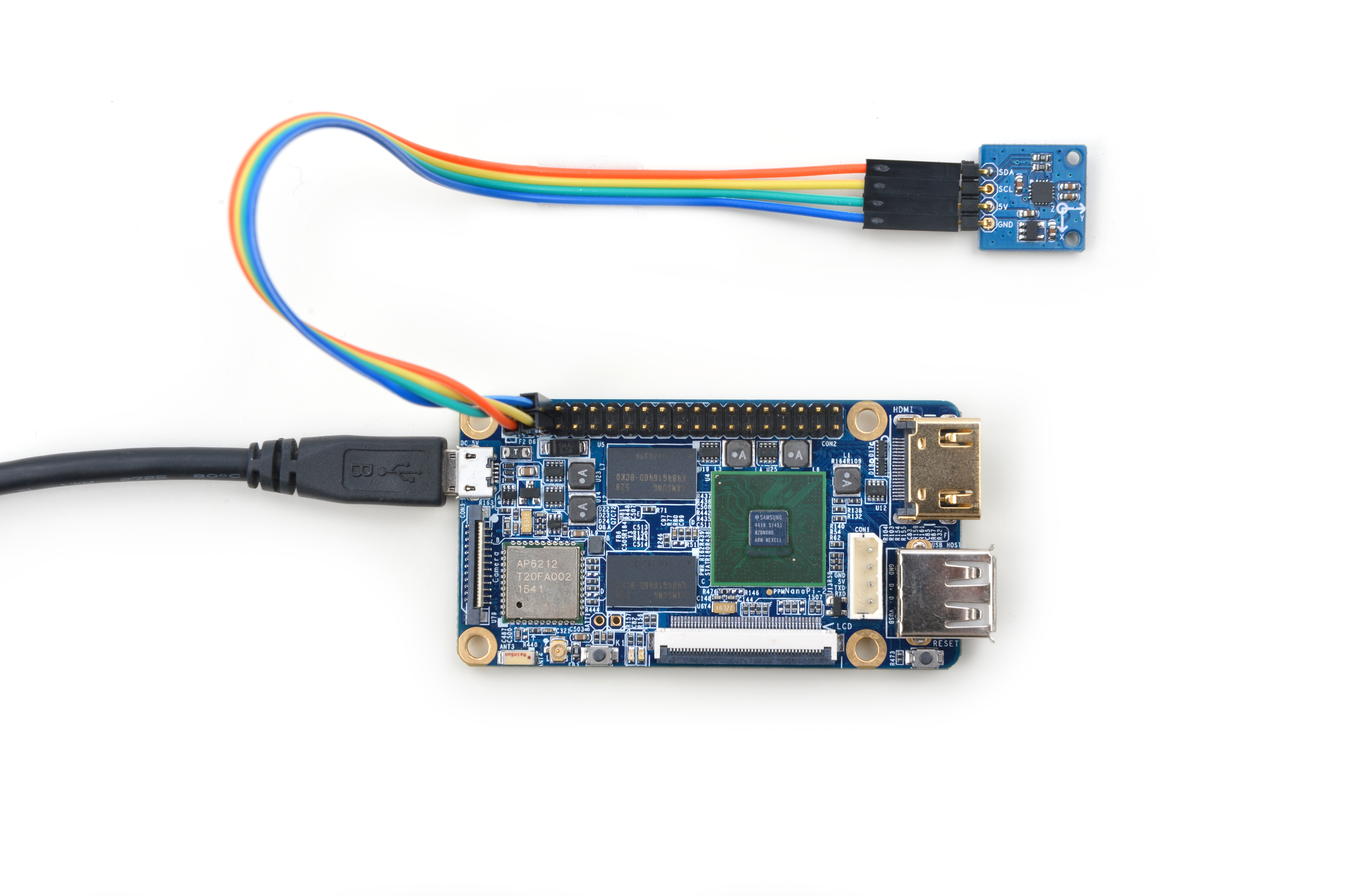
4.3 Connect to NanoPi M2 / NanoPi 2 Fire
Refer to the following connection diagram to connect the module to the NanoPi M2/ NanoPi 2 Fire.
Connection Details:
| Matrix-3_Axis_Digital_Compass | NanoPi M2 |
| SDA | Pin3 |
| SCL | Pin5 |
| 5V | Pin4 |
| GND | Pin6 |
4.4 Connect to NanoPC-T2
Refer to the following connection diagram to connect the module to the NanoPC-T2
Matrix-3_Axis_Digital_Compass_NanoPC-T2
Connection Details:
| Matrix-3_Axis_Digital_Compass | NanoPC-T2 |
| SDA | Pin6 |
| SCL | Pin5 |
| 5V | Pin29 |
| GND | Pin30 |
5 Compile & Run Test Program
Boot your ARM board with Debian and copy the matrix code:
$ apt-get update && apt-get install git
$ git clone https://github.com/friendlyarm/matrix.git
If your cloning is done successfully a "matrix" directory will be generated.
Compile and install Matrix:
$ cd matrix
$ make && make install
Run test program:
$ matrix-compassNote: this module is not plug and play therefore before running the module please make sure it is connected to an ARM board.
Here is what you should observe:
The angle is 305.2305.2 is the angle's value whose range is 0 ~ 360.
6 Code Sample
This Matrix code sample can work with all the ARM boards mentioned in this module's wiki. The name of this code sample is "matrix-3_axis_digital_compass". Here is its source code:
int main(int argc, char ** argv)
{
    int devFD;
    double angle;
    int i2cDev = 0;

    if (boardInit() < 0) {
        printf("Fail to init board\n");
        return -1;
    }

    if (argc == 2)
        i2cDev = atoi(argv[1]);
    if ((devFD = hmc5883Init(i2cDev)) == -1) {
        printf("Fail to init hmc5883\n");
        return -1;
    }
    if ((angle = hmc5883Read(devFD)) != -1) {
        printf("The angle is %.1f\n", angle);
    } else {
        printf("Fail to read hmc5883\n");
    }
    hmc5883DeInit(devFD);

    return 0;
}
For more details about this APIs called in this code sample refer to Matrix API reference manual
7 Resources
HMC5883L_3-Axis_Digital_Compass_IC.pdf
8 Update Log
8.1 Feb-23-2016
- Added the description for "NanoPi 2 branch" in Section 4
- Added driver's source code location in Section 5.2
8.2 June-16-2016
- Re-organized and simplified wiki
