Difference between revisions of "Matrix - 2'8 SPI Key TFT/zh"
(updated by API) |
|||
| (91 intermediate revisions by 4 users not shown) | |||
| Line 2: | Line 2: | ||
==介绍== | ==介绍== | ||
| − | [[File:Matrix-2'8_SPI_Key_TFT.png|thumb|]] | + | [[File:Matrix-2'8_SPI_Key_TFT.png|thumb|正面]] |
| − | * | + | [[File:Matrix-2'8_SPI_Key_TFT2.png|thumb|背面]] |
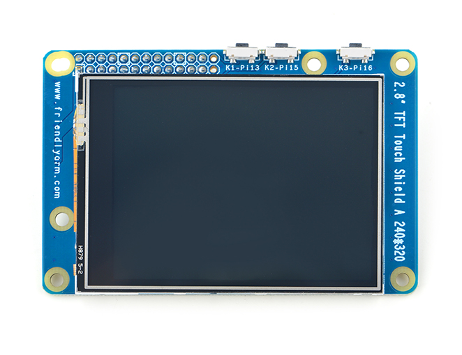
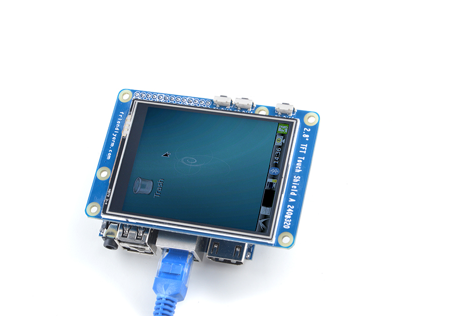
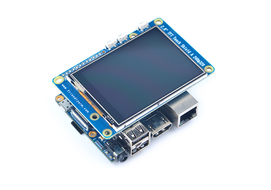
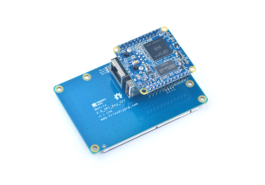
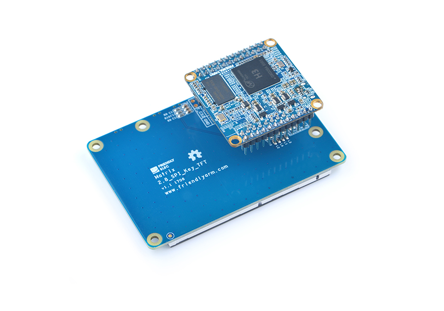
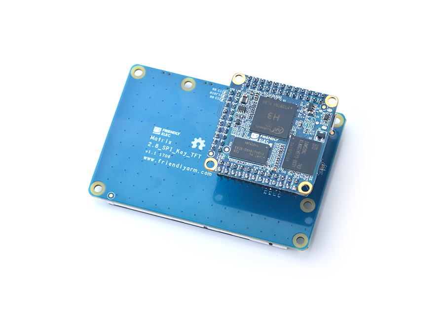
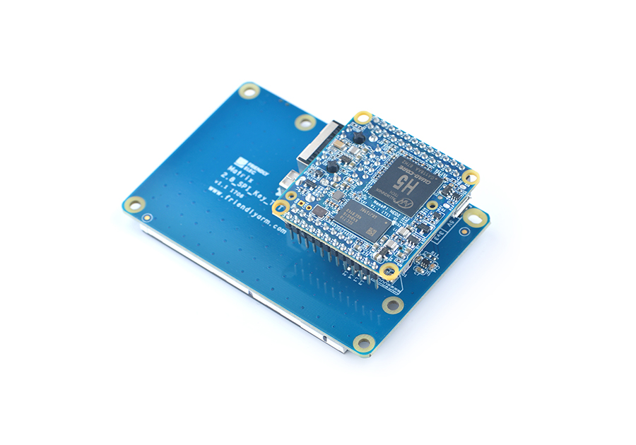
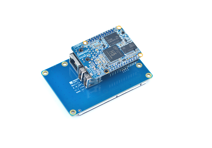
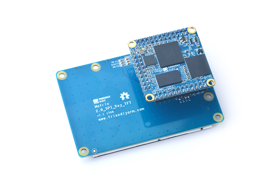
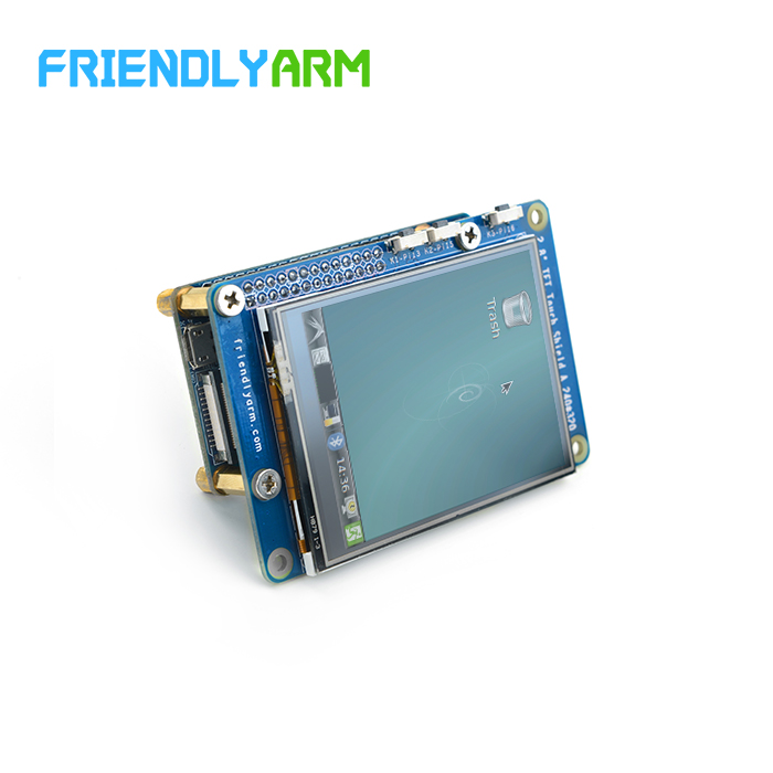
| + | *Matrix-2'8_SPI_Key_TFT模块是一款2.8英寸的TFT 触摸LCD,模块采用ST7789V驱动IC和XPT2046电阻式触摸IC,屏幕分辨率为240*320,采用SPI控制接口,模块还包含3个独立按键,可根据需要自定义功能。 | ||
| + | *详细规格如下所示: | ||
| + | {| class="wikitable" | ||
| + | |- | ||
| + | |LCD尺寸||2.8寸 | ||
| + | |- | ||
| + | |显示区域||57.6mm*43.2mm | ||
| + | |- | ||
| + | |驱动IC||ST7789V | ||
| + | |- | ||
| + | |分辨率||240*320(RGB) | ||
| + | |- | ||
| + | |接口方式||SPI | ||
| + | |- | ||
| + | |工作电压||5V | ||
| + | |- | ||
| + | |背光电压||5V | ||
| + | |- | ||
| + | |触摸屏类型||电阻式,钢化玻璃触摸屏 | ||
| + | |- | ||
| + | |} | ||
| + | 模块上电默认打开背光,可通过置低LED_EN引脚关闭背光。如果需要关闭上电打开背光,只需要拿到电路板上的R12电阻,再通过置高LED_EN引脚打开背光; | ||
| + | |||
==特性== | ==特性== | ||
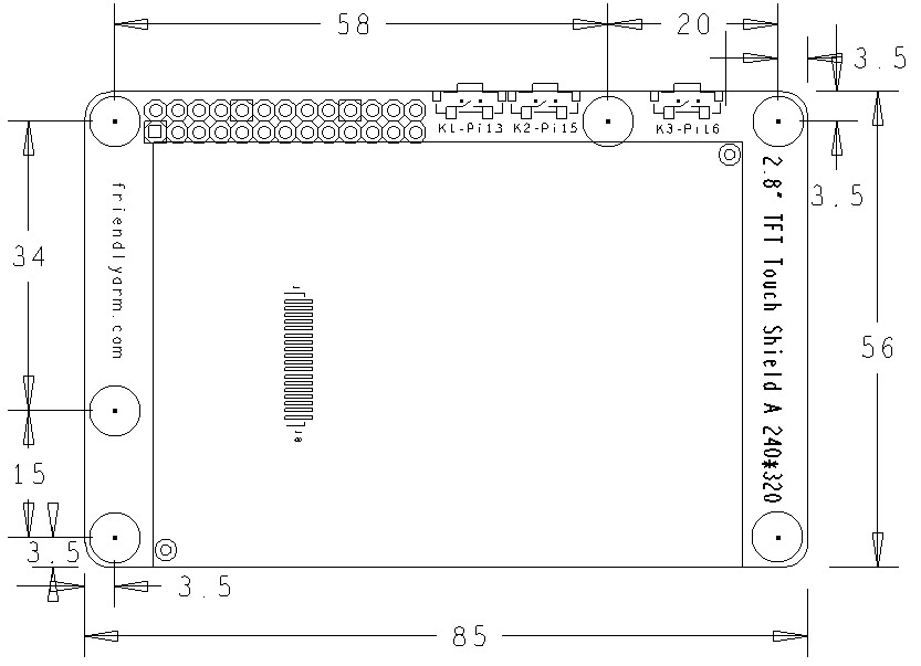
* PCB尺寸(mm): | * PCB尺寸(mm): | ||
| Line 9: | Line 32: | ||
* 引脚说明: | * 引脚说明: | ||
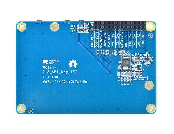
| + | Matrix-2'8_SPI_Key_TFT目前已经推出过2个版本,引脚定义如下: | ||
{| class="wikitable" | {| class="wikitable" | ||
|- | |- | ||
| − | | | + | | style="background: PaleTurquoise; color: black" colspan="4"| '''Matrix-2'8_SPI_Key_TFT-1706''' |
|- | |- | ||
| − | | | + | |Pin# || Name ||Pin# || Name |
|- | |- | ||
| − | | | + | |1 || VDD_3.3V ||2 || VDD_5V |
| − | | | + | |
| − | | | + | |
|- | |- | ||
| − | | | + | |3 || NC ||4 || VDD_5V |
|- | |- | ||
| − | | | + | |5 || NC ||6 || GND |
| − | | | + | |
| − | | | + | |
|- | |- | ||
| − | | | + | |7 || LCD_RESET ||8 || NC |
|- | |- | ||
| − | | | + | |9 || GND ||10 || NC |
| + | |- | ||
| + | |11 || LED_EN ||12 || T_CS | ||
| + | |- | ||
| + | |13 || KEY_1 ||14 || GND | ||
| + | |- | ||
| + | |15 || KEY_2 ||16 || KEY_3 | ||
| + | |- | ||
| + | |17 || VDD_3.3V ||18 || T_IRQ | ||
| + | |- | ||
| + | |19 || SPI_MOSI ||20 || GND | ||
| + | |- | ||
| + | |21 || SPI_MISO ||22 || LCD_D/C | ||
| + | |- | ||
| + | |23 || SPI_CLK ||24 || LCD_CS | ||
| + | |- | ||
| + | |25 || GND ||26 || NC | ||
|- | |- | ||
| − | | | + | |} |
| + | |||
| + | {| class="wikitable" | ||
|- | |- | ||
| − | | | + | | style="background: PaleTurquoise; color: black" colspan="4"| '''Matrix-2'8_SPI_Key_TFT-1512''' |
|- | |- | ||
| − | | | + | |Pin# || Name ||Pin# || Name |
| + | |- | ||
| + | |1 || VDD_3.3V ||2 || VDD_5V | ||
| + | |- | ||
| + | |3 || NC ||4 || VDD_5V | ||
| + | |- | ||
| + | |5 || NC ||6 || GND | ||
| + | |- | ||
| + | |7 || LCD_RESET ||8 || NC | ||
| + | |- | ||
| + | |9 || GND ||10 || NC | ||
| + | |- | ||
| + | |11 || LED_EN ||12 || NC | ||
| + | |- | ||
| + | |13 || KEY_1 ||14 || GND | ||
| + | |- | ||
| + | |15 || KEY_2 ||16 || KEY_3 | ||
| + | |- | ||
| + | |17 || VDD_3.3V ||18 || T_IRQ | ||
| + | |- | ||
| + | |19 || SPI_MOSI ||20 || GND | ||
| + | |- | ||
| + | |21 || SPI_MISO ||22 || LCD_D/C | ||
| + | |- | ||
| + | |23 || SPI_CLK ||24 || LCD_CS | ||
| + | |- | ||
| + | |25 || GND ||26 || T_CS | ||
|- | |- | ||
|} | |} | ||
| − | = | + | <span style="color:#ff0000"> <br> Matrix-2'8_SPI_Key_TFT-1706将触摸芯片的使能引脚T_CS从Pin26修改为Pin12,这样修改之后NEO/NEO2/NEO-Plus2等引脚是24Pin兼容的开发板就能正常使用触摸芯片了。 <br></span> |
| − | == | + | ==支持该配件的开发板型号和软件版本== |
| − | + | {| class="wikitable" | |
| − | + | |- | |
| − | + | |序号 ||CPU型号|| 开发板型号 || 软件版本 | |
| − | + | |- | |
| − | + | |1 ||H3||NanoPi NEO/NEO Air/NEO Core/M1/M1 Plus|| 全志原厂Linux-3.4内核和开源社区Linux-4.x主线内核 | |
| − | + | |- | |
| + | |2 ||H5||NanoPi NEO2/NEO Plus2/NEO Core2 || 开源社区Linux-4.x主线内核 | ||
| + | |- | ||
| + | |3 ||S5P4418||NanoPi2/NanoPi M2/NanoPi2 Fire || 三星原厂Linux-3.4内核 | ||
| + | |- | ||
| + | |} | ||
| − | + | ==硬件连接== | |
| − | + | ===H3系列=== | |
| − | + | 连接NanoPi M1:<br> | |
| − | < | + | [[File:Matrix-2'8_SPI_Key_TFT_nanopi_m1.jpg|frameless|500px|Matrix-2'8_SPI_Key_TFT_nanopi_m1]]<br> |
| − | + | 连接NanoPi M1 Plus:<br> | |
| − | < | + | [[File:Matrix-2'8_SPI_Key_TFT_nanopi_m1_plus.jpg|frameless|500px|Matrix-2'8_SPI_Key_TFT_nanopi_m1_plus]]<br> |
| − | + | ||
| − | < | + | |
| − | + | ||
| − | + | 连接NanoPi NEO:<br> | |
| − | + | [[File:Matrix-2'8_SPI_Key_TFT_nanopi_neo.jpg|frameless|500px|Matrix-2'8_SPI_Key_TFT_nanopi_neo]]<br> | |
| − | + | ||
| − | [[File:Matrix-2' | + | |
| − | + | 连接NanoPi NEO Air:<br> | |
| − | {| class="wikitable" | + | [[File:Matrix-2'8_SPI_Key_TFT_nanopi_neo_air.jpg|frameless|500px|Matrix-2'8_SPI_Key_TFT_nanopi_neo_air]]<br> |
| + | |||
| + | 连接NanoPi NEO Core:<br> | ||
| + | [[File:Matrix-2'8_SPI_Key_TFT_nanopi_neo_core.jpg|frameless|500px|Matrix-2'8_SPI_Key_TFT_nanopi_neo_core]]<br> | ||
| + | |||
| + | ===H5系列=== | ||
| + | 连接NanoPi NEO2 :<br> | ||
| + | [[File:Matrix-2'8_SPI_Key_TFT_nanopi_neo2.jpg|frameless|600px|Matrix-2'8_SPI_Key_TFT_nanopi_neo2]]<br> | ||
| + | |||
| + | 连接NanoPi NEO Plus2:<br> | ||
| + | [[File:Matrix-2'8_SPI_Key_TFT_nanopi_neo2-plus.jpg|frameless|600px|Matrix-2'8_SPI_Key_TFT_nanopi_neo-plus2]]<br> | ||
| + | |||
| + | 连接NanoPi NEO Core2:<br> | ||
| + | [[File:Matrix-2'8_SPI_Key_TFT_nanopi_neo_core2.jpg|frameless|500px|Matrix-2'8_SPI_Key_TFT_nanopi_neo_core2]]<br> | ||
| + | |||
| + | ===S5P4418系列=== | ||
| + | 连接NanoPi2:<br> | ||
| + | [[File:Matrix-2'8_SPI_Key_TFT_nanopi2.jpg|frameless|600px|Matrix-2'8_SPI_Key_TFT_nanopi2]]<br> | ||
| + | |||
| + | 连接NanoPi M2 / NanoPi2 Fire:<br> | ||
| + | [[File:Matrix-2'8_SPI_Key_TFT_nanopi_m2.jpg|frameless|600px|Matrix-2'8_SPI_Key_TFT_nanopi_m2]]<br> | ||
| + | NanoPi M2和NanoPi 2 Fire的40 Pin引脚定义是一模一样的,所以它们操作Matrix配件的步骤是一样的,这里仅以NanoPi M2为例。<br> | ||
| + | |||
| + | ==使用默认使能Matrix-2'8_SPI_Key_TFT的ROM== | ||
| + | ::{| class="wikitable" | ||
|- | |- | ||
| − | | | + | |Board Type||CPU Model||Download Link to Image File||Image File |
|- | |- | ||
| − | | | + | |NanoPi NEO|| H3 || [http://download.friendlyelec.com/nanopineo Download]|| official-ROMs/accessory-ROMs/nanopi-neo_sd_ubuntu-tft_4.14_YYYYMMDD.img.zip |
|- | |- | ||
| − | | | + | |NanoPi NEO Air|| H3 ||[http://download.friendlyelec.com/nanopineoair Download] || official-ROMs/accessory-ROMs/nanopi-neo-air_sd_ubuntu-tft_4.14_YYYYMMDD.img.zip |
| − | | | + | |
| − | | | + | |
|- | |- | ||
| − | | | + | |NanoPi M1|| H3 ||[http://download.friendlyelec.com/nanopim1 Download] || official-ROMs/accessory-ROMs/nanopi-m1_sd_ubuntu-tft_4.14_YYYYMMDD.img.zip |
|- | |- | ||
| − | | | + | |NanoPi M1 Plus|| H3 ||[http://download.friendlyelec.com/nanopim1plus Download] || official-ROMs/accessory-ROMs/nanopi-m1-plus_sd_ubuntu-tft_4.14_YYYYMMDD.img.zip |
| − | | | + | |
| − | | | + | |
|- | |- | ||
| − | | | + | |NanoPi NEO Core|| H3 ||[http://download.friendlyelec.com/nanopineocore Download] || official-ROMs/accessory-ROMs/nanopi-neo-core_sd_ubuntu-tft_4.14_YYYYMMDD.img.zip |
|- | |- | ||
| − | | | + | |NanoPi NEO2|| H5 ||[http://download.friendlyelec.com/nanopineo2 Download] || official-ROMs/accessory-ROMs/nanopi-neo2_sd_ubuntu-tft_4.14_YYYYMMDD.img.zip |
| − | | | + | |
| − | | | + | |
|- | |- | ||
| − | | | + | |NanoPi NEO Plus2|| H5 ||[http://download.friendlyelec.com/nanopineoplus2 Download] || official-ROMs/accessory-ROMs/nanopi-neo-plus2_sd_ubuntu-tft_4.14_YYYYMMDD.img.zip |
| + | |- | ||
| + | |NanoPi NEO Core2|| H5 ||[http://download.friendlyelec.com/nanopineocore2 Download] || official-ROMs/accessory-ROMs/nanopi-neo-core2_sd_ubuntu-tft_4.14_YYYYMMDD.img.zip | ||
| + | |- | ||
| + | |NanoPi K1 Plus|| H5 ||[http://download.friendlyelec.com/nanopik1plus Download] || official-ROMs/accessory-ROMs/nanopi-k1-plus_sd_ubuntu-tft_4.14_YYYYMMDD.img.zip | ||
|- | |- | ||
| − | |||
| − | |||
|} | |} | ||
| − | === | + | ==使能Matrix-2'8_SPI_Key_TFT== |
| − | + | ===H3/H5平台=== | |
| − | + | 注意:以下测试方法适用于测试Matrix-2'8_SPI_Key_TFT-1706版本的硬件,对于Matrix-2'8_SPI_Key_TFT-1512(丝印T28-02 1512)硬件,请按照本章节末尾的说明自行修改软件,将触摸芯片的使能引脚设置为Pin26。<br><br> | |
| + | |||
| + | ====Linux-4.14==== | ||
| + | =====使用npi-config使能Matrix-2'8_SPI_Key_TFT===== | ||
| + | 当使用的开发板为H3或者H5系列时,假设使用的ROM是基于Linux-4.x主线内核的Ubuntu-Core with Qt-Embedded系统,那么首先需要通过npi-config工具来使能Matrix-2'8_SPI_Key_TFT。启动系统,在root用户下执行下列命令运行npi-config: | ||
<syntaxhighlight lang="bash"> | <syntaxhighlight lang="bash"> | ||
| − | $ | + | $ npi-config |
| − | + | ||
| − | + | ||
</syntaxhighlight> | </syntaxhighlight> | ||
| − | + | 然后依次进入下列菜单项:<br> | |
| − | + | [[File:tft-1.png|frameless|1000px|tft-1]]<br> | |
| + | 进入SPI菜单:<br> | ||
| + | [[File:tft-2.png|frameless|1000px|tft-2]]<br> | ||
| + | 选择是否使能SPI0:<br> | ||
| + | [[File:tft-3.png|frameless|1000px|tft-3]]<br> | ||
| + | 选择enable SPI0后,再选择SPI0上连接的设备为Matrix-2'8_SPI_Key_TFT:<br> | ||
| + | [[File:tft-4.png|frameless|1000px|tft-4]]<br> | ||
| + | 最后返回主菜单,选择<Finish>,然后根据提示重启系统。重新启动系统后,执行下列命令检查Matrix-2'8_SPI_Key_TFT的显示芯片和触摸芯片是否被使能: | ||
<syntaxhighlight lang="bash"> | <syntaxhighlight lang="bash"> | ||
| − | $ | + | $ ls /dev/fb-st7789s |
| − | + | /dev/fb-st7789s | |
| − | + | ||
</syntaxhighlight> | </syntaxhighlight> | ||
| − | + | /dev/fb-st7789s就是显示芯片的framebuffer设备节点。 | |
| − | + | ||
| − | + | ||
| − | + | ||
<syntaxhighlight lang="bash"> | <syntaxhighlight lang="bash"> | ||
| − | $ | + | $ ls /dev/input/ts-ads7846 |
| + | /dev/input/ts-ads7846 | ||
</syntaxhighlight> | </syntaxhighlight> | ||
| − | + | /dev/input/ts-ads7846就是触摸芯片的设备节点。 | |
| + | 第一次进入系统时会进行触摸校准,根据屏幕的提示点击5个点完成校准即可。<br> | ||
| + | [[File:tslib.png|frameless|1000px|tft-tslib]]<br> | ||
| + | 注意:在Linux4.x主线内核中,默认支持的是使用Pin12作为触摸芯片的使能引脚的Matrix-2'8_SPI_Key_TFT-1706版本。<br> | ||
| + | 通过npi-config使能Matrix-2'8_SPI_Key_TFT后,系统会将默认的登录显示设备设置为Matrix-2'8_SPI_Key_TFT。如果你想开机运行Qt-demo程序,可以在npi-config中进行如下配置,进入Boot Options菜单:<br> | ||
| + | [[File:tft-qt-demo-1.png|frameless|1000px|tft-qt-demo-1]]<br> | ||
| + | 进入Autologin菜单:<br> | ||
| + | [[File:tft-qt-demo-2.png|frameless|1000px|tft-qt-demo-2]]<br> | ||
| + | 进去Qt/Embedded菜单:<br> | ||
| + | [[File:tft-qt-demo-3.png|frameless|1000px|tft-qt-demo-3]]<br> | ||
| + | 使能Qt/E Demo:<br> | ||
| + | [[File:tft-qt-demo-4.png|frameless|1000px|tft-qt-demo-4]]<br> | ||
| + | 最后返回主菜单,选择<Finish>,然后根据提示重启系统。重新启动系统后,屏幕上会自动运行Qt/E demo,效果如下:<br> | ||
| + | [[File:qt-demo-status.png|frameless|600px|qt-demo-status]]<br> | ||
| + | |||
| + | =====控制背光===== | ||
<syntaxhighlight lang="bash"> | <syntaxhighlight lang="bash"> | ||
| − | + | $ echo 1 >/sys/class/backlight/fb_st7789v/bl_power # 关闭背光 | |
| + | $ echo 0 >/sys/class/backlight/fb_st7789v/bl_power # 打开背光 | ||
</syntaxhighlight> | </syntaxhighlight> | ||
| − | |||
| − | === | + | =====对于Matrix-2'8_SPI_Key_TFT-1512的额外设置===== |
| − | + | 对于使用Matrix-2'8_SPI_Key_TFT-1512(丝印T28-02 1512)+ NanoPi M1/NanoPi M1 Plus的用户,需要自行修改内核代码选择使用Pin26作为触摸使能引脚才能正常使用触摸功能。<br> | |
| + | 假设你已经参考H3 主线内核的维基[[Mainline U-boot & Linux]]成功克隆并编译了Linux内核,则还需要修改下列代码: | ||
| + | 修改下列代码: | ||
<syntaxhighlight lang="bash"> | <syntaxhighlight lang="bash"> | ||
| − | $ | + | $ vi linux/arch/arm/boot/dts/sun8i-h3-nanopi |
| + | ... | ||
| + | spi0_cs_pins: spi0_cs_pins { | ||
| + | pins = "PC3", "PA6"; | ||
| + | function = "gpio_out"; | ||
| + | }; | ||
| + | ... | ||
| + | &spi0 { | ||
| + | ... | ||
| + | cs-gpios = <&pio 2 3 GPIO_ACTIVE_HIGH>, <&pio 0 6 GPIO_ACTIVE_HIGH>; | ||
| + | ... | ||
</syntaxhighlight> | </syntaxhighlight> | ||
| − | + | 其中<&pio 0 6 GPIO_ACTIVE_HIGH>表示使用GPIOA6(Pin12)作为触摸使能引脚,将其修改为GPIOA17(Pin26): | |
<syntaxhighlight lang="bash"> | <syntaxhighlight lang="bash"> | ||
| − | + | ... | |
| − | + | spi0_cs_pins: spi0_cs_pins { | |
| − | + | pins = "PC3", "PA17"; | |
| − | + | function = "gpio_out"; | |
| − | + | }; | |
| − | + | ... | |
| + | &spi0 { | ||
| + | ... | ||
| + | cs-gpios = <&pio 2 3 GPIO_ACTIVE_HIGH>, <&pio 0 17 GPIO_ACTIVE_HIGH>; | ||
| + | ... | ||
</syntaxhighlight> | </syntaxhighlight> | ||
| − | + | 然后重新编译内核,拷贝arch/arm/boot/dts/目录下的sun8i-h3-nanopi-m1.dtb/sun8i-h3-nanopi-m1-plus.dtb到TF卡boot分区下,重新启动板子即可。 | |
| − | == | + | ====Linux 3.4==== |
| − | === | + | 启动开发板并运行FriendlyCoore系统,进入系统后克隆Matrix代码仓库: |
| − | + | ||
| − | + | ||
| − | + | ||
<syntaxhighlight lang="bash"> | <syntaxhighlight lang="bash"> | ||
| − | $ git clone https://github.com/friendlyarm/ | + | $ apt-get update && apt-get install git |
| − | + | $ git clone https://github.com/friendlyarm/matrix.git | |
| − | + | ||
| − | + | ||
| − | + | ||
| − | + | ||
</syntaxhighlight> | </syntaxhighlight> | ||
| + | 克隆完成后会得到一个名为matrix的目录。 | ||
| − | + | 编译并运行Qt测试程序: | |
| − | + | ||
| − | + | ||
| − | + | ||
| − | + | ||
| − | + | ||
| − | + | ||
| − | + | ||
| − | + | ||
| − | + | ||
| − | + | ||
| − | + | ||
| − | + | ||
| − | + | ||
| − | + | ||
| − | + | ||
| − | + | ||
| − | + | ||
| − | + | ||
| − | + | ||
| − | + | ||
| − | + | ||
| − | + | ||
| − | + | ||
| − | + | ||
| − | + | ||
| − | + | ||
| − | + | ||
| − | + | ||
| − | + | ||
| − | + | ||
| − | + | ||
| − | + | ||
| − | + | ||
| − | + | ||
<syntaxhighlight lang="bash"> | <syntaxhighlight lang="bash"> | ||
| − | + | cd matrix/demo/nanopi-status | |
| − | + | ./build.sh | |
| + | ./run.sh /dev/fb-st7789s | ||
</syntaxhighlight> | </syntaxhighlight> | ||
| − | + | nanopi-status是一个简单的Qt程序,可用于显示系统的基本信息,效果如下:<br> | |
| − | + | [[File:st7789s-status.png|frameless|600px|st7789s-status]]<br> | |
| − | + | 脚本run.sh会先加载tft屏的驱动模块然后运行Qt程序,驱动模块加载成功后会生成设备节点/dev/fb-st7789s,下列命令可以确定驱动模块是否成功加载: | |
| − | + | ||
<syntaxhighlight lang="bash"> | <syntaxhighlight lang="bash"> | ||
| − | + | lsmod | |
| − | + | Module Size Used by | |
| − | + | fbtft_device 29235 0 | |
</syntaxhighlight> | </syntaxhighlight> | ||
| − | + | 在确定tft驱动模块已加载的前提下,运行下列命令可以显示三原色: | |
| − | + | ||
| − | + | ||
| − | + | ||
<syntaxhighlight lang="bash"> | <syntaxhighlight lang="bash"> | ||
| − | + | cd matrix/demo/matrix-lcdtest | |
| − | + | make | |
| + | export LCDSET_FB_DEV=/dev/fb-st7789s | ||
| + | ./matrix-lcdtest | ||
</syntaxhighlight> | </syntaxhighlight> | ||
| − | + | 三原色可以呈现出屏幕的最佳显示效果。 | |
| − | + | ||
| − | + | ||
| − | + | ||
| − | |||
| − | + | {{S5Pxx18-SPI-2.8TFT/zh}} | |
==相关资料== | ==相关资料== | ||
| + | *[Schematic]([http://wiki.friendlyelec.com/wiki/images/1/1c/SCHEMATIC1_W28-02.pdf Matrix - 2'8 SPI Key TFT-Schematic.pdf]) | ||
Latest revision as of 07:17, 21 February 2022
Contents
1 介绍
- Matrix-2'8_SPI_Key_TFT模块是一款2.8英寸的TFT 触摸LCD,模块采用ST7789V驱动IC和XPT2046电阻式触摸IC,屏幕分辨率为240*320,采用SPI控制接口,模块还包含3个独立按键,可根据需要自定义功能。
- 详细规格如下所示:
| LCD尺寸 | 2.8寸 |
| 显示区域 | 57.6mm*43.2mm |
| 驱动IC | ST7789V |
| 分辨率 | 240*320(RGB) |
| 接口方式 | SPI |
| 工作电压 | 5V |
| 背光电压 | 5V |
| 触摸屏类型 | 电阻式,钢化玻璃触摸屏 |
模块上电默认打开背光,可通过置低LED_EN引脚关闭背光。如果需要关闭上电打开背光,只需要拿到电路板上的R12电阻,再通过置高LED_EN引脚打开背光;
2 特性
- PCB尺寸(mm):
- 引脚说明:
Matrix-2'8_SPI_Key_TFT目前已经推出过2个版本,引脚定义如下:
| Matrix-2'8_SPI_Key_TFT-1706 | |||
| Pin# | Name | Pin# | Name |
| 1 | VDD_3.3V | 2 | VDD_5V |
| 3 | NC | 4 | VDD_5V |
| 5 | NC | 6 | GND |
| 7 | LCD_RESET | 8 | NC |
| 9 | GND | 10 | NC |
| 11 | LED_EN | 12 | T_CS |
| 13 | KEY_1 | 14 | GND |
| 15 | KEY_2 | 16 | KEY_3 |
| 17 | VDD_3.3V | 18 | T_IRQ |
| 19 | SPI_MOSI | 20 | GND |
| 21 | SPI_MISO | 22 | LCD_D/C |
| 23 | SPI_CLK | 24 | LCD_CS |
| 25 | GND | 26 | NC |
| Matrix-2'8_SPI_Key_TFT-1512 | |||
| Pin# | Name | Pin# | Name |
| 1 | VDD_3.3V | 2 | VDD_5V |
| 3 | NC | 4 | VDD_5V |
| 5 | NC | 6 | GND |
| 7 | LCD_RESET | 8 | NC |
| 9 | GND | 10 | NC |
| 11 | LED_EN | 12 | NC |
| 13 | KEY_1 | 14 | GND |
| 15 | KEY_2 | 16 | KEY_3 |
| 17 | VDD_3.3V | 18 | T_IRQ |
| 19 | SPI_MOSI | 20 | GND |
| 21 | SPI_MISO | 22 | LCD_D/C |
| 23 | SPI_CLK | 24 | LCD_CS |
| 25 | GND | 26 | T_CS |
Matrix-2'8_SPI_Key_TFT-1706将触摸芯片的使能引脚T_CS从Pin26修改为Pin12,这样修改之后NEO/NEO2/NEO-Plus2等引脚是24Pin兼容的开发板就能正常使用触摸芯片了。
3 支持该配件的开发板型号和软件版本
| 序号 | CPU型号 | 开发板型号 | 软件版本 |
| 1 | H3 | NanoPi NEO/NEO Air/NEO Core/M1/M1 Plus | 全志原厂Linux-3.4内核和开源社区Linux-4.x主线内核 |
| 2 | H5 | NanoPi NEO2/NEO Plus2/NEO Core2 | 开源社区Linux-4.x主线内核 |
| 3 | S5P4418 | NanoPi2/NanoPi M2/NanoPi2 Fire | 三星原厂Linux-3.4内核 |
4 硬件连接
4.1 H3系列
4.2 H5系列
4.3 S5P4418系列
连接NanoPi M2 / NanoPi2 Fire:
Matrix-2'8_SPI_Key_TFT_nanopi_m2
NanoPi M2和NanoPi 2 Fire的40 Pin引脚定义是一模一样的,所以它们操作Matrix配件的步骤是一样的,这里仅以NanoPi M2为例。
5 使用默认使能Matrix-2'8_SPI_Key_TFT的ROM
Board Type CPU Model Download Link to Image File Image File NanoPi NEO H3 Download official-ROMs/accessory-ROMs/nanopi-neo_sd_ubuntu-tft_4.14_YYYYMMDD.img.zip NanoPi NEO Air H3 Download official-ROMs/accessory-ROMs/nanopi-neo-air_sd_ubuntu-tft_4.14_YYYYMMDD.img.zip NanoPi M1 H3 Download official-ROMs/accessory-ROMs/nanopi-m1_sd_ubuntu-tft_4.14_YYYYMMDD.img.zip NanoPi M1 Plus H3 Download official-ROMs/accessory-ROMs/nanopi-m1-plus_sd_ubuntu-tft_4.14_YYYYMMDD.img.zip NanoPi NEO Core H3 Download official-ROMs/accessory-ROMs/nanopi-neo-core_sd_ubuntu-tft_4.14_YYYYMMDD.img.zip NanoPi NEO2 H5 Download official-ROMs/accessory-ROMs/nanopi-neo2_sd_ubuntu-tft_4.14_YYYYMMDD.img.zip NanoPi NEO Plus2 H5 Download official-ROMs/accessory-ROMs/nanopi-neo-plus2_sd_ubuntu-tft_4.14_YYYYMMDD.img.zip NanoPi NEO Core2 H5 Download official-ROMs/accessory-ROMs/nanopi-neo-core2_sd_ubuntu-tft_4.14_YYYYMMDD.img.zip NanoPi K1 Plus H5 Download official-ROMs/accessory-ROMs/nanopi-k1-plus_sd_ubuntu-tft_4.14_YYYYMMDD.img.zip
6 使能Matrix-2'8_SPI_Key_TFT
6.1 H3/H5平台
注意:以下测试方法适用于测试Matrix-2'8_SPI_Key_TFT-1706版本的硬件,对于Matrix-2'8_SPI_Key_TFT-1512(丝印T28-02 1512)硬件,请按照本章节末尾的说明自行修改软件,将触摸芯片的使能引脚设置为Pin26。
6.1.1 Linux-4.14
6.1.1.1 使用npi-config使能Matrix-2'8_SPI_Key_TFT
当使用的开发板为H3或者H5系列时,假设使用的ROM是基于Linux-4.x主线内核的Ubuntu-Core with Qt-Embedded系统,那么首先需要通过npi-config工具来使能Matrix-2'8_SPI_Key_TFT。启动系统,在root用户下执行下列命令运行npi-config:
$ npi-config然后依次进入下列菜单项:
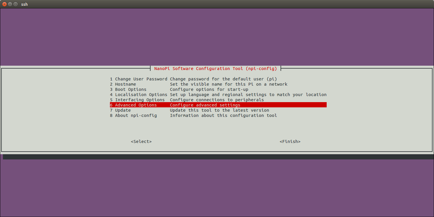
进入SPI菜单:
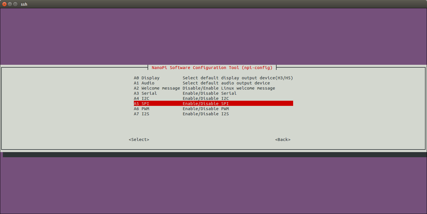
选择是否使能SPI0:
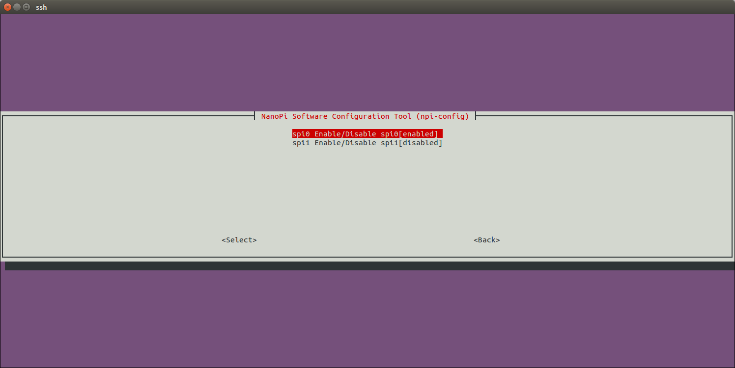
选择enable SPI0后,再选择SPI0上连接的设备为Matrix-2'8_SPI_Key_TFT:
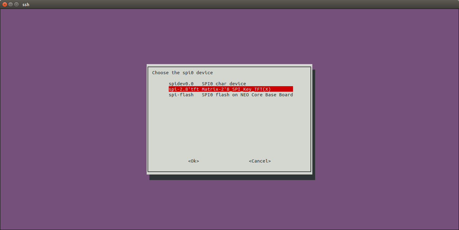
最后返回主菜单,选择<Finish>,然后根据提示重启系统。重新启动系统后,执行下列命令检查Matrix-2'8_SPI_Key_TFT的显示芯片和触摸芯片是否被使能:
$ ls /dev/fb-st7789s
/dev/fb-st7789s
/dev/fb-st7789s就是显示芯片的framebuffer设备节点。
$ ls /dev/input/ts-ads7846
/dev/input/ts-ads7846
/dev/input/ts-ads7846就是触摸芯片的设备节点。
第一次进入系统时会进行触摸校准,根据屏幕的提示点击5个点完成校准即可。
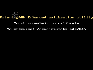
注意:在Linux4.x主线内核中,默认支持的是使用Pin12作为触摸芯片的使能引脚的Matrix-2'8_SPI_Key_TFT-1706版本。
通过npi-config使能Matrix-2'8_SPI_Key_TFT后,系统会将默认的登录显示设备设置为Matrix-2'8_SPI_Key_TFT。如果你想开机运行Qt-demo程序,可以在npi-config中进行如下配置,进入Boot Options菜单:
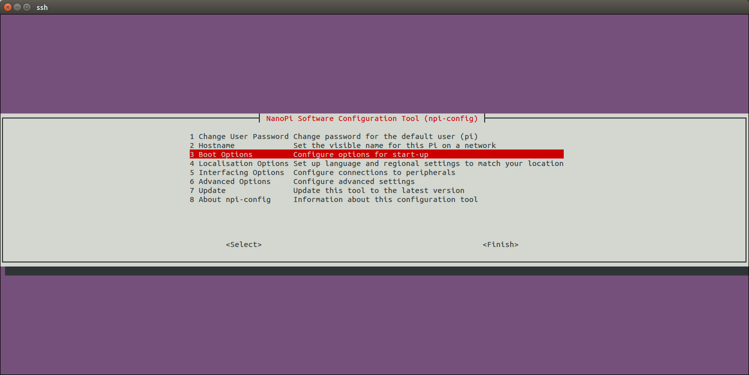
进入Autologin菜单:
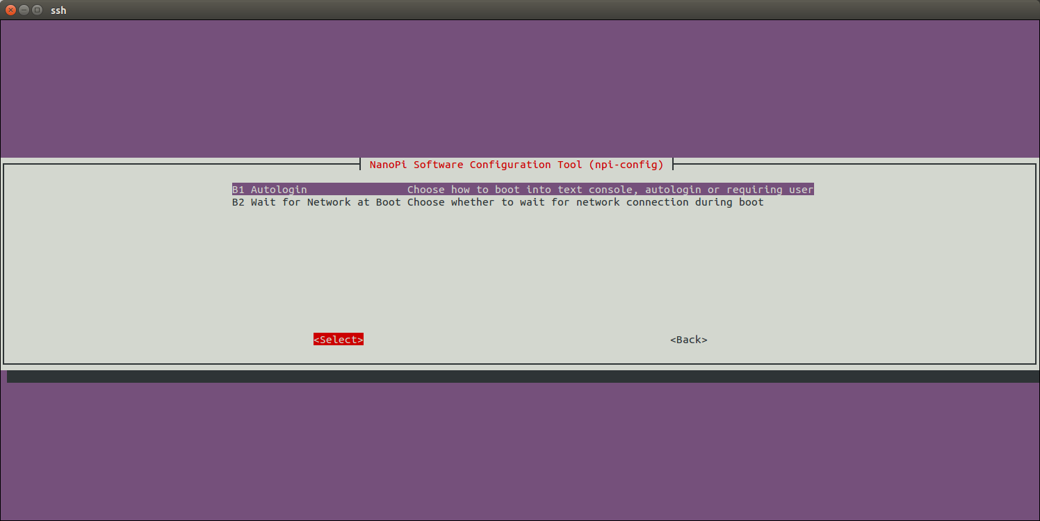
进去Qt/Embedded菜单:
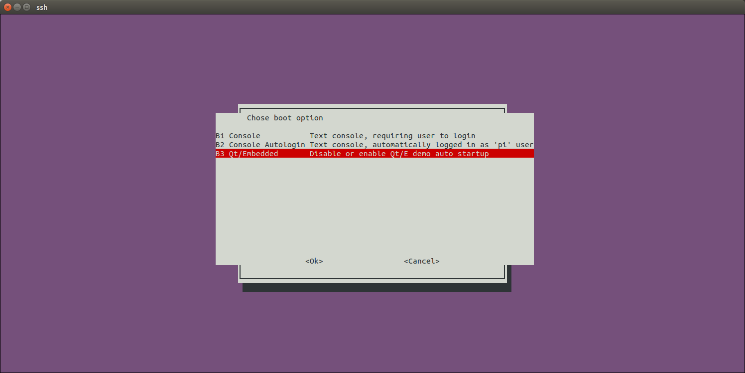
使能Qt/E Demo:
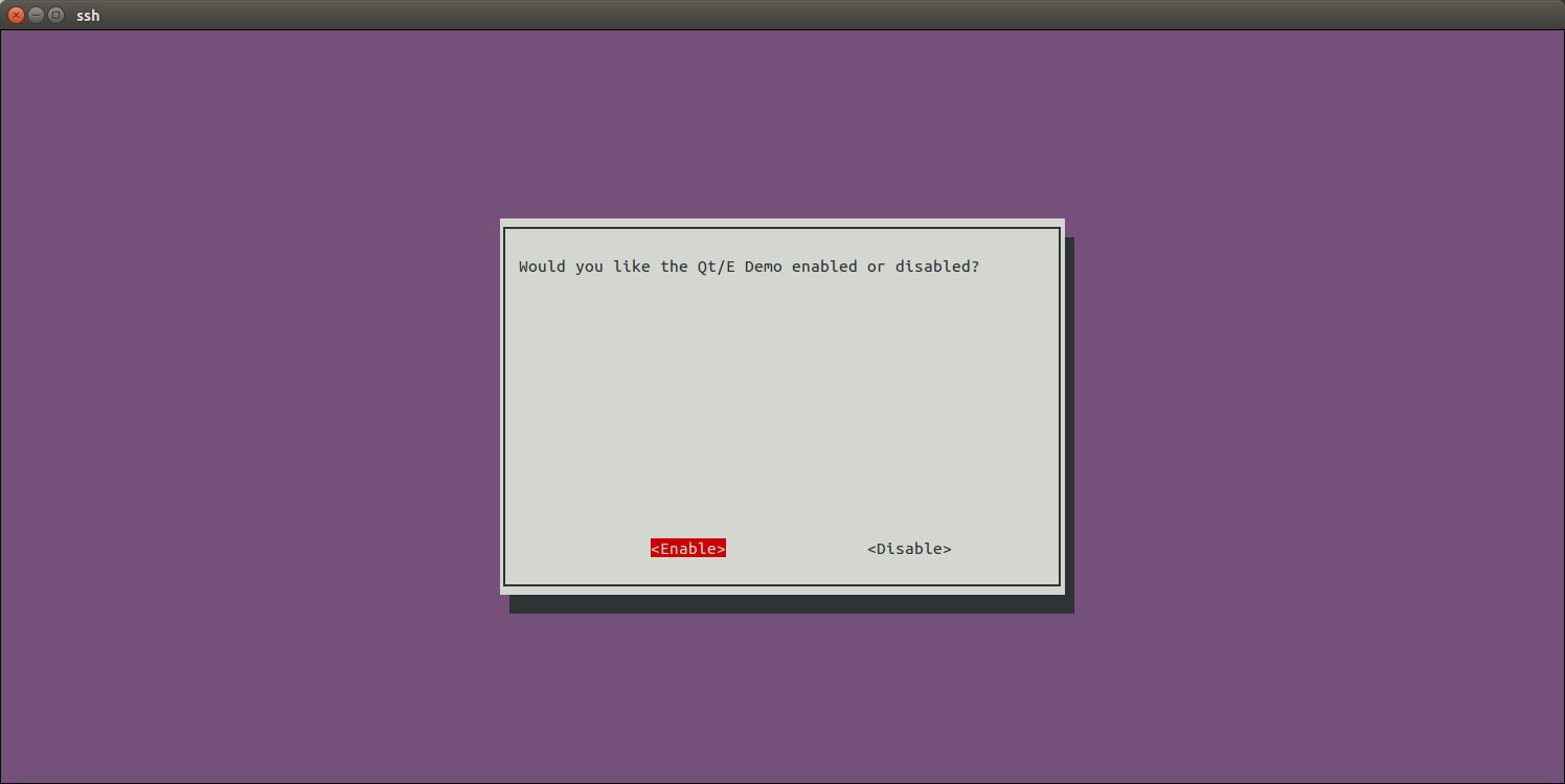
最后返回主菜单,选择<Finish>,然后根据提示重启系统。重新启动系统后,屏幕上会自动运行Qt/E demo,效果如下:
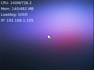
6.1.1.2 控制背光
$ echo 1 >/sys/class/backlight/fb_st7789v/bl_power   # 关闭背光
$ echo 0 >/sys/class/backlight/fb_st7789v/bl_power   # 打开背光
6.1.1.3 对于Matrix-2'8_SPI_Key_TFT-1512的额外设置
对于使用Matrix-2'8_SPI_Key_TFT-1512(丝印T28-02 1512)+ NanoPi M1/NanoPi M1 Plus的用户,需要自行修改内核代码选择使用Pin26作为触摸使能引脚才能正常使用触摸功能。
假设你已经参考H3 主线内核的维基Mainline U-boot & Linux成功克隆并编译了Linux内核,则还需要修改下列代码:
修改下列代码:
$ vi linux/arch/arm/boot/dts/sun8i-h3-nanopi
    ...
    spi0_cs_pins: spi0_cs_pins {
        pins = "PC3", "PA6";
        function = "gpio_out";
    };
    ...
&spi0 {
    ...
    cs-gpios = <&pio 2 3 GPIO_ACTIVE_HIGH>, <&pio 0 6 GPIO_ACTIVE_HIGH>;
    ...
其中<&pio 0 6 GPIO_ACTIVE_HIGH>表示使用GPIOA6(Pin12)作为触摸使能引脚,将其修改为GPIOA17(Pin26):
    ...
    spi0_cs_pins: spi0_cs_pins {
        pins = "PC3", "PA17";
        function = "gpio_out";
    };
    ...
&spi0 {
    ...
    cs-gpios = <&pio 2 3 GPIO_ACTIVE_HIGH>, <&pio 0 17 GPIO_ACTIVE_HIGH>;
    ...
然后重新编译内核,拷贝arch/arm/boot/dts/目录下的sun8i-h3-nanopi-m1.dtb/sun8i-h3-nanopi-m1-plus.dtb到TF卡boot分区下,重新启动板子即可。
6.1.2 Linux 3.4
启动开发板并运行FriendlyCoore系统,进入系统后克隆Matrix代码仓库:
$ apt-get update && apt-get install git
$ git clone https://github.com/friendlyarm/matrix.git
克隆完成后会得到一个名为matrix的目录。
编译并运行Qt测试程序:
cd matrix/demo/nanopi-status
./build.sh
./run.sh /dev/fb-st7789s
nanopi-status是一个简单的Qt程序,可用于显示系统的基本信息,效果如下:
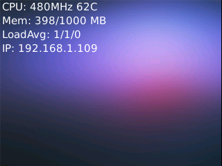
脚本run.sh会先加载tft屏的驱动模块然后运行Qt程序,驱动模块加载成功后会生成设备节点/dev/fb-st7789s,下列命令可以确定驱动模块是否成功加载:
lsmod
Module                  Size  Used by
fbtft_device           29235  0
在确定tft驱动模块已加载的前提下,运行下列命令可以显示三原色:
cd matrix/demo/matrix-lcdtest
make
export LCDSET_FB_DEV=/dev/fb-st7789s
./matrix-lcdtest
三原色可以呈现出屏幕的最佳显示效果。
6.2 S5P4418/S5P6818平台
以下内容仅适用于Linux-4.4内核, 以NanoPi Fire3为例,开机后,在终端上执行以下命令初始化SPI 2.8寸屏,这些操作只需要执行一次:
sudo mount /dev/mmcblk0p1 /boot
sudo apt-get update
sudo apt-get install device-tree-compiler
sudo fdtput /boot/s5p6818-nanopi3-rev05.dtb spi0/spidev@0 status -t s "disabled"
sudo fdtget /boot/s5p6818-nanopi3-rev05.dtb spi0/spidev@0 status
sudo fdtput /boot/s5p6818-nanopi3-rev05.dtb spi0/fbtft@0 status -t s "okay"
sudo fdtget /boot/s5p6818-nanopi3-rev05.dtb spi0/fbtft@0 status
sudo reboot
注意,在上述命令中,s5p6818-nanopi3-rev05.dtb是NanoPi Fire3开发板所用的内核dtb文件,其它开发板型号需要自已查看文件 /sys/devices/platform/board/info 中的信息来确定文件名,输入如下命令:
cat /sys/devices/platform/board/info
在NanoPi Fire3开发板上,info文件的内容如下:
Hardware : NANOPI3
Revision : 0005
Serial : fa6818dba7110739
其中,Hardware字段是NANOPI3,Revision字段是0005,CPU是S5P6818,所以NanoPi Fire3内核dtb文件名为 s5p6818-nanopi3-rev05.dtb。
配置完dtb文件,重启开发板后,可以用lsmod命令检查下是否加载了fb_st7789v模块:
lsmod正常会输出如下内容:
Module Size Used by
fb_st7789v 3315 0
fbtft 31881 1 fb_st7789v
以及用dmesg命令可以查看到SPI屏已经被初始化为fb1设备:
dmesg | grep fb_st7789v
正常会输出如下内容:
[ 6.728000] fb_st7789v: module is from the staging directory, the quality is unknown, you have been warned.
[ 6.908000] graphics fb1: fb_st7789v frame buffer, 320x240, 150 KiB video memory, 4 KiB buffer memory, fps=35, spi0.0 at 50 MHz
接下来要做的事情就比较简单了,无论是运行Qt,还是X-Windows,只需要正确设置Framebuffer设备为fb1即可。
6.2.1 在2.8寸屏上运行Lubuntu桌面
在 lubuntu desktop系统里执行以下操作:
首先删除armsoc的配置文件:
sudo rm -f /usr/share/X11/xorg.conf.d/20-armsoc.conf
然后新建一个配置文件 /etc/X11/xorg.conf:
sudo vi /etc/X11/xorg.conf
内容如下:
Section "Monitor"
    Identifier          "Primary"
    VendorName          "FriendlyARM"
EndSection

Section "Device"
    Identifier          "Primary"
    Driver              "fbdev"
    Option              "fbdev" "/dev/fb1"
EndSection
重启后可以看到图像:
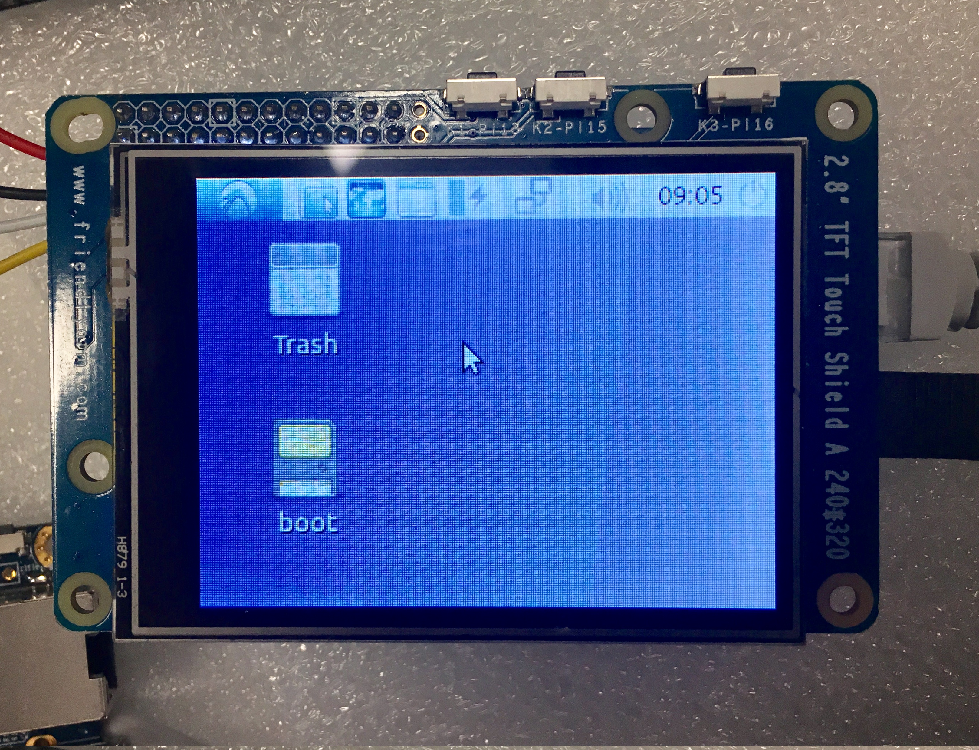
目前暂时不支持触摸屏,可使用鼠标和键盘操作。
6.2.2 在2.8寸屏上运行Qt程序
在friendly-core系统终端里执行以下命令,运行一个Qt示例:
. setqt5env
export QT_QPA_PLATFORM=linuxfb:fb=/dev/fb1
export QT_QPA_EGLFS_TSLIB=1
export QT_QPA_GENERIC_PLUGINS=tslib,evdevkeyboard
$QTDIR/examples/widgets/widgets/tetrix/tetrix
Qt示例画面如下所示:
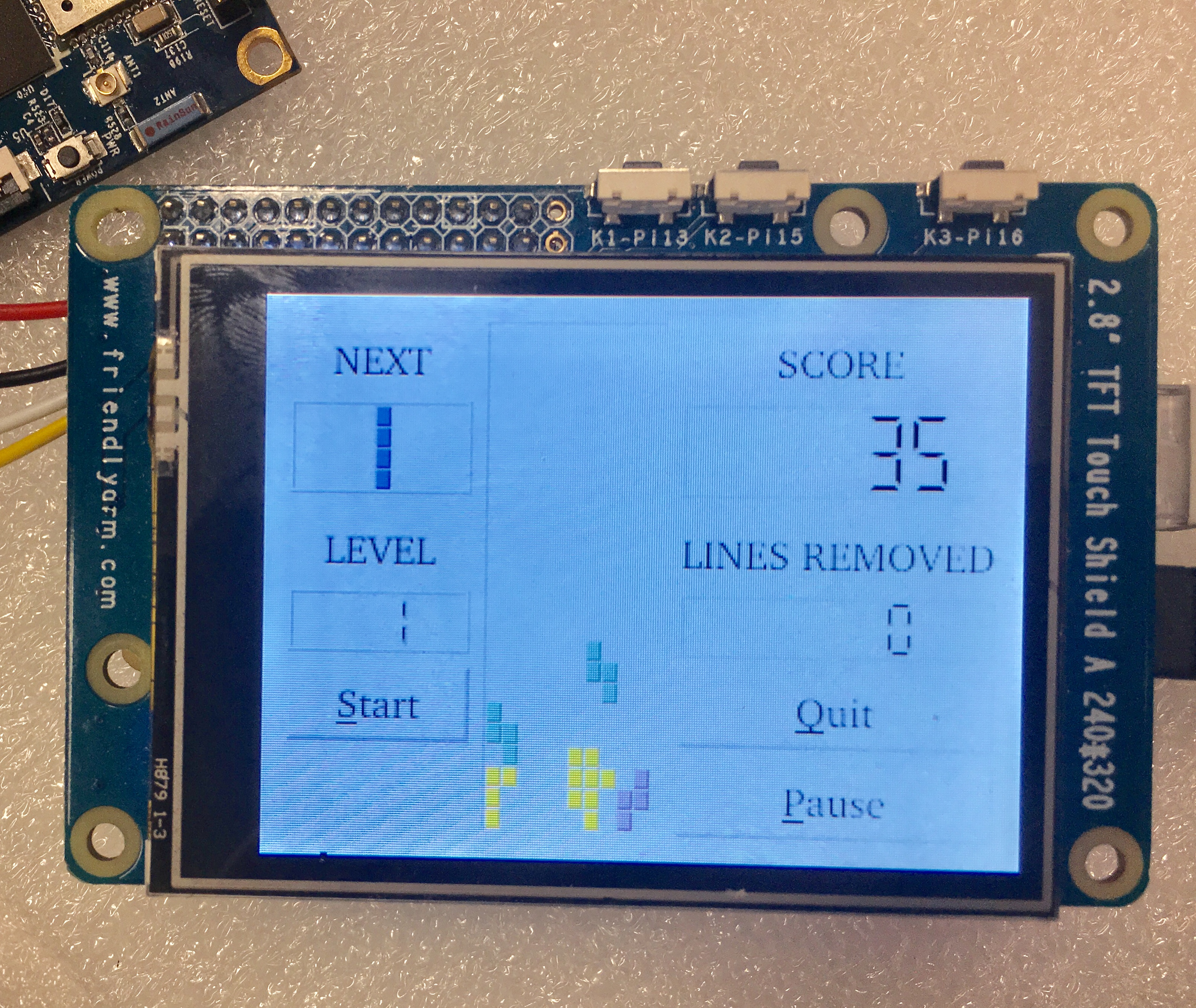
目前暂时不支持触摸屏,可使用鼠标和键盘操作。
7 相关资料
- [Schematic](Matrix - 2'8 SPI Key TFT-Schematic.pdf)
