Difference between revisions of "Matrix - I2C LCD1602"
(→Update Log) |
|||
| (25 intermediate revisions by 3 users not shown) | |||
| Line 5: | Line 5: | ||
[[File:LCD160202.png|thumb|I2C LCD1602]] | [[File:LCD160202.png|thumb|I2C LCD1602]] | ||
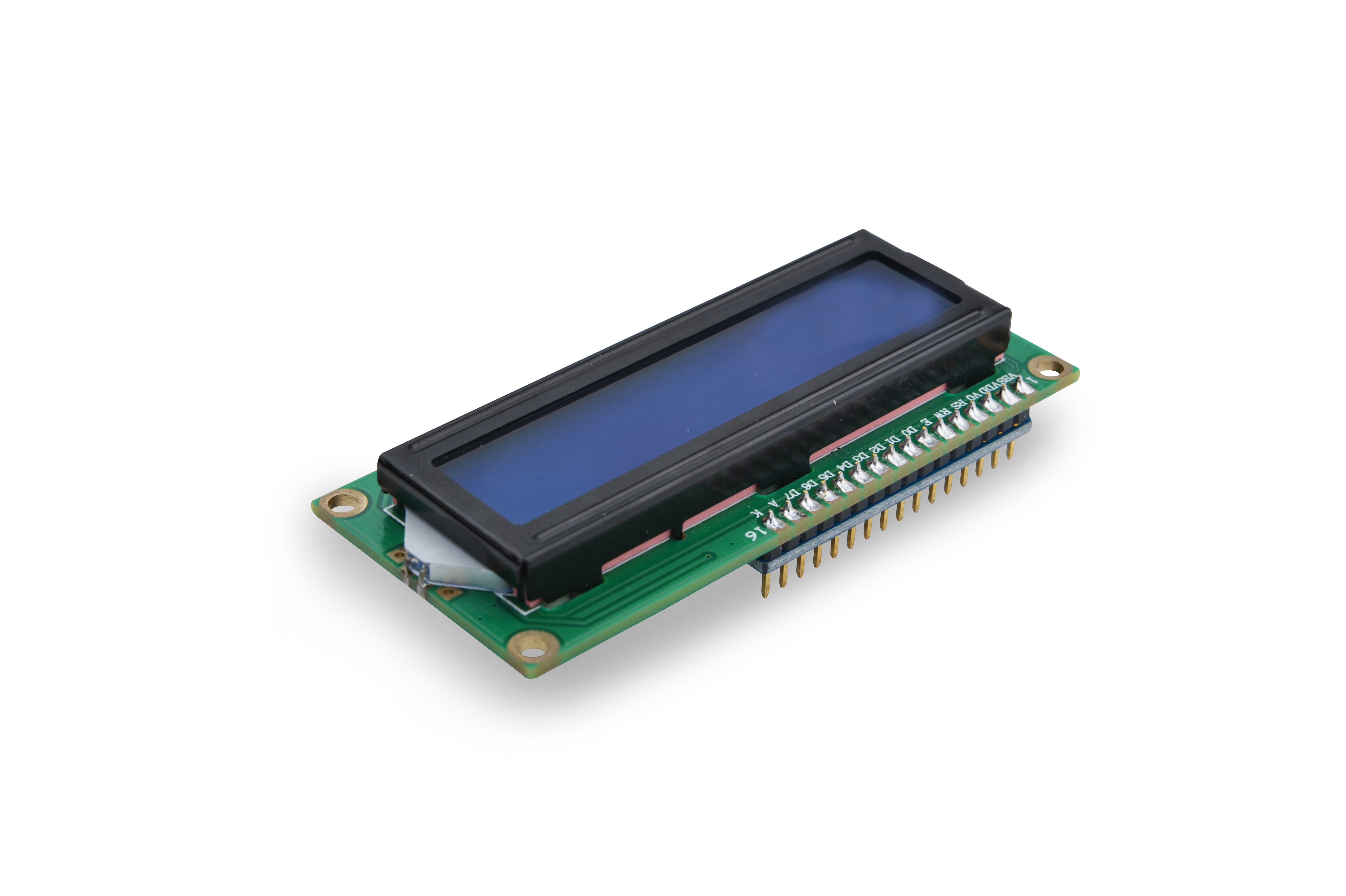
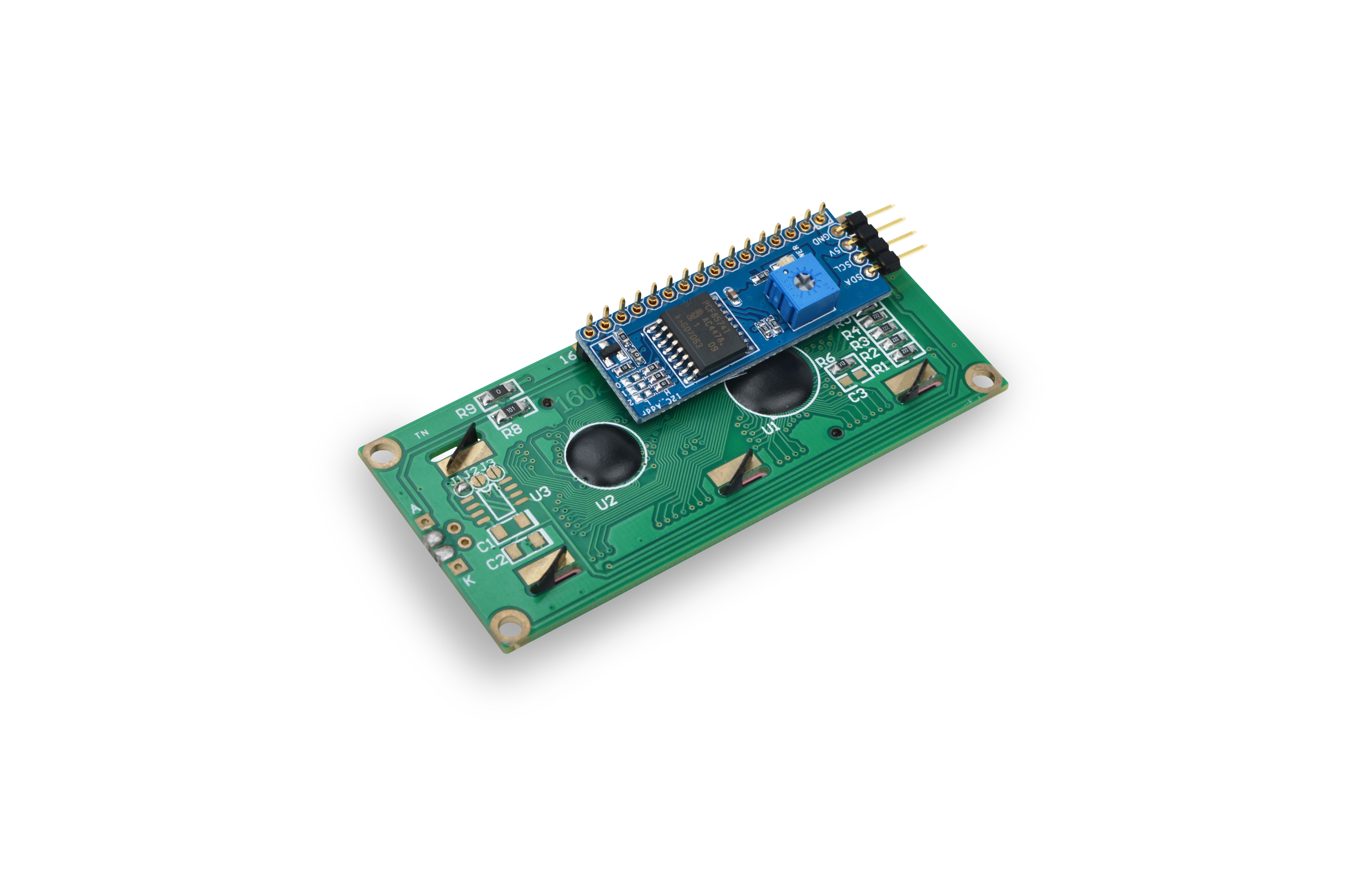
* The Matrix-I2C_LCD1602 is an LCD display module composed of an LCD1602 and a PCF8574 module.<br> | * The Matrix-I2C_LCD1602 is an LCD display module composed of an LCD1602 and a PCF8574 module.<br> | ||
| − | * | + | * The LCD1602 can display up to 16x2 characters. It has a parallel interface.<br> |
| − | * | + | * The PCF8574 provides GPIO expansion up to 8 bit for I2C. It communicates with a master via I2C and converts data from the master to parallel signals to the LCD1602 thus controls the LCD's display and back light. |
| − | == | + | ==Features== |
| − | * | + | * I2C interface, LCD display and backlight control |
| − | * 2. | + | * 2.54mm spacing pin |
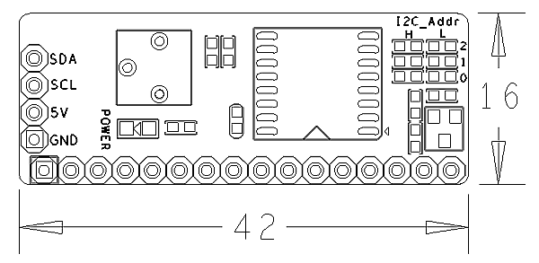
| − | * | + | * IIC Module PCB dimension(mm): 16 x 42 |
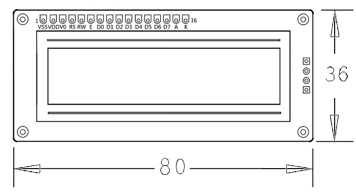
| − | * LCD1602 | + | * LCD1602 PCB dimension (mm): 36 x 80 |
| − | [[File:lpdpcb.png|frameless|400px| | + | [[File:lpdpcb.png|frameless|400px|IIC Module PCB]] |
[[File:lcdpcb.png|frameless|400px|LCD1602 PCB]] | [[File:lcdpcb.png|frameless|400px|LCD1602 PCB]] | ||
| − | * | + | * Pin Description: |
{| class="wikitable" | {| class="wikitable" | ||
|- | |- | ||
| − | | | + | |Pin || Description |
|- | |- | ||
|SDA || I2C SDA | |SDA || I2C SDA | ||
| Line 25: | Line 25: | ||
|SCL || I2C SCL | |SCL || I2C SCL | ||
|- | |- | ||
| − | |5V || | + | |5V || Supply Voltage 5V |
|- | |- | ||
| − | |GND || | + | |GND || Ground |
|} | |} | ||
| − | == | + | ==Basic Device Operation== |
| − | === | + | ===PCF8574=== |
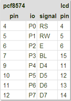
| − | * | + | * The PCF8574 has I2C parallel expansion. It has an 8bit (P0 - P7) I2C interface. |
| − | * | + | * The PCF8574 communicates with a master via I2C. The PCF8574's chip model is PCF8574T whose address specification is as follows: |
[[File:pcf8574.png|frameless|400px|PCF8574]] | [[File:pcf8574.png|frameless|400px|PCF8574]] | ||
| − | * | + | * If A2 - A0 are all set to 1 the 7bit address will be 0x27(0100111). By default RW is 0 and it is in the write mode. |
| − | * | + | * In the write mode after opening the i2c-0 device and setting up its address the master can write data to it. |
| − | * | + | * If you need to read data from it you will need to set the module to the read mode (RW set to 1). Please refer to the PCF8574's datasheet for more details. |
| − | === | + | ===LCD1602=== |
| − | * | + | * The connection diagram between the PCF8574 module and the LCD module is as follows: |
[[File:1602.png|frameless|400px|1602]] | [[File:1602.png|frameless|400px|1602]] | ||
| − | * | + | * RS is instruction/data register selection. RW is read/write selection. E is enable signal(edge triggering). BL is back light control. D4-D7 are data bits. |
| − | * | + | * The LCD module is controlled by four data bits through which we can send instructions to control its state. Because it has eight instruction/data bits (DB7 - DB0) when writing each instruction/data we need to write the most significant four bits DB7 - DB4 first and then the least significant four bits DB3 - DB0. |
| − | * | + | * Note: the LCD module has 192 most commonly used characters stored in CGROM. When we write a common character e.g "A" it will directly display "A". In addition it can store up to eight user defined characters in RAM called CGRAM. |
| − | == | + | ==Applications== |
| − | + | ===Connect to NanoPi M1=== | |
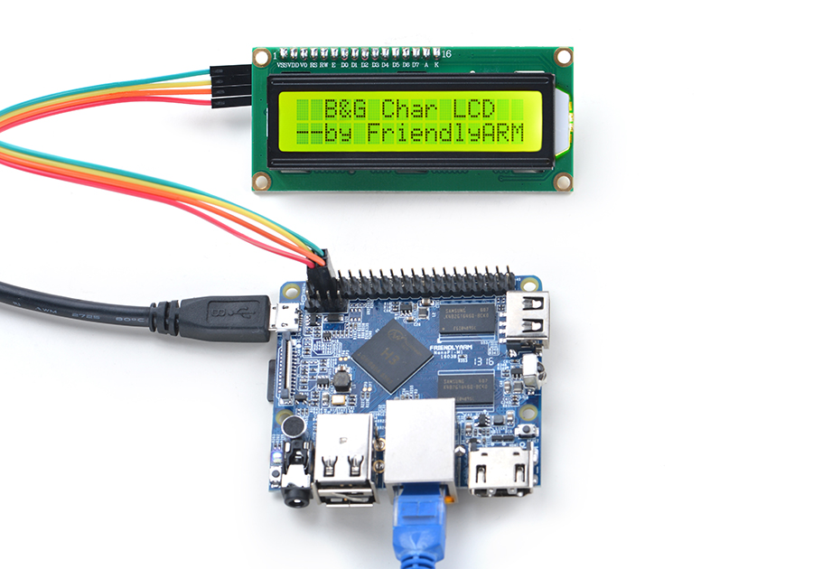
| − | + | Refer to the following connection diagram to connect the module to the NanoPi M1:<br> | |
| − | + | [[File:Matrix-I2C_LCD1602_nanopi_m1.jpg|frameless|600px|Matrix-I2C_LCD1602_nanopi_m1]] | |
| − | + | ||
| − | + | ||
| − | + | Connection Details | |
| + | {| class="wikitable" | ||
| + | |- | ||
| + | |Matrix-I2C_LCD1602 || NanoPi M1 | ||
| + | |- | ||
| + | |SDA || Pin3 | ||
| + | |- | ||
| + | |SCL || Pin5 | ||
| + | |- | ||
| + | |5V || Pin4 | ||
| + | |- | ||
| + | |GND || Pin6 | ||
| + | |} | ||
| + | |||
| + | ===Connect to NanoPi 2=== | ||
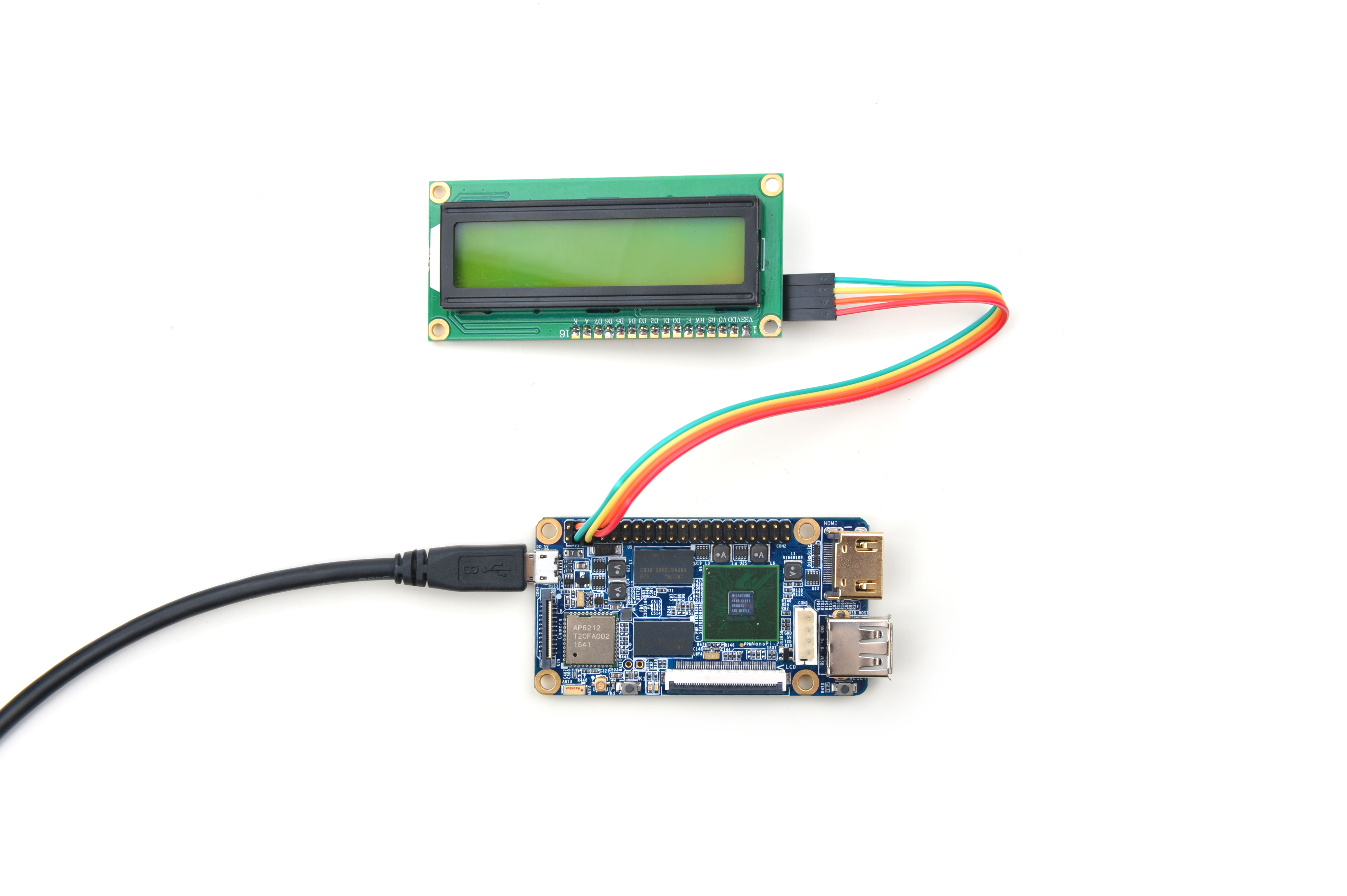
| + | Refer to the following connection diagram to connect the module to the NanoPi 2:<br> | ||
| + | [[File:Matrix-I2C_LCD1602_nanopi_2.jpg|frameless|600px|Matrix-I2C_LCD1602_nanopi_2]] | ||
| + | |||
| + | Connection Details: | ||
| + | {| class="wikitable" | ||
| + | |- | ||
| + | |Matrix-I2C_LCD1602 || NanoPi 2 | ||
| + | |- | ||
| + | |SDA || Pin3 | ||
| + | |- | ||
| + | |SCL || Pin5 | ||
| + | |- | ||
| + | |5V || Pin4 | ||
| + | |- | ||
| + | |GND || Pin6 | ||
| + | |} | ||
| + | |||
| + | ===Connect to NanoPi M2 / NanoPi 2 Fire=== | ||
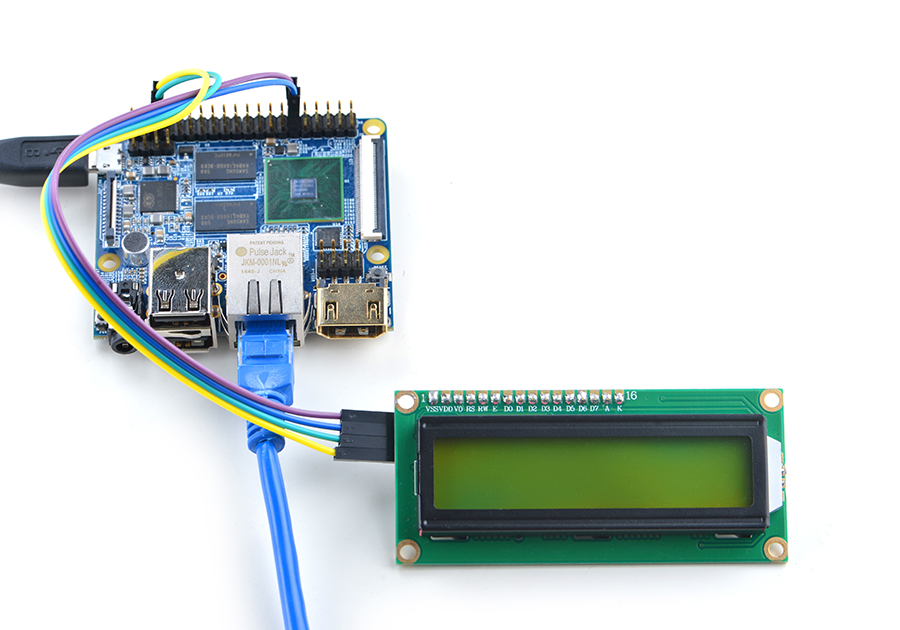
| + | Refer to the following connection diagram to connect the module to the NanoPi M2/ NanoPi 2 Fire.<br> | ||
| + | [[File:Matrix-I2C_LCD1602_nanopi_m2.jpg|frameless|600px|Matrix-I2C_LCD1602_nanopi_m2]] | ||
| + | |||
| + | Connection Details: | ||
| + | {| class="wikitable" | ||
| + | |- | ||
| + | |Matrix-I2C_LCD1602 || NanoPi M2 | ||
| + | |- | ||
| + | |SDA || Pin3 | ||
| + | |- | ||
| + | |SCL || Pin5 | ||
| + | |- | ||
| + | |5V || Pin4 | ||
| + | |- | ||
| + | |GND || Pin6 | ||
| + | |} | ||
| + | |||
| + | ===Connect to NanoPC-T2=== | ||
| + | Refer to the following connection diagram to connect the module to the NanoPC-T2:<br> | ||
| + | [[File:Matrix-I2C_LCD1602_NanoPC-T2.jpg|frameless|600px|Matrix-I2C_LCD1602_NanoPC-T2]] | ||
| + | |||
| + | Connection Details: | ||
| + | {| class="wikitable" | ||
| + | |- | ||
| + | |Matrix-I2C_LCD1602 || NanoPC-T2 | ||
| + | |- | ||
| + | |SDA || Pin6 | ||
| + | |- | ||
| + | |SCL || Pin5 | ||
| + | |- | ||
| + | |5V || Pin29 | ||
| + | |- | ||
| + | |GND || Pin30 | ||
| + | |} | ||
| + | |||
| + | ==Compile & Run Test Program== | ||
| + | Boot your ARM board with Debian and copy the matrix code: | ||
| + | <syntaxhighlight lang="bash"> | ||
| + | $ apt-get update && apt-get install git | ||
| + | $ git clone https://github.com/friendlyarm/matrix.git | ||
| + | </syntaxhighlight> | ||
| + | If your cloning is done successfully a "matrix" directory will be generated. | ||
| + | |||
| + | Compile and install Matrix: | ||
| + | <syntaxhighlight lang="bash"> | ||
| + | $ cd matrix | ||
| + | $ make && make install | ||
| + | </syntaxhighlight> | ||
| + | |||
| + | Run test program: | ||
| + | <syntaxhighlight lang="bash"> | ||
| + | $ matrix-lcd1602 | ||
| + | </syntaxhighlight> | ||
| + | Note: this module is not plug and play therefore before running the module please make sure it is connected to an ARM board.<br> | ||
| + | Here is what you should observe:<br> | ||
| + | [[File:matrix-lcd1602_result.png|frameless|600px|matrix-lcd1602_result]] <br> | ||
| + | The LCD will show the following two lines:<br> | ||
| + | " B&G Char LCD" <br> | ||
| + | "--by FriendlyARM" <br> | ||
| + | If the LCD doesn't show them clearly you can adjust the resistor to highlight the characters. | ||
| + | |||
| + | ==Code Sample== | ||
| + | This Matrix code sample can work with all the ARM boards mentioned in this module's wiki. The name of this code sample is "matrix-i2c_lcd1602". Here is its source code: | ||
| + | <syntaxhighlight lang="c"> | ||
| + | int main(int argc, char ** argv) | ||
| + | { | ||
| + | int devFD, board; | ||
| + | int i2cDev = 0; | ||
| + | |||
| + | if ((board = boardInit()) < 0) { | ||
| + | printf("Fail to init board\n"); | ||
| + | return -1; | ||
| + | } | ||
| + | |||
| + | if (argc == 2) | ||
| + | i2cDev = atoi(argv[1]); | ||
| + | if ((devFD = LCD1602Init(i2cDev)) == -1) { | ||
| + | printf("Fail to init LCD1602\n"); | ||
| + | return -1; | ||
| + | } | ||
| + | if (LCD1602Clear(devFD) == -1) { | ||
| + | printf("Fail to Clear\n"); | ||
| + | } | ||
| + | printf("clearing LCD1602\n"); | ||
| + | sleep(1); | ||
| + | if (LCD1602DispLines(devFD, " B&G Char LCD", "--by FriendlyARM") == -1) { | ||
| + | printf("Fail to Display String\n"); | ||
| + | } | ||
| + | printf("displaying LCD1602\n"); | ||
| + | LCD1602DeInit(devFD); | ||
| + | return 0; | ||
| + | } | ||
| + | </syntaxhighlight> | ||
| + | For more details about this APIs called in this code sample refer to [[Matrix API reference manual]] <br> | ||
| + | |||
| + | ==Connect to Arduino Board== | ||
| + | ===Preparations=== | ||
| + | Make sure your Arduino board can work. Here is a reference link - https://www.arduino.cc/en/Guide/HomePage <br> | ||
| + | Here we tried the Arduino Uno. | ||
| + | |||
| + | ===Hardware Connection=== | ||
| + | Refer to the following diagram to connect the Matrix-I2C_LCD1602 to an Arduino Uno<br> | ||
| + | [[File:matrix-i2c_lcd1602_arduino.jpg|frameless|600px|matrix-i2c_lcd1602_arduino]] | ||
| + | |||
| + | ===Compile & Run Test Program=== | ||
| + | All the matrix modules' code samples for Arduino are maintained on GitHub - https://github.com/friendlyarm/matrix-arduino.git <br> | ||
| + | Clone the matrix code from GitHub | ||
| + | <syntaxhighlight lang="bash"> | ||
| + | $ git clone git://github.com/friendlyarm/matrix-arduino.git | ||
| + | </syntaxhighlight> | ||
| + | If this is successful a "matrix-arduino" directory will be generated, which will contain all the matrix modules' code samples. | ||
| + | |||
| + | Copy the entire directory "matrix-i2c_lcd1602" to "Arduino_IDE/libraries" | ||
| + | <syntaxhighlight lang="bash"> | ||
| + | $ cd matrix-arduino | ||
| + | $ cp matrix-i2c_lcd1602 Arduino_IDE/libraies -r | ||
| + | </syntaxhighlight> | ||
| + | |||
| + | Start Arduino IDE <br> | ||
| + | Click on File->Examples->matrix-i2c_lcd1602->displaychar and run the test program.<br> | ||
| + | Click on upload and run the test program.<br> | ||
| + | |||
| + | ===Code Sample=== | ||
| + | <syntaxhighlight lang="c"> | ||
| + | #include <Wire.h> | ||
| + | #include <LiquidCrystal_I2C.h> | ||
| + | |||
| + | // set the LCD address to 0x27 for a 16 chars and 2 line display | ||
| + | LiquidCrystal_I2C lcd(0x27,16,2); | ||
| + | |||
| + | void setup() | ||
| + | { | ||
| + | lcd.init(); | ||
| + | lcd.backlight(); | ||
| + | lcd.setCursor(2, 0); | ||
| + | lcd.print("B&G Char LCD"); | ||
| + | lcd.setCursor(0, 1); | ||
| + | lcd.println("--by FriendlyARM"); | ||
| + | } | ||
| + | |||
| + | void loop() | ||
| + | { | ||
| + | } | ||
| + | </syntaxhighlight> | ||
| + | |||
| + | <!--- | ||
| + | ==Download Matrix Source Code== | ||
| + | All the matrix modules' code samples are open source. They are maintained on GitHub - https://github.com/friendlyarm/matrix.git <br> | ||
| + | Each branch in this hub contains the matrix modules' code samples for a board that the matrix modules can work with.<br> | ||
| + | * The nanopi branch contains the matrix modules' code samples for the NanoPi | ||
| + | * The nanopi 2 branch contains the matrix modules' code samples for the NanoPi 2 | ||
| + | * The tiny4412 branch contains the matrix modules' code samples for the Tiny4412 | ||
| + | * The raspberrypi branch contains the matrix modules' code samples for the RaspberryPi | ||
| + | |||
| + | Install the git utility on a PC running Ubuntu14.04 | ||
<syntaxhighlight lang="bash"> | <syntaxhighlight lang="bash"> | ||
$ sudo apt-get install git | $ sudo apt-get install git | ||
</syntaxhighlight> | </syntaxhighlight> | ||
| − | + | Clone the matrix code from GitHub | |
<syntaxhighlight lang="bash"> | <syntaxhighlight lang="bash"> | ||
| − | $ git clone | + | $ git clone https://github.com/friendlyarm/matrix.git |
</syntaxhighlight> | </syntaxhighlight> | ||
| − | + | If this is successful a "matrix" directory will be generated, which will contain all the matrix modules' code samples. | |
| − | == | + | ==Connect to NanoPi 2== |
| − | === | + | ===Hardware Connection=== |
| − | + | Please refer to the following connection diagram to connect the Matrix-I2C_LCD1602 to the NanoPi 2:<br> | |
| − | + | [[File:Matrix-I2C_LCD1602_nanopi_2.jpg|frameless|600px|Matrix-I2C_LCD1602_nanopi_2]] | |
| − | + | ||
| + | Connection Details: | ||
| + | {| class="wikitable" | ||
| + | |- | ||
| + | |Matrix-I2C_LCD1602 || NanoPi | ||
| + | |- | ||
| + | |SDA || Pin3 | ||
| + | |- | ||
| + | |SCL || Pin5 | ||
| + | |- | ||
| + | |5V || Pin4 | ||
| + | |- | ||
| + | |GND || Pin6 | ||
| + | |} | ||
| + | |||
| + | ===Compile Test Program=== | ||
| + | Please login the matrix hub and enter the nanopi2 branch | ||
| + | <syntaxhighlight lang="bash"> | ||
| + | $ cd matrix | ||
| + | $ git checkout nanopi2 | ||
| + | </syntaxhighlight> | ||
| + | |||
| + | Compile the matrix code | ||
| + | <syntaxhighlight lang="bash"> | ||
| + | $ make CROSS_COMPILE=arm-linux- clean | ||
| + | $ make CROSS_COMPILE=arm-linux- | ||
| + | $ make CROSS_COMPILE=arm-linux- install | ||
| + | </syntaxhighlight> | ||
| + | Note: please make sure to install the cross compiler "arm-linux-gcc-4.9.3" on your PC, which is used to compile files for the NanoPi 2.<br> | ||
| + | Generated library files are under the "install/lib" directory. The test program is under the "install/usr/bin" directory.<br> | ||
| + | The modules are under the "modules" directory. The driver's source code is in github: https://github.com/friendlyarm/linux-3.4.y.git <br> | ||
| + | |||
| + | ===Run Test Program=== | ||
| + | Please insert a TF card which is flashed with Debian to a Linux host and mount its boot and rootfs sections.<br> | ||
| + | We assume the rootfs is mounted to /media/rootfs then please run the following commands to copy the module, library and test program to the card.<br> | ||
| + | <syntaxhighlight lang="bash"> | ||
| + | $ cp modules /media/rootfs/ -r | ||
| + | $ cp install/lib/* /media/rootfs/lib/ -d | ||
| + | $ cp install/usr/bin/* /media/rootfs/usr/bin/ | ||
| + | </syntaxhighlight> | ||
| + | |||
| + | Insert this TF card to your NanoPi 2, power on and run the following command to test.<br> | ||
| + | <syntaxhighlight lang="bash"> | ||
| + | $ matrix-lcd1602 | ||
| + | </syntaxhighlight> | ||
| + | Note: this module is not plug and play therefore before running the module please make sure it is connected to a NanoPi 2.<br> | ||
| + | Here is what you should expect:<br> | ||
| + | [[File:matrix-lcd1602_result.png|frameless|600px|matrix-lcd1602_result]] <br> | ||
| + | The LCD shows the following two lines:<br> | ||
| + | " B&G Char LCD" <br> | ||
| + | "--by FriendlyARM" | ||
| + | |||
| + | ===Code Sample=== | ||
| + | <syntaxhighlight lang="c"> | ||
| + | int main(int argc, char ** argv) | ||
| + | { | ||
| + | int devFD; | ||
| + | if ((devFD = LCD1602Init()) == -1) { | ||
| + | printf("Fail to init LCD1602\n"); | ||
| + | return -1; | ||
| + | } | ||
| + | |||
| + | if (LCD1602Clear(devFD) == -1) { | ||
| + | printf("Fail to Clear\n"); | ||
| + | return -1; | ||
| + | } | ||
| + | printf("clearing LCD1602\n"); | ||
| + | sleep(1); | ||
| + | |||
| + | if (LCD1602DispLines(devFD, " B&G Char LCD", "--by FriendlyARM") == -1) { | ||
| + | printf("Fail to Display String\n"); | ||
| + | return -1; | ||
| + | } | ||
| + | printf("displaying LCD1602\n"); | ||
| + | LCD1602DeInit(devFD); | ||
| + | return 0; | ||
| + | } | ||
| + | </syntaxhighlight> | ||
| + | |||
| + | |||
| + | ==Connect to NanoPi== | ||
| + | ===Preparations=== | ||
| + | Please install a Debian on a NanoPi and an appropriate cross compiler on a PC. Please refer to wiki:[[NanoPi/zh|NanoPi]] <br> | ||
| + | Compile a NanoPi kernel. Note: please use the kernel's source code from the nanopi-v4.1.y-matrix branch.<br> | ||
<syntaxhighlight lang="bash"> | <syntaxhighlight lang="bash"> | ||
$ git clone https://github.com/friendlyarm/linux-4.x.y.git | $ git clone https://github.com/friendlyarm/linux-4.x.y.git | ||
| Line 78: | Line 346: | ||
</syntaxhighlight> | </syntaxhighlight> | ||
| − | === | + | ===Hardware Connection=== |
| − | + | ||
| + | Please refer to the following connection diagram to connect the Matrix-I2C_LCD1602 to the NanoPi <br> | ||
[[File:matrix-i2c_lcd1602_nanopi.jpg|frameless|600px|matrix-i2c_lcd1602_nanopi]] | [[File:matrix-i2c_lcd1602_nanopi.jpg|frameless|600px|matrix-i2c_lcd1602_nanopi]] | ||
| − | + | Connection Details: | |
{| class="wikitable" | {| class="wikitable" | ||
|- | |- | ||
| Line 96: | Line 365: | ||
|} | |} | ||
| − | === | + | ===Compile Test Program=== |
| − | + | Please login the matrix hub and enter the nanopi branch | |
<syntaxhighlight lang="bash"> | <syntaxhighlight lang="bash"> | ||
$ cd matrix | $ cd matrix | ||
| Line 103: | Line 372: | ||
</syntaxhighlight> | </syntaxhighlight> | ||
| − | + | Compile the matrix code | |
<syntaxhighlight lang="bash"> | <syntaxhighlight lang="bash"> | ||
$ make CROSS_COMPILE=arm-linux- clean | $ make CROSS_COMPILE=arm-linux- clean | ||
| Line 109: | Line 378: | ||
$ make CROSS_COMPILE=arm-linux- install | $ make CROSS_COMPILE=arm-linux- install | ||
</syntaxhighlight> | </syntaxhighlight> | ||
| − | + | Note: please make sure to install the cross compiler "arm-linux-gcc-4.4.3" on your PC, which is used to compile files for the NanoPi-Debian.<br> | |
| − | + | Generated library files are under the "install/lib" directory. Applications are under the "install/usr/bin" directory. The test program for the "Matrix-I2C_LCD1602" module is "matrix-lcd1602".<br> | |
| − | === | + | ===Run Test Program=== |
| − | + | Please copy the library files and test program to the NanoPi | |
<syntaxhighlight lang="bash"> | <syntaxhighlight lang="bash"> | ||
$ cp install/usr/bin/* nanopi_rootfs/usr/bin/ | $ cp install/usr/bin/* nanopi_rootfs/usr/bin/ | ||
| Line 119: | Line 388: | ||
</syntaxhighlight> | </syntaxhighlight> | ||
| − | + | Power on the NanoPi and run the following command in Debian's terminal <br> | |
| − | + | Note: this module is not plug and play therefore before running the module please make sure it is connected to a NanoPi. | |
<syntaxhighlight lang="bash"> | <syntaxhighlight lang="bash"> | ||
$ matrix-lcd1602 | $ matrix-lcd1602 | ||
</syntaxhighlight> | </syntaxhighlight> | ||
| − | === | + | ===Code Sample=== |
<syntaxhighlight lang="c"> | <syntaxhighlight lang="c"> | ||
int main(int argc, char ** argv) | int main(int argc, char ** argv) | ||
| Line 152: | Line 421: | ||
</syntaxhighlight> | </syntaxhighlight> | ||
| − | == | + | ==Connect to Tiny4412== |
| − | === | + | ===Preparations=== |
| − | + | Please refer to the Tiny4412's user's manual to install a UbuntuCore on the Tiny4412 and install an appropriate cross compiler on a PC.<br> | |
| − | + | Note: only the Tiny4412SDK-1506 carrier board can work with this module. | |
| − | === | + | ===Hardware Connection=== |
| − | + | Please refer to the following diagram to connect the Matrix-I2C_LCD1602 to the Tiny4412 <br> | |
[[File:matrix-i2c_lcd1602_tiny4412.jpg|frameless|600px|matrix-i2c_lcd1602_tiny4412]] | [[File:matrix-i2c_lcd1602_tiny4412.jpg|frameless|600px|matrix-i2c_lcd1602_tiny4412]] | ||
| − | + | Connection Details: | |
{| class="wikitable" | {| class="wikitable" | ||
|- | |- | ||
| Line 175: | Line 444: | ||
|} | |} | ||
| − | === | + | ===Compile Test Program=== |
| − | + | Please login the Matrix hub and enter the matrix-tiny4412 branch | |
<syntaxhighlight lang="bash"> | <syntaxhighlight lang="bash"> | ||
$ cd matrix | $ cd matrix | ||
| Line 182: | Line 451: | ||
</syntaxhighlight> | </syntaxhighlight> | ||
| − | + | Compile the Matrix code | |
<syntaxhighlight lang="bash"> | <syntaxhighlight lang="bash"> | ||
$ make CROSS_COMPILE=arm-linux-gnueabihf- clean | $ make CROSS_COMPILE=arm-linux-gnueabihf- clean | ||
| Line 188: | Line 457: | ||
$ make CROSS_COMPILE=arm-linux-gnueabihf- install | $ make CROSS_COMPILE=arm-linux-gnueabihf- install | ||
</syntaxhighlight> | </syntaxhighlight> | ||
| − | + | Note: please make sure to install the cross compiler "arm-linux-gnueabihf-gcc-4.7.3" on your PC, which is used to compile files for the Tiny4412-UbuntuCore.<br> | |
| − | + | Generated library files are under the "install/lib" directory. Applications are under the "install/usr/bin" directory. The test program for the "Matrix-I2C_LCD1602" module is "matrix-lcd1602". | |
| − | === | + | ===Run Test Program=== |
| − | + | Please copy the library files and test program to the Tiny4412 | |
<syntaxhighlight lang="bash"> | <syntaxhighlight lang="bash"> | ||
$ cp install/usr/bin/* tiny4412_rootfs/usr/bin/ | $ cp install/usr/bin/* tiny4412_rootfs/usr/bin/ | ||
| Line 198: | Line 467: | ||
</syntaxhighlight> | </syntaxhighlight> | ||
| − | + | Power on the Tiny4412 and run the following command in UbuntuCore's terminal <br> | |
| − | + | Note: this module is not plug and play therefore before running the module please make sure it is connected to a Tiny4412. | |
<syntaxhighlight lang="bash"> | <syntaxhighlight lang="bash"> | ||
$ matrix-lcd1602 | $ matrix-lcd1602 | ||
</syntaxhighlight> | </syntaxhighlight> | ||
| − | === | + | ===Code Sample=== |
<syntaxhighlight lang="c"> | <syntaxhighlight lang="c"> | ||
int main(int argc, char ** argv) | int main(int argc, char ** argv) | ||
| Line 231: | Line 500: | ||
</syntaxhighlight> | </syntaxhighlight> | ||
| − | == | + | ==Connect to RaspberryPi== |
| − | == | + | ==Connect to Arduino== |
| − | === | + | ===Preparations=== |
| − | + | Make sure your Arduino board can work. Here is a reference link - https://www.arduino.cc/en/Guide/HomePage <br> | |
| − | + | Here we tried the Arduino Uno | |
| − | === | + | ===Hardware Connection=== |
| − | + | Please refer to the following diagram to connect the Matrix-I2C_LCD1602 to the Arduino Uno <br> | |
[[File:matrix-i2c_lcd1602_arduino.jpg|frameless|600px|matrix-i2c_lcd1602_arduino]] | [[File:matrix-i2c_lcd1602_arduino.jpg|frameless|600px|matrix-i2c_lcd1602_arduino]] | ||
| − | === | + | ===Compile & Run Test Program=== |
| − | + | All the matrix modules' code samples for Arduino are maintained on GitHub - https://github.com/friendlyarm/matrix-arduino.git <br> | |
| − | + | Clone the matrix code from GitHub | |
<syntaxhighlight lang="bash"> | <syntaxhighlight lang="bash"> | ||
| − | $ git clone | + | $ git clone https://github.com/friendlyarm/matrix-arduino.git |
</syntaxhighlight> | </syntaxhighlight> | ||
| − | + | If this is successful a "matrix-arduino" directory will be generated, which will contain all the matrix modules' code samples. | |
| − | + | Please copy the entire directory "matrix-i2c_lcd1602" to "Arduino_IDE/libraries" | |
<syntaxhighlight lang="bash"> | <syntaxhighlight lang="bash"> | ||
$ cd matrix-arduino | $ cd matrix-arduino | ||
| Line 256: | Line 525: | ||
</syntaxhighlight> | </syntaxhighlight> | ||
| − | + | Start Arduino IDE <br> | |
| − | + | Click on File->Examples->matrix-i2c_lcd1602->displaychar and run the test program. <br> | |
| − | + | Click on upload and run the test program. <br> | |
| − | === | + | ===Code Sample=== |
<syntaxhighlight lang="c"> | <syntaxhighlight lang="c"> | ||
#include <Wire.h> | #include <Wire.h> | ||
| Line 282: | Line 551: | ||
} | } | ||
</syntaxhighlight> | </syntaxhighlight> | ||
| + | ---> | ||
| − | == | + | ==Resources== |
[http://www.wvshare.com/datasheet/LCD_en_PDF/LCD1602.pdf LCD1602.pdf] <br> | [http://www.wvshare.com/datasheet/LCD_en_PDF/LCD1602.pdf LCD1602.pdf] <br> | ||
[http://www.ti.com/lit/ds/symlink/pcf8574.pdf pcf8574.pdf] | [http://www.ti.com/lit/ds/symlink/pcf8574.pdf pcf8574.pdf] | ||
| + | |||
| + | ==Update Log== | ||
| + | ===Feb-23-2016=== | ||
| + | * Added the description for "NanoPi 2 branch" in Section 4 | ||
| + | * Added Section 5: Connect to NanoPi 2 | ||
| + | ===June-19-2016=== | ||
| + | * Re-organized and simplified wiki | ||
<!-- | <!-- | ||
Latest revision as of 14:31, 19 June 2016
Contents
1 Introduction
- The Matrix-I2C_LCD1602 is an LCD display module composed of an LCD1602 and a PCF8574 module.
- The LCD1602 can display up to 16x2 characters. It has a parallel interface.
- The PCF8574 provides GPIO expansion up to 8 bit for I2C. It communicates with a master via I2C and converts data from the master to parallel signals to the LCD1602 thus controls the LCD's display and back light.
2 Features
- I2C interface, LCD display and backlight control
- 2.54mm spacing pin
- IIC Module PCB dimension(mm): 16 x 42
- LCD1602 PCB dimension (mm): 36 x 80
- Pin Description:
| Pin | Description |
| SDA | I2C SDA |
| SCL | I2C SCL |
| 5V | Supply Voltage 5V |
| GND | Ground |
3 Basic Device Operation
3.1 PCF8574
- The PCF8574 has I2C parallel expansion. It has an 8bit (P0 - P7) I2C interface.
- The PCF8574 communicates with a master via I2C. The PCF8574's chip model is PCF8574T whose address specification is as follows:
- If A2 - A0 are all set to 1 the 7bit address will be 0x27(0100111). By default RW is 0 and it is in the write mode.
- In the write mode after opening the i2c-0 device and setting up its address the master can write data to it.
- If you need to read data from it you will need to set the module to the read mode (RW set to 1). Please refer to the PCF8574's datasheet for more details.
3.2 LCD1602
- The connection diagram between the PCF8574 module and the LCD module is as follows:
- RS is instruction/data register selection. RW is read/write selection. E is enable signal(edge triggering). BL is back light control. D4-D7 are data bits.
- The LCD module is controlled by four data bits through which we can send instructions to control its state. Because it has eight instruction/data bits (DB7 - DB0) when writing each instruction/data we need to write the most significant four bits DB7 - DB4 first and then the least significant four bits DB3 - DB0.
- Note: the LCD module has 192 most commonly used characters stored in CGROM. When we write a common character e.g "A" it will directly display "A". In addition it can store up to eight user defined characters in RAM called CGRAM.
4 Applications
4.1 Connect to NanoPi M1
Refer to the following connection diagram to connect the module to the NanoPi M1:
Connection Details
| Matrix-I2C_LCD1602 | NanoPi M1 |
| SDA | Pin3 |
| SCL | Pin5 |
| 5V | Pin4 |
| GND | Pin6 |
4.2 Connect to NanoPi 2
Refer to the following connection diagram to connect the module to the NanoPi 2:
Connection Details:
| Matrix-I2C_LCD1602 | NanoPi 2 |
| SDA | Pin3 |
| SCL | Pin5 |
| 5V | Pin4 |
| GND | Pin6 |
4.3 Connect to NanoPi M2 / NanoPi 2 Fire
Refer to the following connection diagram to connect the module to the NanoPi M2/ NanoPi 2 Fire.
Connection Details:
| Matrix-I2C_LCD1602 | NanoPi M2 |
| SDA | Pin3 |
| SCL | Pin5 |
| 5V | Pin4 |
| GND | Pin6 |
4.4 Connect to NanoPC-T2
Refer to the following connection diagram to connect the module to the NanoPC-T2:
Matrix-I2C_LCD1602_NanoPC-T2
Connection Details:
| Matrix-I2C_LCD1602 | NanoPC-T2 |
| SDA | Pin6 |
| SCL | Pin5 |
| 5V | Pin29 |
| GND | Pin30 |
5 Compile & Run Test Program
Boot your ARM board with Debian and copy the matrix code:
$ apt-get update && apt-get install git
$ git clone https://github.com/friendlyarm/matrix.git
If your cloning is done successfully a "matrix" directory will be generated.
Compile and install Matrix:
$ cd matrix
$ make && make install
Run test program:
$ matrix-lcd1602Note: this module is not plug and play therefore before running the module please make sure it is connected to an ARM board.
Here is what you should observe:

The LCD will show the following two lines:
" B&G Char LCD"
"--by FriendlyARM"
If the LCD doesn't show them clearly you can adjust the resistor to highlight the characters.
6 Code Sample
This Matrix code sample can work with all the ARM boards mentioned in this module's wiki. The name of this code sample is "matrix-i2c_lcd1602". Here is its source code:
int main(int argc, char ** argv)
{
    int devFD, board;
    int i2cDev = 0;

    if ((board = boardInit()) < 0) {
        printf("Fail to init board\n");
        return -1;
    }

    if (argc == 2)
        i2cDev = atoi(argv[1]);
    if ((devFD = LCD1602Init(i2cDev)) == -1) {
        printf("Fail to init LCD1602\n");
        return -1;
    }
    if (LCD1602Clear(devFD) == -1) {
        printf("Fail to Clear\n");
    }
    printf("clearing LCD1602\n");
    sleep(1);
    if (LCD1602DispLines(devFD, "  B&G Char LCD", "--by FriendlyARM") == -1) {
        printf("Fail to Display String\n");
    }
    printf("displaying LCD1602\n");
    LCD1602DeInit(devFD);
    return 0;
}
For more details about this APIs called in this code sample refer to Matrix API reference manual
7 Connect to Arduino Board
7.1 Preparations
Make sure your Arduino board can work. Here is a reference link - https://www.arduino.cc/en/Guide/HomePage
Here we tried the Arduino Uno.
7.2 Hardware Connection
Refer to the following diagram to connect the Matrix-I2C_LCD1602 to an Arduino Uno
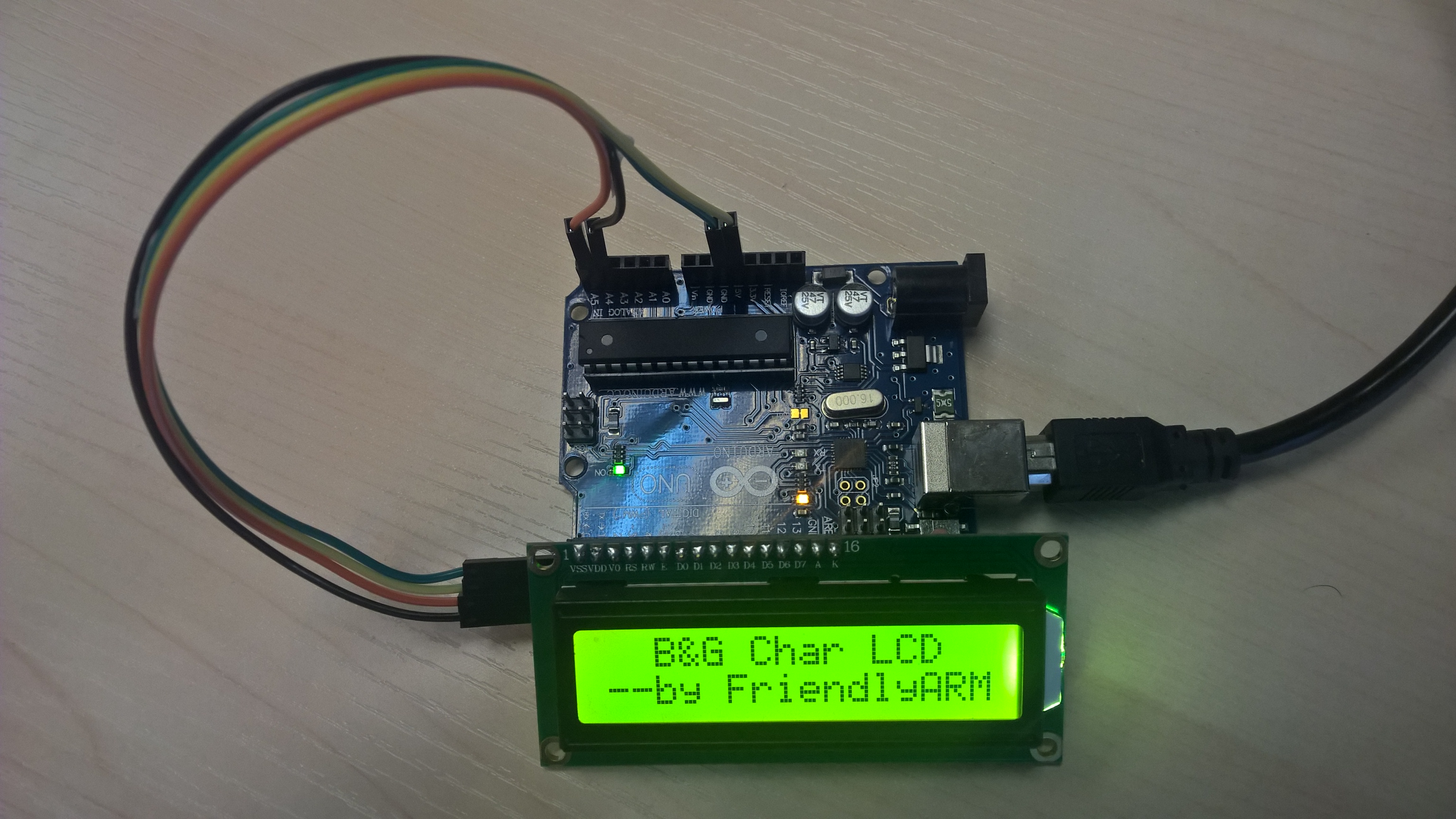
7.3 Compile & Run Test Program
All the matrix modules' code samples for Arduino are maintained on GitHub - https://github.com/friendlyarm/matrix-arduino.git
Clone the matrix code from GitHub
$ git clone git://github.com/friendlyarm/matrix-arduino.git
If this is successful a "matrix-arduino" directory will be generated, which will contain all the matrix modules' code samples.
Copy the entire directory "matrix-i2c_lcd1602" to "Arduino_IDE/libraries"
$ cd matrix-arduino
$ cp matrix-i2c_lcd1602 Arduino_IDE/libraies -r
Start Arduino IDE
Click on File->Examples->matrix-i2c_lcd1602->displaychar and run the test program.
Click on upload and run the test program.
7.4 Code Sample
#include <Wire.h>
#include <LiquidCrystal_I2C.h>

// set the LCD address to 0x27 for a 16 chars and 2 line display
LiquidCrystal_I2C lcd(0x27,16,2);

void setup()
{
  lcd.init();
  lcd.backlight();
  lcd.setCursor(2, 0);
  lcd.print("B&G Char LCD");
  lcd.setCursor(0, 1);
  lcd.println("--by FriendlyARM");
}

void loop()
{
}
8 Resources
9 Update Log
9.1 Feb-23-2016
- Added the description for "NanoPi 2 branch" in Section 4
- Added Section 5: Connect to NanoPi 2
9.2 June-19-2016
- Re-organized and simplified wiki
