Difference between revisions of "4x USB 3.0 HAT for M4"
From FriendlyELEC WiKi
(Created page with "==Features== Back * '''USB 3.0''' ** based on VL805 USB 3.0 host Controller, via a single PCIe 2.0 Lane ** 4x USB 3.0 Share 5Gbps Bandwid...") |
(→Features) |
||
| (10 intermediate revisions by the same user not shown) | |||
| Line 1: | Line 1: | ||
==Features== | ==Features== | ||
| − | [[File: | + | [[File:NanoPi_M4_USB_HAT-01B.jpg||thumb|Overview]] |
| + | [[File:NanoPi_M4_USB_HAT-A01.jpg||thumb|Front]] | ||
| + | [[File:NanoPi_M4_USB_HAT-B01.jpg||thumb|Back]] | ||
| + | [[File:NanoPi_M4_with_USB_HAT-B01.jpg||thumb|M4 with USB HAT]] | ||
| + | |||
* '''USB 3.0''' | * '''USB 3.0''' | ||
** based on VL805 USB 3.0 host Controller, via a single PCIe 2.0 Lane | ** based on VL805 USB 3.0 host Controller, via a single PCIe 2.0 Lane | ||
| − | ** 4x USB 3.0 | + | ** 4x USB 3.0 share 5Gbps Bandwidth |
** fully backward compatible with USB 2.0 and 1.1 specifications | ** fully backward compatible with USB 2.0 and 1.1 specifications | ||
* '''USB 2.0''' | * '''USB 2.0''' | ||
** Two 4-PIN PH2.0 USB 2.0 host connectors, independent bandwidth | ** Two 4-PIN PH2.0 USB 2.0 host connectors, independent bandwidth | ||
* '''Power''' | * '''Power''' | ||
| − | ** | + | ** One 5.5*2.1mm DC-Jack and One 4Pin PH2.0 connector for 12V Power Input |
** The output current of the 12V to 5V DC/DC regulator is up to 8A | ** The output current of the 12V to 5V DC/DC regulator is up to 8A | ||
** One PowerKey button | ** One PowerKey button | ||
| Line 15: | Line 19: | ||
* '''GPIO''' | * '''GPIO''' | ||
** ALL the signals of the NanoPi M4's 40-PIN connector are populated | ** ALL the signals of the NanoPi M4's 40-PIN connector are populated | ||
| − | + | [[File:M4_USB_HAT_layout.jpg|600px]] | |
| − | [[File: | + | |
==Block== | ==Block== | ||
[[File:M4_USB_HAT_Block.jpg|600px]] | [[File:M4_USB_HAT_Block.jpg|600px]] | ||
| − | == | + | ==USB3 19Pin IDC== |
| − | * 2D CAD file [http://wiki.friendlyarm.com/wiki/images/ | + | {| class="wikitable" |
| + | ! style="font-weight:bold; background-color:#34cdf9;" | Signal | ||
| + | ! style="background-color:#34cdf9;" | Pin# | ||
| + | ! style="background-color:#34cdf9;" | Pin# | ||
| + | ! style="font-weight:bold; background-color:#34cdf9;" | Signal | ||
| + | |- | ||
| + | | / | ||
| + | | style="font-weight:bold;" | / | ||
| + | | style="font-weight:bold;" | 1 | ||
| + | | 5V | ||
| + | |- | ||
| + | | 5V | ||
| + | | style="font-weight:bold;" | 19 | ||
| + | | style="font-weight:bold;" | 2 | ||
| + | | USB3 SSRX-_C | ||
| + | |- | ||
| + | | USB3 SSRX-_D | ||
| + | | style="font-weight:bold;" | 18 | ||
| + | | style="font-weight:bold;" | 3 | ||
| + | | USB3 SSRX+_C | ||
| + | |- | ||
| + | | USB3 SSRX+_D | ||
| + | | style="font-weight:bold;" | 17 | ||
| + | | style="font-weight:bold;" | 4 | ||
| + | | GND | ||
| + | |- | ||
| + | | GND | ||
| + | | style="font-weight:bold;" | 16 | ||
| + | | style="font-weight:bold;" | 5 | ||
| + | | USB3 SSTX-_C | ||
| + | |- | ||
| + | | USB3 SSTX-_D | ||
| + | | style="font-weight:bold;" | 15 | ||
| + | | style="font-weight:bold;" | 6 | ||
| + | | USB3 SSTX+_C | ||
| + | |- | ||
| + | | USB3 SSTX+_D | ||
| + | | style="font-weight:bold;" | 14 | ||
| + | | style="font-weight:bold;" | 7 | ||
| + | | GND | ||
| + | |- | ||
| + | | GND | ||
| + | | style="font-weight:bold;" | 13 | ||
| + | | style="font-weight:bold;" | 8 | ||
| + | | USB2 D-_C | ||
| + | |- | ||
| + | | USB2 D-_D | ||
| + | | style="font-weight:bold;" | 12 | ||
| + | | style="font-weight:bold;" | 9 | ||
| + | | USB2 D+_C | ||
| + | |- | ||
| + | | USB2 D+_D | ||
| + | | style="font-weight:bold;" | 11 | ||
| + | | style="font-weight:bold;" | 10 | ||
| + | | GND | ||
| + | |} | ||
| + | |||
| + | ==Mechanical Specification== | ||
| + | [[FILE:M4_USB_HAT_DIM.jpg|600px]] | ||
| + | * 2D CAD file [http://wiki.friendlyarm.com/wiki/images/b/b7/M4_USB_HAT_dxf.zip M4_USB_HAT_2D_DXF.zip] | ||
Latest revision as of 03:23, 26 June 2019
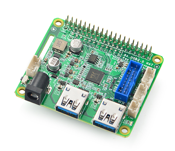
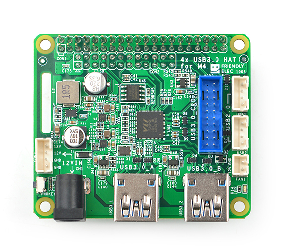
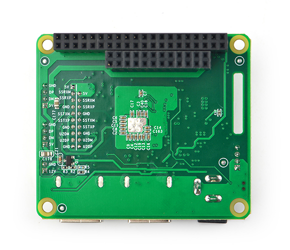
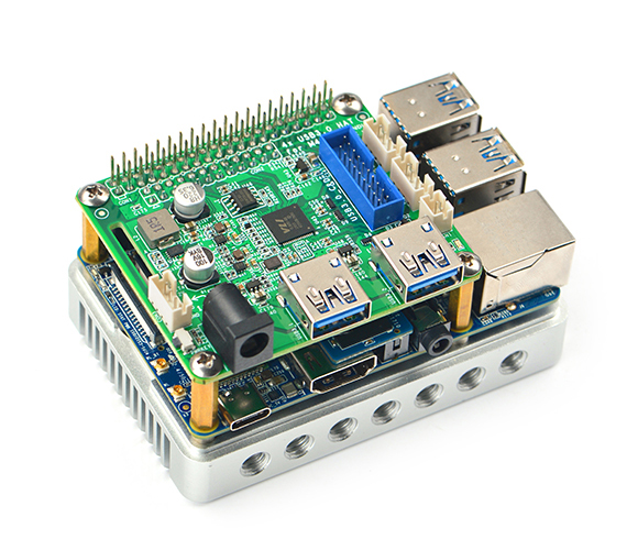
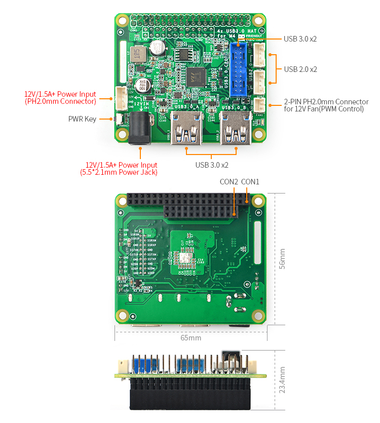
1 Features
- USB 3.0
- based on VL805 USB 3.0 host Controller, via a single PCIe 2.0 Lane
- 4x USB 3.0 share 5Gbps Bandwidth
- fully backward compatible with USB 2.0 and 1.1 specifications
- USB 2.0
- Two 4-PIN PH2.0 USB 2.0 host connectors, independent bandwidth
- Power
- One 5.5*2.1mm DC-Jack and One 4Pin PH2.0 connector for 12V Power Input
- The output current of the 12V to 5V DC/DC regulator is up to 8A
- One PowerKey button
- Heat dissipation
- One 2-PIN PH2.0 connector for fan. The 12V output is modulated by PWM1
- GPIO
- ALL the signals of the NanoPi M4's 40-PIN connector are populated
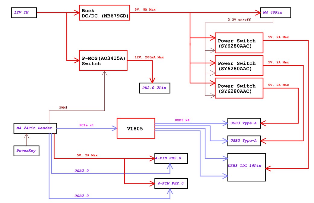
2 Block
3 USB3 19Pin IDC
| Signal | Pin# | Pin# | Signal |
|---|---|---|---|
| / | / | 1 | 5V |
| 5V | 19 | 2 | USB3 SSRX-_C |
| USB3 SSRX-_D | 18 | 3 | USB3 SSRX+_C |
| USB3 SSRX+_D | 17 | 4 | GND |
| GND | 16 | 5 | USB3 SSTX-_C |
| USB3 SSTX-_D | 15 | 6 | USB3 SSTX+_C |
| USB3 SSTX+_D | 14 | 7 | GND |
| GND | 13 | 8 | USB2 D-_C |
| USB2 D-_D | 12 | 9 | USB2 D+_C |
| USB2 D+_D | 11 | 10 | GND |
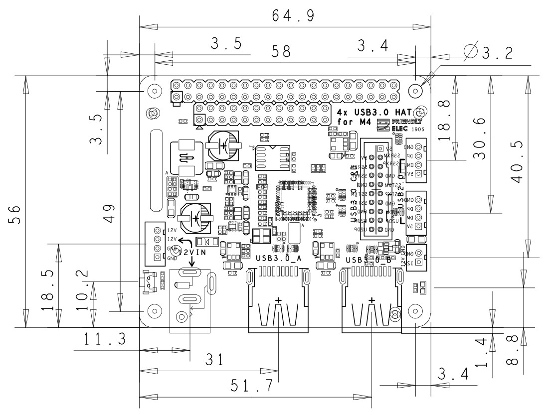
4 Mechanical Specification
- 2D CAD file M4_USB_HAT_2D_DXF.zip
