Difference between revisions of "NanoPi K2"
(→快速入门) |
(→Get Started) |
||
| Line 172: | Line 172: | ||
[[File:SanDisk MicroSD-02.png|frameless|100px|chuanyu MicroSD 8G]] | [[File:SanDisk MicroSD-02.png|frameless|100px|chuanyu MicroSD 8G]] | ||
| − | === | + | ===Make an Installation TF Card=== |
| − | ==== | + | ====Boot OS from TF Card==== |
| − | + | Get the following files from [http://pan.baidu.com/s/1c2MQ1P2 download link]: <br /> | |
| − | * | + | * Get a 8G SDHC card |
::{| class="wikitable" | ::{| class="wikitable" | ||
|- | |- | ||
| − | |colspan=2| | + | |colspan=2|Image Files: |
|- | |- | ||
| − | |s905-android-sd4g-YYYYMMDD.img.zip || Android5. | + | |s905-android-sd4g-YYYYMMDD.img.zip || Android5.1 Image File |
|- | |- | ||
| − | |colspan=2| | + | |colspan=2|Flash Utility: |
|- | |- | ||
| − | |win32diskimager.rar || | + | |win32diskimager.rar || Windows utility. Under Linux users can use "dd" |
|- | |- | ||
|} | |} | ||
| − | * | + | * Extract an image file and win32diskimager.rar. Insert a TF card(at least 8G) into a Windows PC and run the win32diskimager utility as administrator. On the utility's main window select your TF card's drive, the wanted image file and click on "write" to start flashing the TF card. |
| − | * | + | * Insert this card into your NanoPi K2's BOOT slot and power on (with a 5V/2A power source). If both the green LED and blue LED are solid on this indicates your NanoPi K2 has successfully booted.<br /> |
| − | ==== | + | ====Make Installation Card under Linux Desktop==== |
| − | * 1) | + | *1) Insert your SD card into a host computer running Ubuntu and check your SD card's device name |
<syntaxhighlight lang="bash"> | <syntaxhighlight lang="bash"> | ||
dmesg | tail | dmesg | tail | ||
</syntaxhighlight> | </syntaxhighlight> | ||
| − | + | Search the messages output by "dmesg" for similar words like "sdc: sdc1 sdc2". If you can find them it means your SD card has been recognized as "/dev/sdc". Or you can check that by commanding "cat /proc/partitions". | |
| − | *2) | + | *2) Downlaod Linux script |
<syntaxhighlight lang="bash"> | <syntaxhighlight lang="bash"> | ||
git clone https://github.com/friendlyarm/sd-fuse_amlogic.git | git clone https://github.com/friendlyarm/sd-fuse_amlogic.git | ||
| Line 205: | Line 205: | ||
</syntaxhighlight> | </syntaxhighlight> | ||
| − | *3) | + | *3) Make Android SD Card |
<syntaxhighlight lang="bash"> | <syntaxhighlight lang="bash"> | ||
su | su | ||
./fusing.sh /dev/sdx | ./fusing.sh /dev/sdx | ||
</syntaxhighlight> | </syntaxhighlight> | ||
| − | ( | + | (Note: you need to replace "/dev/sdx" with the device name in your system)<br/> |
| − | + | When you run the script for the first time it will prompt you to download an image you have to hit “Y” within 10 seconds otherwise you will miss the download | |
====NanoPi K2 扩展TF卡分区==== | ====NanoPi K2 扩展TF卡分区==== | ||
Revision as of 01:50, 14 April 2017
Contents
[hide]1 Introduction
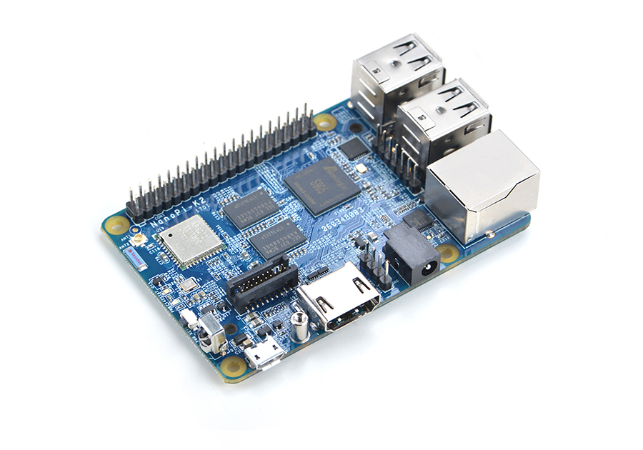
- FriendlyElec's NanoPi K2 uses Amlogic's 64-bit quad-core A53 S905 SoC. This SoC has internal Mali450 GPU. S905's dynamic frequency scales up to 2G Hz.In FriendlyElec's tests it can scale up to 2G. Its most significant feature is that it supports various video formats and has strong video decoding capability
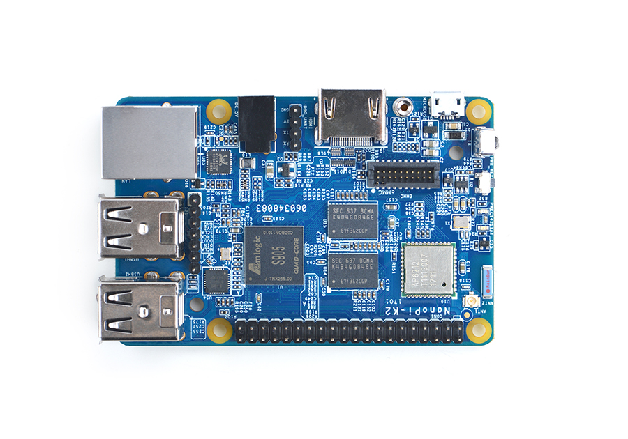
- The NanoPi K2 has 2GB DDR3 RAM, onboard WiFi & Bluetooth, 1000M Ethernet, USB, HDMI, IR and etc. It has a socket for external eMMC. It boots OS from a TF card. It has the same form factor and layout of interfaces and ports as the RPi 3. An Android image is ready for K2. Later on a Ubuntu image will be ready.
- A special feature of the NanoPi K2 is that it supports DVFS and can play high-definition video steams stably and smoothly. It is a good platform for applications such as advertisement machines, TV boxes, home entertainment appliances, multi-media devices and etc.
2 Hardware Spec
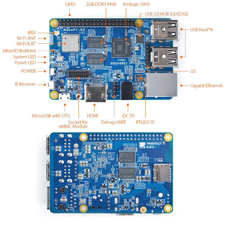
- SoC: Amlogic S905, Quad-core ARM Cortex-A53@1.5GHz, DVFS
- GPU: Penta-core ARM Mali™-450
- RAM: 2GB DDR3
- Network Connectivity: 10/100/1000M (RTL8211F)
- Wireless:802.11 b/g/n
- Bluetooth:4.0 dual mode
- Antenna: One onboard porcelain antenna shared by both WiFi and Bluetooth. One individual IPX interface.
- IR: Onboard IR receiver
- Audio: Via HDMI/Bluetooth
- eMMC interface: eMMC socket
- I2S: 7-Pin, 2.54mm pitch pin-header
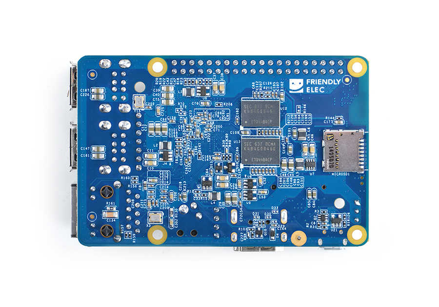
- SD: 1 x MicroSD slot
- USB Host: 4 x USB 2.0 Host, standard type A
- Micro USB: 1 x USB 2.0, OTG, power input and data transmission
- HDMI: HDMI 2.0, Type-A. It supports 4K video
- GPIO: 40-Pin, 2.54mm pitch pin-header including I2C, ADC, GPIO, UART, PWM, SPDIF and CVBS
- Serial debug port: 4-Pin, 2.54mm pitch single-row pin-header
- User Key: 1 x power key
- LED: 1 x power LED and 1 x status LED
- Power Interface: DC jack, MicroUSB
- Power Supply: DC 5V/2A
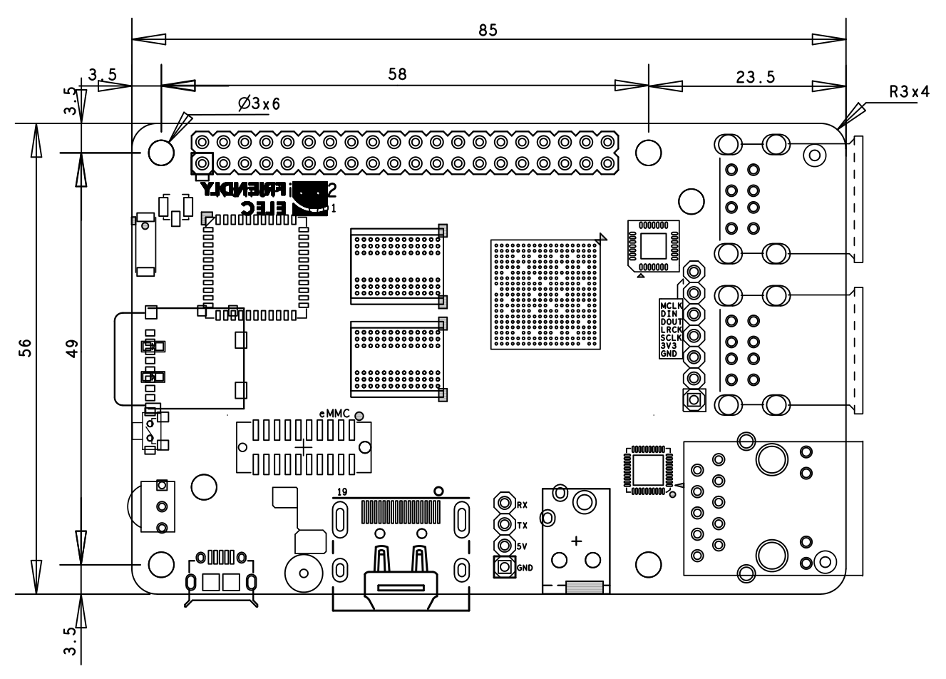
- PCB dimension: 56 x 85mm,6-layer, ENIG
3 Diagram, Layout and Dimension
3.1 Layout
- GPIO Pin Description
Pin# Name Pin# Name 1 SYS_3.3V 2 VDD_5V 3 GPIODV_24/I2C_SDA_A 4 VDD_5V 5 GPIODV_25/I2C_SCK_A 6 GND 7 GPIOY_0 8 GPIOY_13/UART_TX_C 9 DGND 10 GPIOY_13/UART_RX_C 11 GPIOY_1 12 GPIOY_16/PWM_A 13 GPIOY_2 14 GND 15 GPIOY_3 16 GPIOY_15/PWM_F 17 SYS_3.3V 18 GPIOY_4 19 GPIOY_5 20 GND 21 GPIOY_7 22 GPIOY_6 23 GPIOY_9 24 GPIOY_8 25 DGND 26 GPIOY_10 27 GPIODV_26/I2C_SDA_B 28 GPIODV_27/I2C_SCK_B 29 GPIOY_11/SPDIF_IN 30 GND 31 GPIOAO_5 32 GPIOY_12/SPDIF_OUT 33 GPIOH_3 34 GND 35 GPIOCLK_1 36 CVBS 37 AIN1 38 1.8V Vref Out 39 GND 40 AIN0
- eMMC Interface Pin Description
Pin# Name Pin# Name 1 eMMC_D0 2 eMMC_D1 3 eMMC_D2 4 eMMC_D3 5 eMMC_D4 6 eMMC_D5 7 eMMC_D6 8 eMMC_D7 9 eMMC_DS 10 GND 11 eMMC_CMD 12 eMMC_CLK 13 NC 14 GND 15 NC 16 1.8V OUT 17 eMMC_RST 18 3.3V OUT 19 GPIOY_5 20 GND
- Debug Port(UART0)
Pin# Name 1 GND 2 VDD_5V 3 UART_TX_AO_A 4 UART_RX_AO_A
- 7Pin I2S Interface Pin Description
Pin# Name 1 GND 2 SYS_3.3V 3 I2S_SCLK 4 I2S_LRCLK 5 I2S_DATA_OUT 6 I2S_DATA_IN 7 I2S_MCLK
- Notes
- SYS_3.3V: 3.3V power output
- VDD_5V: 5V power output5V. The input range is 4.7V ~ 5.6V
- All pins are 3.3V
- For more details refer to the document:NanoPi-K2-1701-Schematic.pdf
3.2 Board Dimension
- For more details refer to the document:NanoPi-K2-1701-dxf.zip
4 Get Started
4.1 Essentials You Need
Before starting to use your NanoPi K2 get the following items ready
- NanoPi K2
- MicroSD Card/TF Card: Class 10 or Above, minimum 8GB SDHC
- A DC 5V/2A power is a must
- HDMI monitor
- USB keyboard and USB mouse
- A host computer running Ubuntu 14.04 64 bit system
4.2 TF Cards We Tested
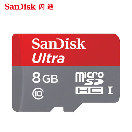
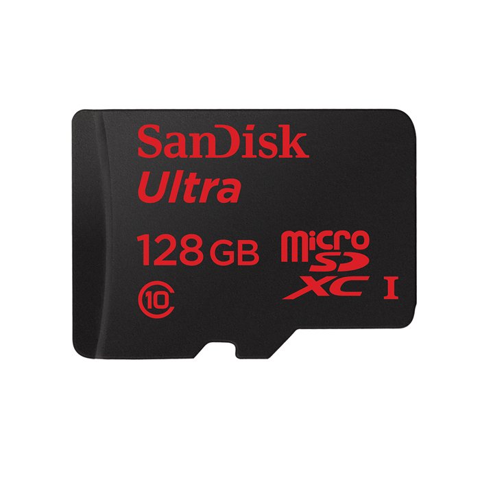
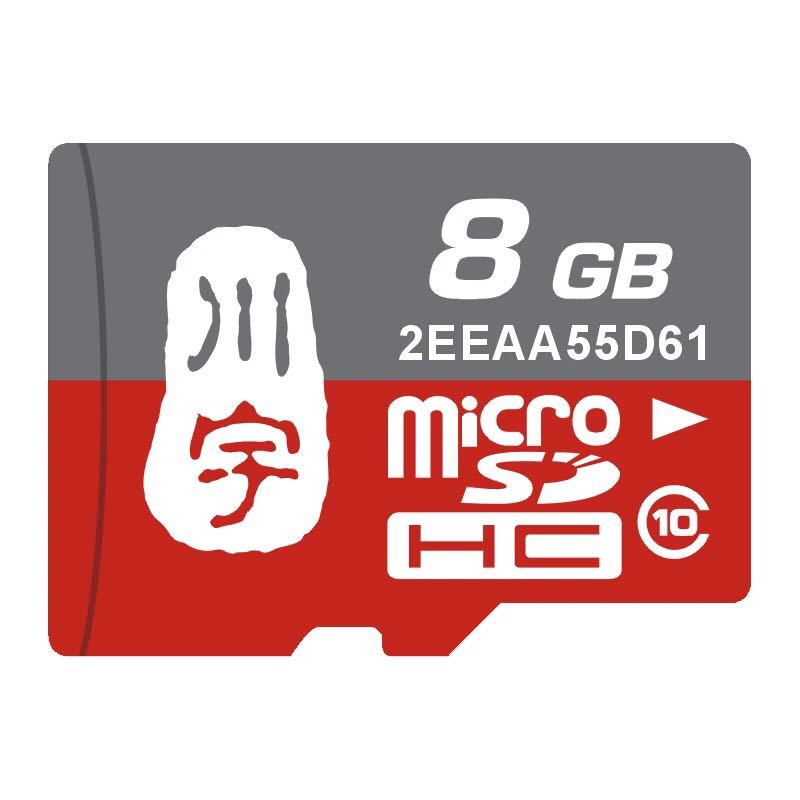
To make your NanoPi K2 boot and run fast we highly recommend you use a Class10 8GB SDHC TF card or a better one. The following cards are what we used in all our test cases presented here:
- SanDisk TF 8G Class10 Micro/SD TF card:
- SanDisk TF128G MicroSDXC TF 128G Class10 48MB/S:
- 川宇 8G C10 High Speed class10 micro SD card:
4.3 Make an Installation TF Card
4.3.1 Boot OS from TF Card
Get the following files from download link:
- Get a 8G SDHC card
Image Files: s905-android-sd4g-YYYYMMDD.img.zip Android5.1 Image File Flash Utility: win32diskimager.rar Windows utility. Under Linux users can use "dd"
- Extract an image file and win32diskimager.rar. Insert a TF card(at least 8G) into a Windows PC and run the win32diskimager utility as administrator. On the utility's main window select your TF card's drive, the wanted image file and click on "write" to start flashing the TF card.
- Insert this card into your NanoPi K2's BOOT slot and power on (with a 5V/2A power source). If both the green LED and blue LED are solid on this indicates your NanoPi K2 has successfully booted.
4.3.2 Make Installation Card under Linux Desktop
- 1) Insert your SD card into a host computer running Ubuntu and check your SD card's device name
dmesg | tail
Search the messages output by "dmesg" for similar words like "sdc: sdc1 sdc2". If you can find them it means your SD card has been recognized as "/dev/sdc". Or you can check that by commanding "cat /proc/partitions".
- 2) Downlaod Linux script
git clone https://github.com/friendlyarm/sd-fuse_amlogic.git
cd sd-fuse_amlogic
- 3) Make Android SD Card
su
./fusing.sh /dev/sdx
(Note: you need to replace "/dev/sdx" with the device name in your system)
When you run the script for the first time it will prompt you to download an image you have to hit “Y” within 10 seconds otherwise you will miss the download
4.3.3 NanoPi K2 扩展TF卡分区
- Android扩展分区,要在pc上执行下列操作:
sudo umount /dev/sdx?
sudo parted /dev/sdx unit % resizepart 4 100 unit MB print
sudo resize2fs -f /dev/sdx4
(注:/dev/sdx请替换为实际的SD卡设备文件名)
4.3.4 关于HDMI分辨率
对于HDMI的显示模式,Android则是会通过EDID获得HDMI设备如电视机所支持的显示模式,然后自动选择一个合适的分辨率。
4.4 运行Android
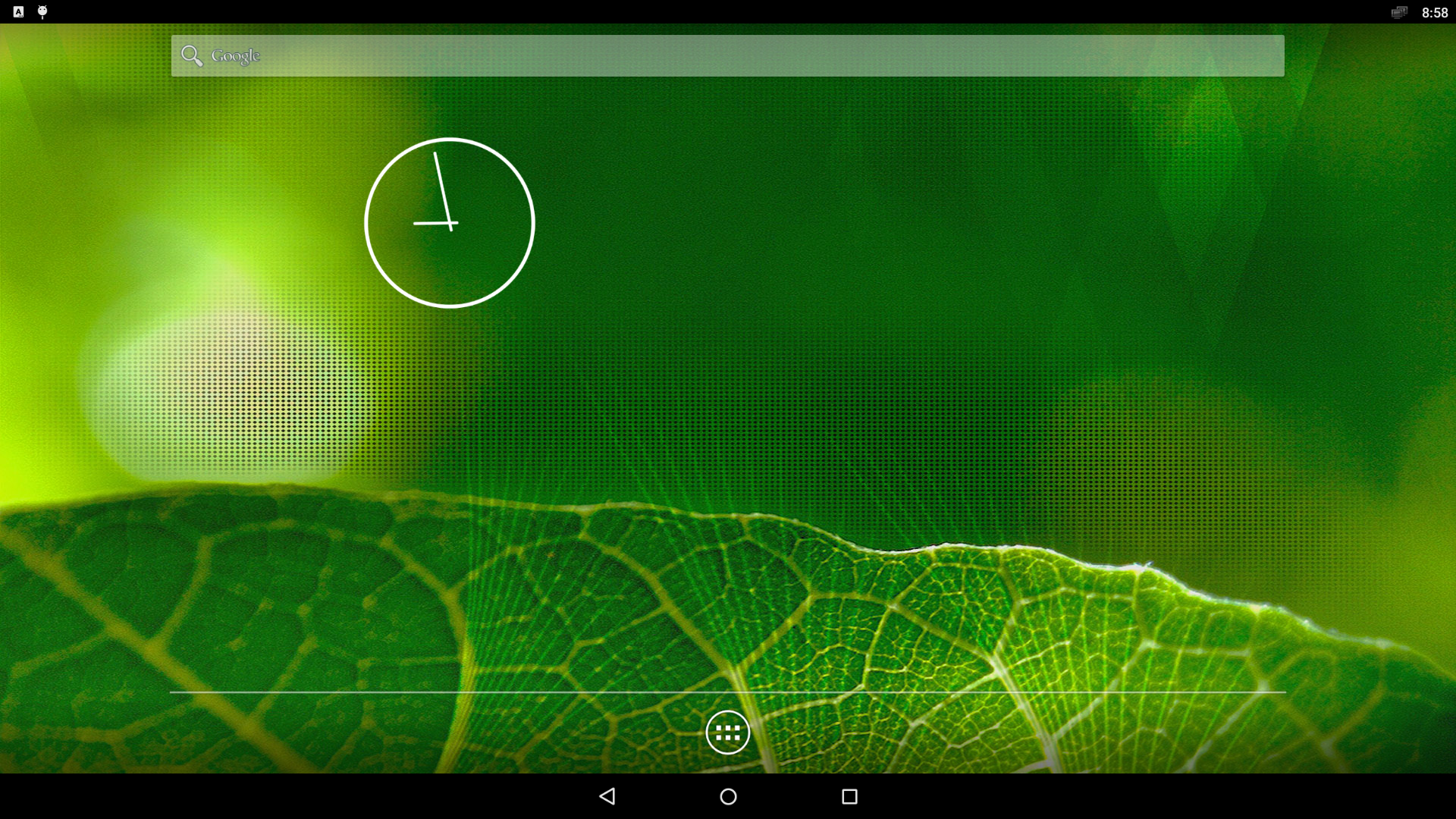
- 将制作好SD卡插入NanoPi K2,连接HDMI,最后接电源,NanoPi K2会从SD卡启动。你可以看到板上PWR灯以及蓝灯常亮,这说明系统已经开始启动了,同时电视上也将能看到系统启动的画面。
- 如同所有PC, 正确的关机对NanoPi K2而言很重要,否则可能会损坏安装在MicroSD卡中的系统文件,导致下次无法顺利启动运行,如要关机,直接按PWR按键即可。
5 如何编译系统
5.1 安装交叉编译器
- 安装ARMv7交叉编译器
编译U-Boot需要ARMv7的交叉编译器,首先下载并解压编译器:
git clone https://github.com/friendlyarm/prebuilts.git
sudo mkdir -p /opt/FriendlyARM/toolchain
sudo tar xf prebuilts/gcc-x64/arm-cortexa9-linux-gnueabihf-4.9.3.tar.xz -C /opt/FriendlyARM/toolchain/
然后将编译器的路径加入到PATH中,用vi编辑vi ~/.bashrc,在末尾加入以下内容:
export PATH=/opt/FriendlyARM/toolchain/4.9.3/bin:$PATH
export GCC_COLORS=auto
执行一下~/.bashrc脚本让设置立即在当前shell窗口中生效,注意"."后面有个空格:
. ~/.bashrc这个编译器是64位的,不能在32位的Linux系统上运行,安装完成后,你可以快速的验证是否安装成功:
arm-linux-gcc -v
Using built-in specs.
COLLECT_GCC=arm-linux-gcc
COLLECT_LTO_WRAPPER=/opt/FriendlyARM/toolchain/4.9.3/libexec/gcc/arm-cortexa9-linux-gnueabihf/4.9.3/lto-wrapper
Target: arm-cortexa9-linux-gnueabihf
Configured with: /work/toolchain/build/src/gcc-4.9.3/configure --build=x86_64-build_pc-linux-gnu
--host=x86_64-build_pc-linux-gnu --target=arm-cortexa9-linux-gnueabihf --prefix=/opt/FriendlyARM/toolchain/4.9.3
--with-sysroot=/opt/FriendlyARM/toolchain/4.9.3/arm-cortexa9-linux-gnueabihf/sys-root --enable-languages=c,c++
--with-arch=armv7-a --with-tune=cortex-a9 --with-fpu=vfpv3 --with-float=hard
...
Thread model: posix
gcc version 4.9.3 (ctng-1.21.0-229g-FA)
- 安装AArch64交叉编译器
编译U-Boot和Linux需要AArch64的交叉编译器,可使用linaro toolchain:
wget http://releases.linaro.org/components/toolchain/binaries/4.9-2017.01/aarch64-linux-gnu/gcc-linaro-4.9.4-2017.01-x86_64_aarch64-linux-gnu.tar.xz
tar xf gcc-linaro-4.9.4-2017.01-x86_64_aarch64-linux-gnu.tar.xz
export PATH=~/gcc-linaro-4.9.4-2017.01-x86_64_aarch64-linux-gnu/bin:$PATH
可以修改 ~/.bashrc 将编译器的路径加入到PATH中。
5.2 编译U-Boot
下载U-Boot源代码并编译,注意分支是nanopi-k2-v2015.01:
git clone https://github.com/friendlyarm/uboot.git
cd uboot
git checkout nanopi-k2-v2015.01
make nanopi-k2_defconfig
make
编译成功结束后您将获得fip/gxb/u-boot.bin,可使用以下命令直接更新SD卡:
sudo ./fusing.sh /dev/sdc
您也可以通过fastboot来更新正在运行的NanoPi K2板上SD的U-Boot,方法如下:
1) 在电脑上先用命令 sudo apt-get install android-tools-fastboot 安装 fastboot 工具;
2) 用串口配件连接NanoPi K2和电脑,在上电启动的2秒内,在串口终端上按下回车,进入 u-boot 的命令行模式;
3) 在u-boot 命令行模式下输入命令 fastboot usb 回车,进入 fastboot 模式;
4) 用microUSB线连接NanoPi K2和电脑,在电脑上输入以下命令烧写u-boot.bin:
fastboot flash bootloader fip/gxb/u-boot.bin
5.3 编译Linux kernel
5.3.1 编译内核
- 下载内核源代码
git clone https://github.com/friendlyarm/linux.git
cd linux
git checkout nanopi-k2-3.14.y
NanoPi K2内核所属的分支是nanopi-k2-3.14.y,在开始编译前先切换分支。
- 编译Android内核
make ARCH=arm64 nanopi-k2_defconfig
make ARCH=arm64 CROSS_COMPILE=aarch64-linux-gnu- Image nanopi-k2.dtb
编译成功结束后,即会生成新的 arch/arm64/boot/dts/amlogic/nanopi-k2.dtb 和 arch/arm64/boot/Image ,用于替换掉SD卡boot分区下对应的文件。
5.3.2 如何使用新编译的内核
- 更新SD卡上的内核
如果您是使用SD卡启动Android,则在PC上复制为Android编译的Image 和nanopi-k2.dtb 到SD卡的boot分区(即分区1,设备是/dev/sdX1)即可。
- 通过adb直接更新
如果想直接更新正在运行中的板子,可通过adb将新的文件push到板子上,然后reboot即可,具体如下:
adb shell mount -t ext4 /dev/block/mmcblk0p1 /storage/sdcard1/
adb push arch/arm64/boot/Image /storage/sdcard1/
adb push arch/arm64/boot/dts/amlogic/nanopi-k2.dtb /storage/sdcard1/
adb reboot
- 更新Android中预先编译的文件
如果想要生成新的Android boot.img,则需要使用新生成的文件替换Android源代码目录device/friendly-arm/nanopi-k2-kernel 下对应的文件,然后编译Android即可。
5.4 编译Android
- 搭建编译环境
搭建编译Android的环境建议使用64位的Ubuntu 14.04,安装需要的包即可。
sudo apt-get install bison g++-multilib git gperf libxml2-utils make python-networkx zip
sudo apt-get install flex libncurses5-dev zlib1g-dev gawk minicom
更多说明可查看 https://source.android.com/source/initializing.html 。
- 下载Android5.1源代码
Android源代码的下载需要使用repo,其安装和使用请查看 https://source.android.com/source/downloading.html 。
mkdir android && cd android
repo init -u https://github.com/friendlyarm/android_manifest.git -b nanopi-k2-lollipop
repo sync
其中“android”是指工作目录。
- 编译系统
source build/envsetup.sh
lunch nanopi_k2-userdebug
make -j8
编译成功完成后,目录 out/target/product/nanopi-k2 下包含可用于烧写的image文件。
filename partition Description u-boot.bin bootloader - boot.img boot - cache.img cache - userdata.img userdata - system.img system - partmap.txt - 分区描述文件
- 烧写到SD卡
如果是采用SD卡启动Android,可复制编译生成的image文件到sd-fuse_amlogic/android/ 下,使用脚本即可烧到到SD卡,具体请查看#在Linux Desktop下通过脚本制作。
- 使用fastboot更新
板子启动后通过串口快速按任意键进入uboot命令行模式,输入命令fastboot usb即可更新Android。
连接USB线,然后PC端输入以下命令:
cd out/target/product/nanopi-k2
sudo fastboot flash boot boot.img
sudo fastboot flash cache cache.img
sudo fastboot flash userdata userdata.img
sudo fastboot flash system system.img
sudo fastboot reboot
