Difference between revisions of "Matrix - Buzzer/zh"
From FriendlyELEC WiKi
(r) |
(→连接NanoPC-T2) |
||
| (50 intermediate revisions by 2 users not shown) | |||
| Line 1: | Line 1: | ||
[[Matrix - Buzzer|English]] | [[Matrix - Buzzer|English]] | ||
==介绍== | ==介绍== | ||
| − | [[File: | + | [[File:Buzzer.jpg|thumb|Buzzer]] |
| − | + | * 模块Matrix-Buzzer是一个无源蜂鸣器。它内部不带震荡源,所以如果用直流信号无法令其鸣叫,必须用2K~5K的方波去驱动它。 | |
| + | * 广泛应用于计算机、报警器、电子玩具、汽车电子设备、定时器等电子产品中作发声器件。 | ||
==特性== | ==特性== | ||
| Line 8: | Line 9: | ||
* 尺寸为 16x24mm | * 尺寸为 16x24mm | ||
* PCB尺寸(mm):16x24 | * PCB尺寸(mm):16x24 | ||
| − | [[File: | + | [[File:buzzerpcb.png|frameless|400px|无源蜂鸣器PCB]] |
| − | + | * 引脚说明: | |
| − | = | + | {| class="wikitable" |
| − | + | |- | |
| − | + | |名称 || 描述 | |
| + | |- | ||
| + | |V || 电源5V | ||
| + | |- | ||
| + | |G || 地 | ||
| + | |- | ||
| + | |S || 输入,接PWM | ||
| + | |} | ||
| − | === | + | ==工作原理== |
| − | + | 无源蜂鸣器没有内部驱动电路,因此无源蜂鸣器工作的理想信号是方波。如果给预直流信号蜂鸣器是不响应的,因为磁路恒定,钼片不能振动发音。所以GPIO驱动无源蜂鸣器需要把GPIO的值拉高以后再拉低来产生振荡,而振荡的频率由GPIO从高拉低之间的时间决定,可以通过改变这个时间使无源蜂鸣器发出频率不同的声音。 | |
| − | + | ||
| − | + | ||
| + | ==硬件连接== | ||
| + | ===连接NanoPi 2=== | ||
| + | 参考下图连接模块:<br> | ||
| + | [[File:Matrix-Buzzer_nanopi_2.jpg|frameless|600px|Matrix-Buzzer_nanopi_2]] | ||
| + | |||
| + | 连接说明: | ||
| + | {| class="wikitable" | ||
| + | |- | ||
| + | |Matrix-Buzzer || NanoPi 2 | ||
| + | |- | ||
| + | |G || Pin6 | ||
| + | |- | ||
| + | |V || Pin4 | ||
| + | |- | ||
| + | |S || Pin22 | ||
| + | |} | ||
| + | |||
| + | ===连接NanoPi M2 / NanoPi 2 Fire=== | ||
| + | NanoPi M2和NanoPi 2 Fire的40 Pin引脚定义是一模一样的,所以它们操作Matrix配件的步骤是一样的,这里仅以NanoPi M2为例。<br> | ||
| + | 参考下图连接模块:<br> | ||
| + | [[File:Matrix-Buzzer_nanopi_m2.jpg|frameless|600px|Matrix-Buzzer_nanopi_m2]] | ||
| + | |||
| + | 连接说明: | ||
| + | {| class="wikitable" | ||
| + | |- | ||
| + | |Matrix-Buzzer || NanoPi M2 | ||
| + | |- | ||
| + | |G || Pin6 | ||
| + | |- | ||
| + | |V || Pin4 | ||
| + | |- | ||
| + | |S || Pin12 | ||
| + | |} | ||
| + | |||
| + | ===连接NanoPi M3=== | ||
| + | 参考下图连接模块:<br> | ||
| + | [[File:Matrix-Buzzer_nanopi_m3.jpg|frameless|600px|Matrix-Buzzer_nanopi_m3]] | ||
| + | |||
| + | 连接说明: | ||
| + | {| class="wikitable" | ||
| + | |- | ||
| + | |Matrix-Buzzer || NanoPi M3 | ||
| + | |- | ||
| + | |G || Pin6 | ||
| + | |- | ||
| + | |V || Pin4 | ||
| + | |- | ||
| + | |S || Pin12 | ||
| + | |} | ||
| + | |||
| + | ===连接NanoPC-T2/NanoPC-T3=== | ||
| + | 由于NanoPC-T2跟NanoPC-T3的引脚是一样的,所以连接方式是一样的,这里仅以T2为例,参考下图连接模块:<br> | ||
| + | [[File:Matrix-Buzzer_nanopc_t2.jpg|frameless|600px|Matrix-Buzzer_nanopc_t2]] | ||
| + | |||
| + | 连接说明: | ||
| + | {| class="wikitable" | ||
| + | |- | ||
| + | |Matrix-Buzzer || NanoPC-T2 | ||
| + | |- | ||
| + | |S || Pin23 | ||
| + | |- | ||
| + | |V || Pin29 | ||
| + | |- | ||
| + | |G || Pin30 | ||
| + | |} | ||
| + | |||
| + | ==编译运行测试程序== | ||
| + | 启动开发板并运行Debian系统,进入系统后克隆Matrix代码仓库: | ||
| + | <syntaxhighlight lang="bash"> | ||
| + | $ apt-get update && apt-get install git | ||
| + | $ git clone https://github.com/friendlyarm/matrix.git | ||
</syntaxhighlight> | </syntaxhighlight> | ||
| + | 克隆完成后会得到一个名为matrix的目录。 | ||
| − | + | 编译并安装Matrix: | |
<syntaxhighlight lang="bash"> | <syntaxhighlight lang="bash"> | ||
| + | $ cd matrix | ||
| + | $ make && make install | ||
| + | </syntaxhighlight> | ||
| + | 运行测试程序: | ||
| + | <syntaxhighlight lang="bash"> | ||
| + | $ matrix-pwm | ||
| + | </syntaxhighlight> | ||
| + | 注意:此模块并不支持热插拔,启动系统前需要确保硬件连接正确。<br> | ||
| + | 运行效果如下:<br> | ||
| + | <syntaxhighlight lang="bash"> | ||
| + | Using default config: channel=0 freq=1000Hz duty=500 | ||
| + | Press enter to stop PWM | ||
| + | </syntaxhighlight> | ||
| + | 可以听到蜂鸣器鸣叫,占空比的范围为0-1000,键盘敲入回车键停止pwm输出。 | ||
| + | |||
| + | ==代码说明== | ||
| + | 所有的开发板都共用一套Matrix代码,本模块的测试示例代码为matrix-pwm,内容如下: | ||
| + | <syntaxhighlight lang="c"> | ||
| + | int main(int argc, char ** argv) | ||
| + | { | ||
| + | int Hz, duty, board; | ||
| + | |||
| + | if ((board = boardInit()) < 0) { | ||
| + | printf("Fail to init board\n"); | ||
| + | return -1; | ||
| + | } | ||
| + | |||
| + | system("modprobe "DRIVER_MODULE); | ||
| + | signal(SIGINT, intHandler); | ||
| + | if (argc == 4) { | ||
| + | // Usage:matrix-pwm channel freq duty[0~1000] | ||
| + | pwm = atoi(argv[1]); | ||
| + | Hz = atoi(argv[2]); | ||
| + | duty = atoi(argv[3]); | ||
| + | } else { | ||
| + | Hz = 1000; | ||
| + | duty = 500; | ||
| + | printf("Using default config: channel=%d freq=%dHz duty=%d\n", pwm, Hz, duty); | ||
| + | } | ||
| + | if (PWMPlay(pwm, Hz, duty) == -1) { | ||
| + | printf("Fail to output PWM\n"); | ||
| + | } | ||
| + | printf("Press enter to stop PWM\n"); | ||
| + | getchar(); | ||
| + | PWMStop(pwm); | ||
| + | system("rmmod "DRIVER_MODULE); | ||
| + | |||
| + | return 0; | ||
| + | } | ||
</syntaxhighlight> | </syntaxhighlight> | ||
| − | + | API说明参考维基:[[Matrix API reference manual/zh|Matrix API reference manual]] <br> | |
==相关资料== | ==相关资料== | ||
Latest revision as of 08:43, 10 November 2016
Contents
1 介绍
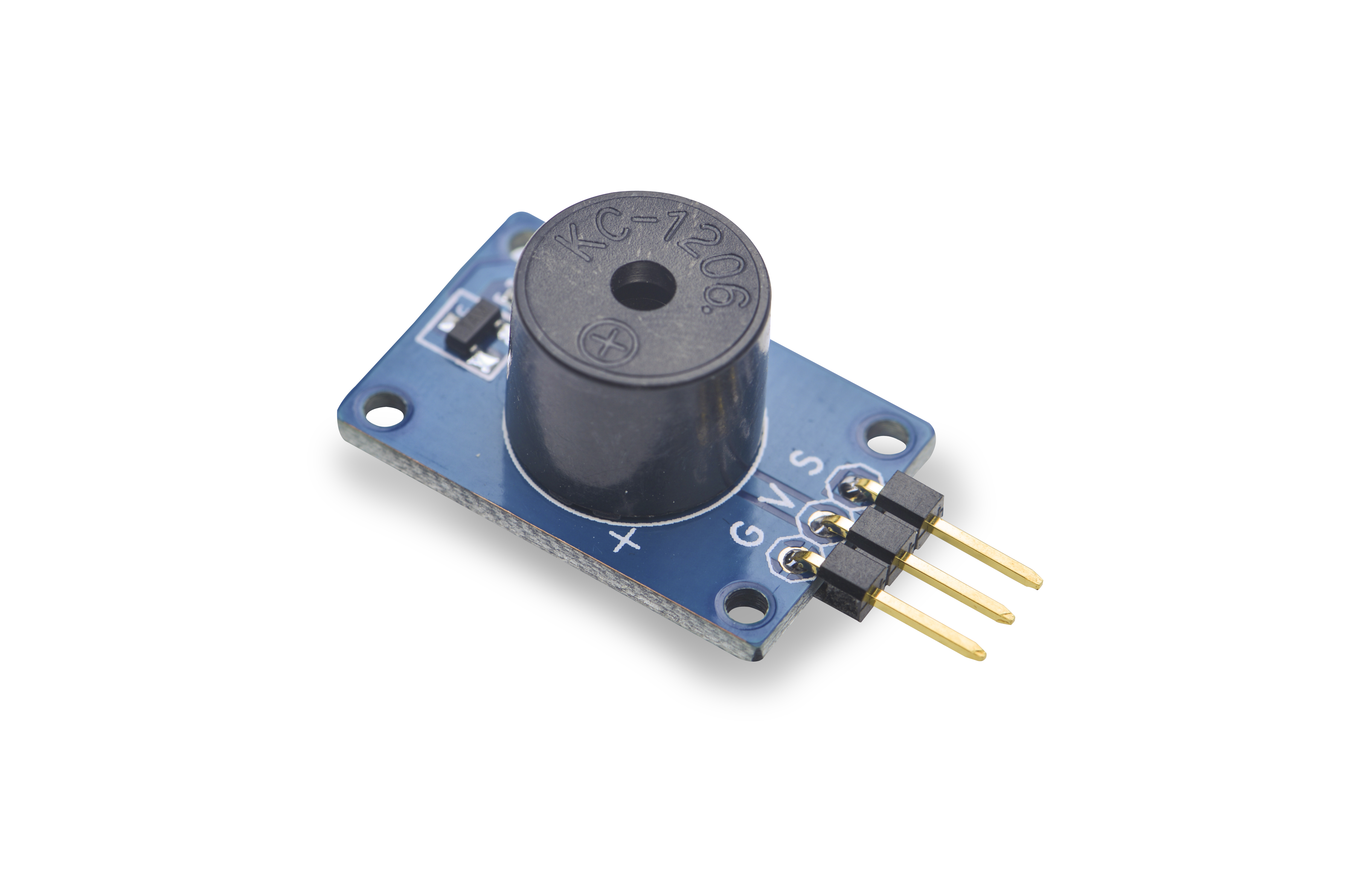
- 模块Matrix-Buzzer是一个无源蜂鸣器。它内部不带震荡源,所以如果用直流信号无法令其鸣叫,必须用2K~5K的方波去驱动它。
- 广泛应用于计算机、报警器、电子玩具、汽车电子设备、定时器等电子产品中作发声器件。
2 特性
- 使用标准的3 PIN接口
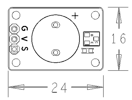
- 尺寸为 16x24mm
- PCB尺寸(mm):16x24
- 引脚说明:
| 名称 | 描述 |
| V | 电源5V |
| G | 地 |
| S | 输入,接PWM |
3 工作原理
无源蜂鸣器没有内部驱动电路,因此无源蜂鸣器工作的理想信号是方波。如果给预直流信号蜂鸣器是不响应的,因为磁路恒定,钼片不能振动发音。所以GPIO驱动无源蜂鸣器需要把GPIO的值拉高以后再拉低来产生振荡,而振荡的频率由GPIO从高拉低之间的时间决定,可以通过改变这个时间使无源蜂鸣器发出频率不同的声音。
4 硬件连接
4.1 连接NanoPi 2
连接说明:
| Matrix-Buzzer | NanoPi 2 |
| G | Pin6 |
| V | Pin4 |
| S | Pin22 |
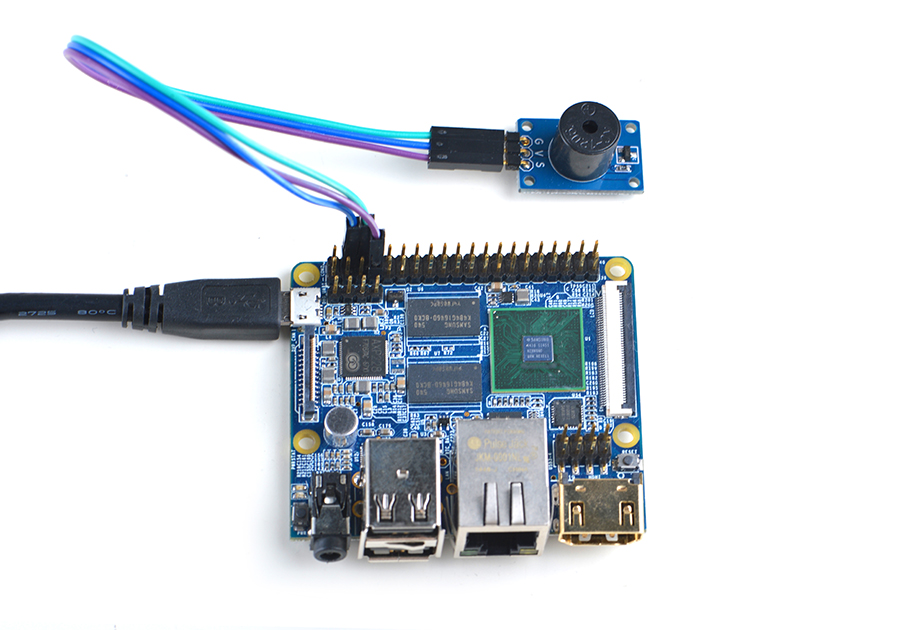
4.2 连接NanoPi M2 / NanoPi 2 Fire
NanoPi M2和NanoPi 2 Fire的40 Pin引脚定义是一模一样的,所以它们操作Matrix配件的步骤是一样的,这里仅以NanoPi M2为例。
参考下图连接模块:

连接说明:
| Matrix-Buzzer | NanoPi M2 |
| G | Pin6 |
| V | Pin4 |
| S | Pin12 |
4.3 连接NanoPi M3
参考下图连接模块:
Matrix-Buzzer_nanopi_m3
连接说明:
| Matrix-Buzzer | NanoPi M3 |
| G | Pin6 |
| V | Pin4 |
| S | Pin12 |
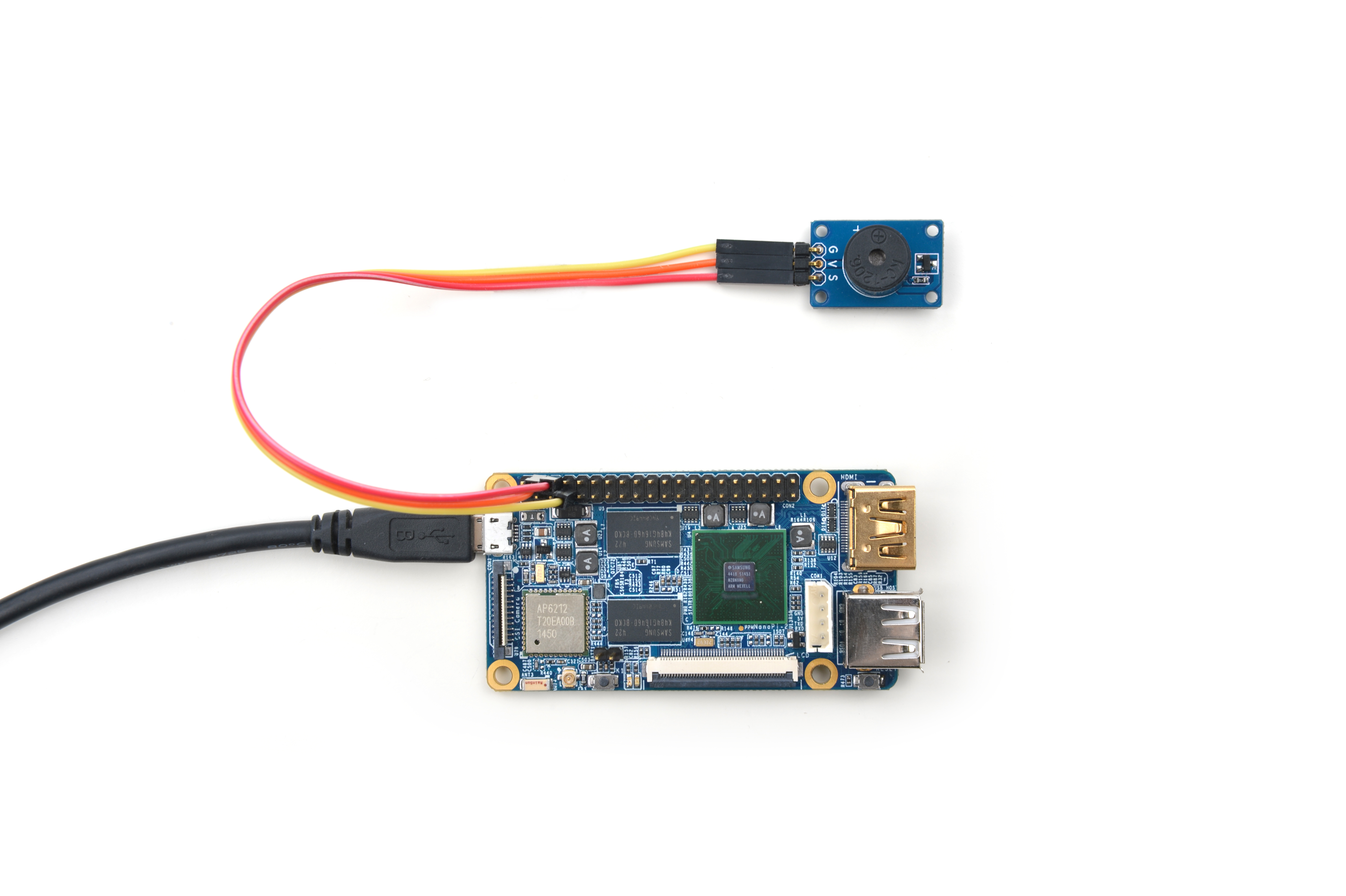
4.4 连接NanoPC-T2/NanoPC-T3
由于NanoPC-T2跟NanoPC-T3的引脚是一样的,所以连接方式是一样的,这里仅以T2为例,参考下图连接模块:
Matrix-Buzzer_nanopc_t2
连接说明:
| Matrix-Buzzer | NanoPC-T2 |
| S | Pin23 |
| V | Pin29 |
| G | Pin30 |
5 编译运行测试程序
启动开发板并运行Debian系统,进入系统后克隆Matrix代码仓库:
$ apt-get update && apt-get install git
$ git clone https://github.com/friendlyarm/matrix.git
克隆完成后会得到一个名为matrix的目录。
编译并安装Matrix:
$ cd matrix
$ make && make install
运行测试程序:
$ matrix-pwm注意:此模块并不支持热插拔,启动系统前需要确保硬件连接正确。
运行效果如下:
Using default config: channel=0 freq=1000Hz duty=500
Press enter to stop PWM
可以听到蜂鸣器鸣叫,占空比的范围为0-1000,键盘敲入回车键停止pwm输出。
6 代码说明
所有的开发板都共用一套Matrix代码,本模块的测试示例代码为matrix-pwm,内容如下:
int main(int argc, char ** argv)
{
    int Hz, duty, board;

    if ((board = boardInit()) < 0) {
        printf("Fail to init board\n");
        return -1;
    }

    system("modprobe "DRIVER_MODULE);
    signal(SIGINT, intHandler);
    if (argc == 4) {
        // Usage:matrix-pwm channel freq duty[0~1000]
        pwm = atoi(argv[1]);
        Hz = atoi(argv[2]);
        duty = atoi(argv[3]);
    } else {
        Hz = 1000;
        duty = 500;
        printf("Using default config: channel=%d freq=%dHz duty=%d\n", pwm, Hz, duty);
    }
    if (PWMPlay(pwm, Hz, duty) == -1) {
        printf("Fail to output PWM\n");
    }
    printf("Press enter to stop PWM\n");
    getchar();
    PWMStop(pwm);
    system("rmmod "DRIVER_MODULE);

    return 0;
}
API说明参考维基:Matrix API reference manual


