Difference between revisions of "NanoPi NEO Air"
(→配置无线网络) |
(→SSH登录) |
||
| Line 172: | Line 172: | ||
Save, exit and insert the TF card to your AIR. After power on your AIR and the blue LED is blinking for one minute you will be able to check AIR's IP address. | Save, exit and insert the TF card to your AIR. After power on your AIR and the blue LED is blinking for one minute you will be able to check AIR's IP address. | ||
| − | === | + | ===SSH Login=== |
| − | + | The NanoPi NEO AIR has no display interface. If you don't have a serial communication board to connect your AIR to a PC you can log in your AIR via SSH. In our example the AIR's IP address was 192.168.1.230 and we logged in AIR by using the following command: | |
<syntaxhighlight lang="bash"> | <syntaxhighlight lang="bash"> | ||
ssh root@192.168.1.230 | ssh root@192.168.1.230 | ||
</syntaxhighlight> | </syntaxhighlight> | ||
| − | + | The password is fa。 | |
===烧写系统到eMMC=== | ===烧写系统到eMMC=== | ||
Revision as of 08:14, 28 September 2016
Contents
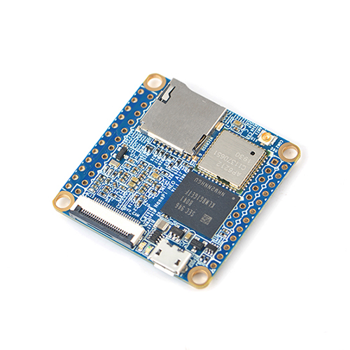
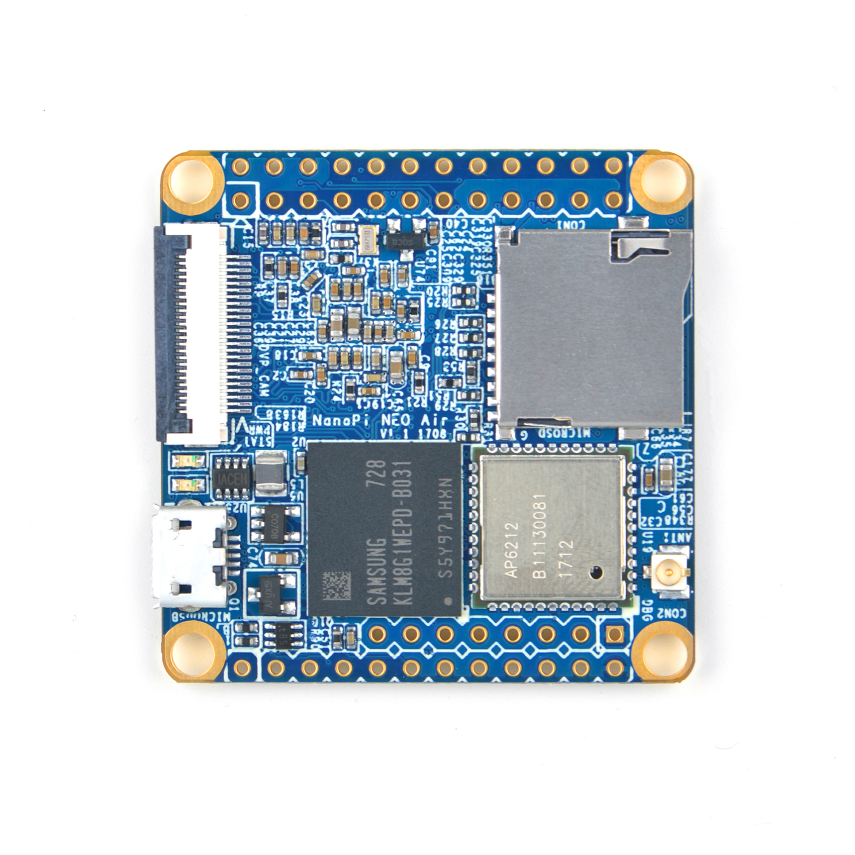
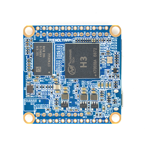
1 Introduction
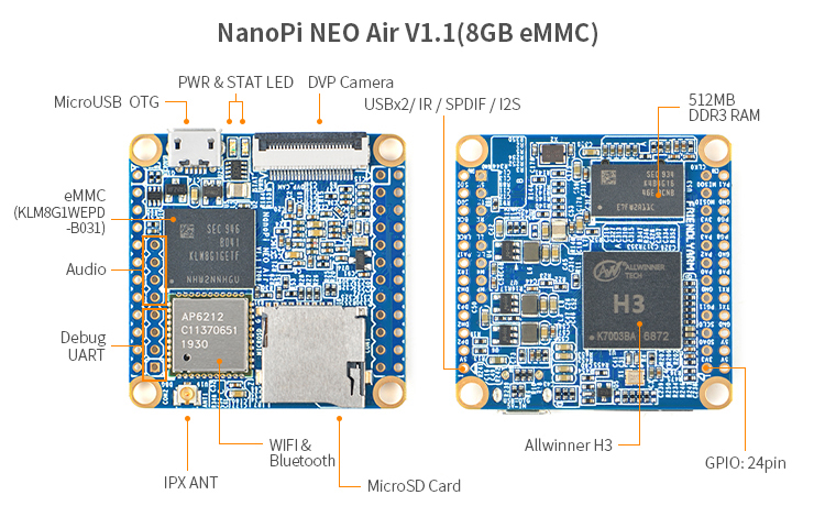
2 Specifications
- CPU: Allwinner H3, Quad-core Cortex-A7 Up to 1.2GHz
- RAM: 512MB DDR3 RAM
- Storage: 8GB eMMC
- WiFi: 802.11b/g/n
- Bluetooth: 4.0 dual mode
- MicroSD Slot x 1
- GPIO: 2.54mm pitch 24pin. It includes UART, SPI, I2C, IO etc
- PCB Size: 40 x 40mm
- Power Supply: DC 5V/2A
- OS/Software: u-boot, UbuntuCore
- Weight: 7.5g(WITHOUT Pin-headers); 9.7g(WITH Pin-headers)
3 Diagram, Layout and Dimension
3.1 Layout
- GPIO Pin Description
Pin# Name Linux gpio Pin# Name Linux gpio 1 SYS_3.3V 2 VDD_5V 3 I2C0_SDA 4 VDD_5V 5 I2C0_SCL 6 GND 7 GPIOG11 203 8 UART1_TX/GPIOG6 198 9 GND 10 UART1_RX/GPIOG7 199 11 UART2_TX/GPIOA0 0 12 PWM1/GPIOA6 6 13 UART2_RTS/GPIOA2 2 14 GND 15 UART2_CTS/GPIOA3 3 16 UART1_RTS/GPIOG8 200 17 SYS_3.3V 18 UART1_CTS/GPIOG9 201 19 SPI0_MOSI/GPIOC0 64 20 GND 21 SPI0_MISO/GPIOC1 65 22 UART2_RX/GPIOA1 1 23 SPI0_CLK/GPIOC2 93 24 SPI0_CS/GPIOC3 67
- USB/Audio/IR Pin Description
NanoPi-NEO-AIR NanoPi-NEO-AIR Pin# Name Description Pin# Name Description 1 VDD_5V 5V Power Out 1 VDD_5V 5V Power Out 2 USB-DP1 USB1 DP Signal 2 USB-DP1 USB1 DP Signal 3 USB-DM1 USB1 DM Signal 3 USB-DM1 USB1 DM Signal 4 USB-DP2 USB2 DP Signal 4 USB-DP2 USB2 DP Signal 5 USB-DM2 USB2 DM Signal 5 USB-DM2 USB2 DM Signal 6 GPIOL11/IR-RX GPIOL11 or IR Receive 6 GPIOL11/IR-RX GPIOL11 or IR Receive 7 SPDIF-OUT/GPIOA17 GPIOA17 or SPDIF-OUT 7 SPDIF-OUT/GPIOA17 GPIOA17 or SPDIF-OUT 8 MICIN1P Microphone Positive Input 8 PCM0_SYNC/I2S0_LRC I2S/PCM Sample Rate Clock/Sync 9 MICIN1N Microphone Negative Input 9 PCM0_CLK/I2S0_BCK I2S/PCM Sample Rate Clock 10 LINEOUTR LINE-OUT Right Channel Output 10 PCM0_DOUT/I2S0_SDOUT I2S/PCM Serial Bata Output 11 LINEOUTL LINE-OUT Left Channel Output 11 PCM0_DIN/I2S0_SDIN I2S/PCM Serial Data Input 12 GND 0V 12 GND 0V
- Debug Port(UART0)
Pin# Name 1 GND 2 VDD_5V 3 UART_TXD0 4 UART_RXD0
- Note:
- SYS_3.3V: 3.3V power output
- VVDD_5V: 5V power input/output. When the external device’s power is greater than the MicroUSB's the external device is charging the board otherwise the board powers the external device. The input range is 4.7V ~ 5.6V
- All pins are 3.3V, output current is 5mA
- For more details refer to the document:[]
3.2 Dimensional Diagram
File:NanoPi-NEO-AIR-1606-dimensions.png
4 Get Started
4.1 Essentials You Need
Before starting to use your NanoPi NEO AIR get the following items ready
- NanoPi NEO AIR
- microSD Card/TFCard: Class 10 or Above, minimum 8GB SDHC
- microUSB power. A 5V/2A power is a must
- A Host computer running Ubuntu 14.04 64 bit system
4.2 TF Cards We Tested
To make your NanoPi NEO AIR boot and run fast we highly recommand you use a Class10 8GB SDHC TF card or a better one. The following cards are what we used in all our test cases presented here:
- SanDisk TF 8G Class10 Micro/SD TF card:
- SanDisk TF128G MicroSDXC TF 128G Class10 48MB/S:
- 川宇 8G C10 High Speed class10 micro SD card:
4.3 Make an Installation TF Card
4.3.1 Boot NanoPi NEO AIR from TF Card
- Get the following files from here download link to download image files and the flashing utility:
Image Files nanopi-air-core-qte-sd4g.img.zip Ubuntu core with Qt Embedded nanopi-air-eflasher-sd8g.img.zip eflasher image which can be used to Flash image files to eMMC Flash Utility win32diskimager.rar Windows utility. Under Linux users can use "dd"
- Uncompress these files. Insert a TF card(at least 4G) into a Windows PC and run the win32diskimager utility as administrator. On the utility's main window select your TF card's drive, the wanted image file and click on "write" to start flashing the SD card till it is done.
- Insert this card into your AIR's MicroSD card slot and power on (with a 5V/2A power source). If the blue LED is blinking this indicates your AIR has successfully booted.
4.3.2 Flash image to eMMC with eflasher
- The eflasher is a utility FriendlyARM developed based on UbuntuCore. It can be used to flash OS image files to eMMC.
- Extract the nanopi-air-eflasher-sd8g.img.zip package and win32diskimager.rar. Insert a TF card(at least 8G) into a Windows PC and run the win32diskimager utility as administrator. On the utility's main window select your TF card's drive, the wanted image file and click on "write" to start flashing the TF card.
- Insert this card into your AIR and power on (with a 5V/2A power source) the board. If the blue LED is blinking it indicates your eflasher has started installation.
5 eflasher Functions
5.1 System Login via Serial Port
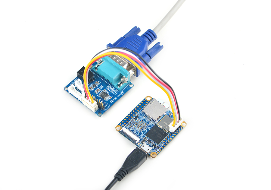
- If you want to do kernel development you need to use a serial communication board, ie a PSU-ONECOM board, which will allow you to operate the board via a serial terminal.Here is a setup where we connect a NanoPi NEO AIR to a PC via a serial cable you will see system messages output to the PC’s serial terminal:
- The password for both "root" and "fa" is "fa"
- Update software packages
apt-get update5.2 WiFi Connection
Insert a TF card with eflasher to a PC running Ubuntu and make the following changes in the etc/wpa_supplicant/wpa_supplicant.conf file under the rootfs section:
ctrl_interface=DIR=/var/run/wpa_supplicant GROUP=netdev
update_config=1
network={
        ssid="YOUR-WIFI-ESSID"
        psk="YOUR-WIFI-PASSWORD"
}
Note: the "YOUR-WIFI-ESSID" and "YOUR-WIFI-PASSWORD" need to be replaced with your actual ESSID and password.
Save, exit and insert the TF card to your AIR. After power on your AIR and the blue LED is blinking for one minute you will be able to check AIR's IP address.
5.3 SSH Login
The NanoPi NEO AIR has no display interface. If you don't have a serial communication board to connect your AIR to a PC you can log in your AIR via SSH. In our example the AIR's IP address was 192.168.1.230 and we logged in AIR by using the following command:
ssh root@192.168.1.230
The password is fa。
5.4 烧写系统到eMMC
eflasher系统内默认已经包含了一个Ubuntu-Core系统,运行TF卡中的eflasher系统,登录终端后执行以下命令将Ubuntu-core烧写到eMMC中:
flash_eMMC.sh -d /mnt/sdcard/Ubuntu-Core-qte/
该命令会将Ubuntu-Core烧写到eMMC,将WiFi的配置文件拷贝到eMMC的系统中,并扩展eMMC中系统的文件系统分区。 烧写成功后,可以看到下列信息:
INFO: flash system to eMMC success
断电,将TF卡拔出,重新上电就能运行eMMC中的系统了。当AIR插入TF卡时,默认会优先从TF卡启动,只有当TF卡启动失败时,才会尝试用eMMC启动系统。
6 Ubuntu-Core系统的使用
6.1 查看CPU工作温度
获取当前CPU的温度、运行频率等信息:
cpu_freq
6.2 连接DVP摄像头模块(CAM500B)
CAM500B是一款500万像素摄像头模块,以DVP并行信号输出,详细信息请参考Matirx-CAM500B。
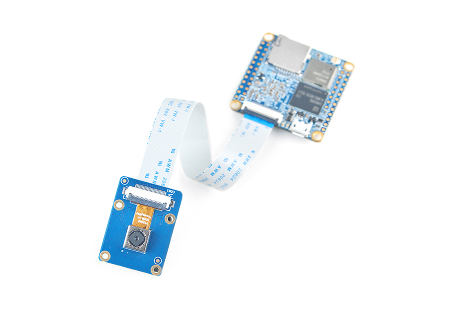
启动Debian系统,连接网络,以root用户登录终端并编译运行mjpg-streamer:
cd /root/mjpg-streamer
make
./start.sh
mjpg-streamer是一个开源的网络视频流服务器,在板子上成功运行mjpg-streamer后会打印下列信息:
 i: Using V4L2 device.: /dev/video0
 i: Desired Resolution: 1280 x 720
 i: Frames Per Second.: 30
 i: Format............: YUV
 i: JPEG Quality......: 90
 o: www-folder-path...: ./www/
 o: HTTP TCP port.....: 8080
 o: username:password.: disabled
 o: commands..........: enabled
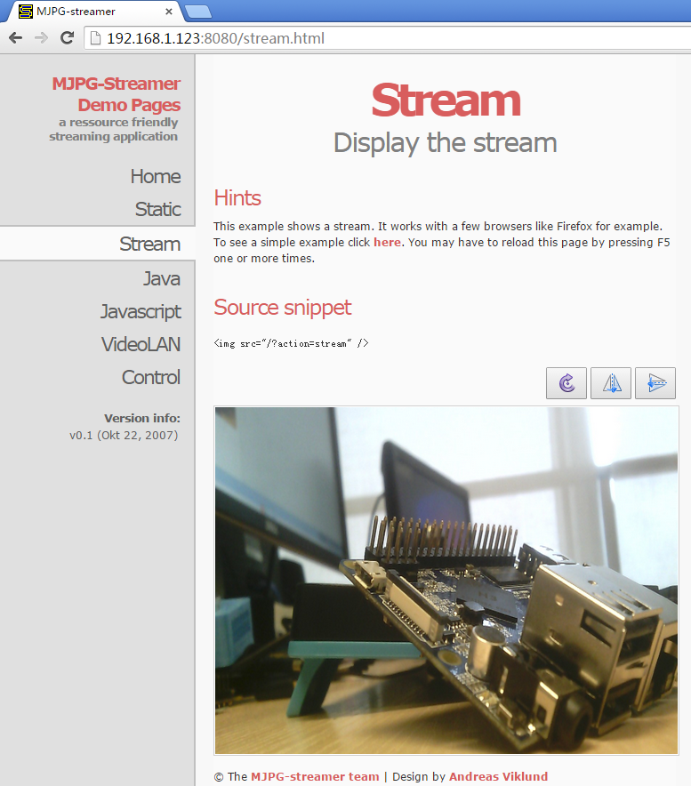
假设AIR的IP地址为192.168.1.230,在PC的浏览器中输入 192.168.1.230:8080 就能浏览摄像头采集的画面了,效果如下:
mjpg-streamer是用libjpeg对摄像头数据进行软编码,你可以使用ffmpeg对摄像头数据进行硬编码,这样能大大降低CPU的占用率并提高编码速度:
ffmpeg -t 30 -f v4l2 -channel 0 -video_size 1280x720 -i /dev/video0 -pix_fmt nv12 -r 30 -b:v 64k -c:v cedrus264 test.mp4
默认会录制30秒的视频,输入q能终止录制。录制完成后会在当前目录生成一个名为test.mp4的视频文件,可将其拷贝到PC上进行播放验证。
7 如何编译BSP
访问此处下载地址的sources目录,下载源码nanopi-H3-bsp。
使用7-Zip工具解压后得到两个目录:lichee和android,也可以从github上克隆lichee源码:
git clone https://github.com/friendlyarm/h3_lichee.git lichee
注:lichee是全志为其CPU的板级支持包所起的项目名称,里面包含了U-boot,Linux等源码和众多的编译脚本。
7.1 编译lichee源码
编译全志 H3 的BSP源码包必须使用64bit的Linux PC系统,并安装下列软件包,下列操作均基于Ubuntu-14.04 LTS-64bit:
sudo apt-get install gawk git gnupg flex bison gperf build-essential \
zip curl libc6-dev libncurses5-dev:i386 x11proto-core-dev \
libx11-dev:i386 libreadline6-dev:i386 libgl1-mesa-glx:i386 \
libgl1-mesa-dev g++-multilib mingw32 tofrodos \
python-markdown libxml2-utils xsltproc zlib1g-dev:i386 u-boot-tools
编译lichee源码包,进入lichee目录,执行命令:
cd lichee
./build.sh -p sun8iw7p1 -b nanopi-h3
该命令会一次性编译好U-boot、Linux内核和模块。
注:lichee目录里内置了交叉编译器,当使用build.sh脚本进行源码编译时,会自动使用该内置的编译器,所以无需手动安装编译器。
7.2 打包系统组件
./gen_script.sh nanopi-air该命令会将所有编译生成的可执行文件(包括U-boot、Linux内核)和系统配置文件拷贝到lichee/tools/pack/out/目录以便进行统一管理,并且会该目录下生成
script.bin文件。
script.bin是全志系列 CPU 的硬件板级配置文件,相关信息请查看script.bin。
下列命令可用于更新TF卡上的U-boot:
./fuse_uboot.sh /dev/sdx
/dev/sdx请替换为实际的TF卡设备文件名。
uImage和内核模块均位于linux-3.4/output目录下,将uImage拷贝到TF卡的boot分区的根目录即可更新内核。
7.3 编译U-boot
如果你想单独编译U-boot,可以执行命令:
./build.sh -p sun8iw7p1 -b nanopi-h3 -m uboot
编译生成的可执行文件需打上全志系列CPU的硬件板级配置补丁后才能烧写到TF卡上运行,执行./build.sh pack能自动完成打补丁的操作。
如何手动为U-boot打补丁请查看H3_Manual_build_howto,执行下列命令更新TF卡上的U-boot:
./fuse_uboot.sh /dev/sdx
/dev/sdx请替换为实际的TF卡设备文件名。
7.4 编译Linux内核
如果你想单独编译Linux内核,可以执行命令:
./build.sh -p sun8iw7p1 -b nanopi-h3 -m kernel
编译完成后uImage和内核模块均位于linux-3.4/output目录下,将uImage拷贝到TF卡的boot分区的根目录即可。
7.5 清理lichee源码
./build.sh -p sun8iw7p1_linux -b nanopi-h3 -m clean
8 3D 打印外壳
NanoPi NEO-AIR 3D printed housing
3D打印外壳下载链接
