Difference between revisions of "Matrix - Soil Moisture Sensor"
(→连接NanoPi M2 / NanoPi 2 Fire) |
(→Basic Device Operation工作原理) |
||
| (8 intermediate revisions by the same user not shown) | |||
| Line 1: | Line 1: | ||
[[Matrix - Soil Moisture Sensor/zh|查看中文]] | [[Matrix - Soil Moisture Sensor/zh|查看中文]] | ||
| − | == | + | ==Introduction== |
| − | [[File:Matrix - Soil_Moisture_Sensor.jpg|thumb| | + | [[File:Matrix - Soil_Moisture_Sensor.jpg|thumb|Soil Moisture Sensor Module]] |
| − | * | + | * The Matrix-Soil_Moisture_Sensor is a simple and straightforward-to-use soil moisture detection module. |
| − | * | + | * Before plug the module to a target soil make sure the target soil doesn’t contain rocks. Then point the pads perpendicular to the soil, push it in and make the module close contact to the soil and the module will output analog signals which are proportional to the soil’s moisture condition. |
| − | * | + | * To improve the test result it is suggested to take the average of multiple test results. |
| − | * | + | * The test result can be influenced by various factors: soil density, soil composition and etc. |
| − | == | + | ==Hardware Specification== |
| − | * | + | * Standard 3 PIN Interface |
| − | * | + | * PCB Dimension(mm): 20 x 60 |
| − | + | ||
[[File:Soil_Moisture_Sensor1.png | frameless|350px|Soil_Moisture_Sensor.PCB]] | [[File:Soil_Moisture_Sensor1.png | frameless|350px|Soil_Moisture_Sensor.PCB]] | ||
| − | * | + | * Pin Description: |
{| class="wikitable" | {| class="wikitable" | ||
|- | |- | ||
| − | | | + | |Pin || Description |
|- | |- | ||
|S || GPIO | |S || GPIO | ||
|- | |- | ||
| − | |V || | + | |V || Supply Voltage 5V |
|- | |- | ||
| − | |G || | + | |G || Ground |
|} | |} | ||
| − | == | + | ==Basic Device Operation== |
| − | * | + | * The resistance of the two pads(probes) is proportional to the moisture of surrounding environment. When the measured soil becomes increasingly drier the output voltage becomes lower and vice versa. The output analog signals of the module can be converted to digital signals (values of soil moisture) via AD conversion. |
| − | * | + | * It measures surrounding soil's apparent dielectric constant(ε) and calculates its moisture value(θv). |
| − | * | + | * This module uses adc inputs/outputs and converts analog signals to digital signals (moisture value) with PCF8591. |
| − | === | + | ==Applications== |
| − | + | ===Connect to NanoPi M1=== | |
| + | Refer to the following connection diagram to connect the module to the NanoPi M1:<br> | ||
[[File:Matrix-Soil_Moisture_Sensor_nanopi_m1.jpg|frameless|600px|Matrix-Soil_Moisture_Sensor_nanopi_m1]] | [[File:Matrix-Soil_Moisture_Sensor_nanopi_m1.jpg|frameless|600px|Matrix-Soil_Moisture_Sensor_nanopi_m1]] | ||
| − | + | Connection Details: | |
{| class="wikitable" | {| class="wikitable" | ||
|- | |- | ||
| Line 47: | Line 47: | ||
|} | |} | ||
| − | === | + | ===Connect to NanoPi 2=== |
| − | + | Refer to the following connection diagram to connect the module to the NanoPi 2:<br> | |
[[File:Matrix-Soil_Moisture_Sensor_nanopi_2.jpg|frameless|600px|Matrix-Soil_Moisture_Sensor_nanopi_2]] | [[File:Matrix-Soil_Moisture_Sensor_nanopi_2.jpg|frameless|600px|Matrix-Soil_Moisture_Sensor_nanopi_2]] | ||
| − | + | Connection Details: | |
{| class="wikitable" | {| class="wikitable" | ||
|- | |- | ||
| Line 63: | Line 63: | ||
|} | |} | ||
| − | === | + | ===Connect to NanoPi M2/NanoPi 2 Fire=== |
| − | NanoPi | + | Refer to the following connection diagram to connect the module to the NanoPi M2/ NanoPi 2 Fire:<br> |
| − | + | ||
[[File:Matrix-Soil_Moisture_Sensor_nanopi_m2.jpg|frameless|600px|Matrix-Soil_Moisture_Sensor_nanopi_m2]] | [[File:Matrix-Soil_Moisture_Sensor_nanopi_m2.jpg|frameless|600px|Matrix-Soil_Moisture_Sensor_nanopi_m2]] | ||
| − | + | Connection Details: | |
{| class="wikitable" | {| class="wikitable" | ||
|- | |- | ||
| Line 80: | Line 79: | ||
|} | |} | ||
| − | === | + | ===Connect to NanoPi M3=== |
| − | + | Refer to the following connection diagram to connect the module to the NanoPi M3:<br> | |
[[File:Matrix-Soil_Moisture_Sensor_nanopi_m3.jpg|frameless|600px|Matrix-Soil_Moisture_Sensor_nanopi_m3]] | [[File:Matrix-Soil_Moisture_Sensor_nanopi_m3.jpg|frameless|600px|Matrix-Soil_Moisture_Sensor_nanopi_m3]] | ||
| − | + | Connection Details: | |
{| class="wikitable" | {| class="wikitable" | ||
|- | |- | ||
| Line 96: | Line 95: | ||
|} | |} | ||
| − | === | + | ===Connect to NanoPC-T2=== |
| − | + | Refer to the following connection diagram to connect the module to the NanoPC-T2:<br> | |
[[File:Matrix-Soil_Moisture_Sensor_NanoPC-T2.jpg|frameless|600px|Matrix-Soil_Moisture_Sensor_NanoPC-T2]] | [[File:Matrix-Soil_Moisture_Sensor_NanoPC-T2.jpg|frameless|600px|Matrix-Soil_Moisture_Sensor_NanoPC-T2]] | ||
| − | + | Connection Details: | |
{| class="wikitable" | {| class="wikitable" | ||
|- | |- | ||
| Line 112: | Line 111: | ||
|} | |} | ||
| − | == | + | ==Compile & Run Test Program== |
| − | + | Boot your ARM board with Debian and copy the matrix code: | |
<syntaxhighlight lang="bash"> | <syntaxhighlight lang="bash"> | ||
$ apt-get update && apt-get install git | $ apt-get update && apt-get install git | ||
$ git clone https://github.com/friendlyarm/matrix.git | $ git clone https://github.com/friendlyarm/matrix.git | ||
</syntaxhighlight> | </syntaxhighlight> | ||
| − | + | If your cloning is done successfully a "matrix" directory will be generated. | |
| − | + | Compile and install Matrix: | |
<syntaxhighlight lang="bash"> | <syntaxhighlight lang="bash"> | ||
$ cd matrix | $ cd matrix | ||
| Line 126: | Line 125: | ||
</syntaxhighlight> | </syntaxhighlight> | ||
| − | + | Run test program: | |
<syntaxhighlight lang="bash"> | <syntaxhighlight lang="bash"> | ||
$ matrix-adc | $ matrix-adc | ||
</syntaxhighlight> | </syntaxhighlight> | ||
| − | + | Note: this module is not plug and play therefore before running the module please make sure it is connected to an ARM board.<br> | |
| − | + | Here is what you should observe:<br> | |
<syntaxhighlight lang="bash"> | <syntaxhighlight lang="bash"> | ||
The channel0 value is 2460 | The channel0 value is 2460 | ||
</syntaxhighlight> | </syntaxhighlight> | ||
| − | == | + | ==Code Sample== |
| − | + | This Matrix code sample can work with all the ARM boards mentioned in this module's wiki. The name of this code sample is "matrix-analog_to_digital_converter". Here is its source code: | |
<syntaxhighlight lang="c"> | <syntaxhighlight lang="c"> | ||
int main(int argc, char ** argv) | int main(int argc, char ** argv) | ||
| Line 166: | Line 165: | ||
} | } | ||
</syntaxhighlight> | </syntaxhighlight> | ||
| − | + | For more details about this APIs called in this code sample refer to [[Matrix API reference manual]] <br> | |
| − | == | + | ==Resources== |
| + | |||
| + | ==Update Log== | ||
| + | ===August-10-2016=== | ||
| + | * Created English wiki | ||
Latest revision as of 01:13, 10 August 2016
Contents
1 Introduction
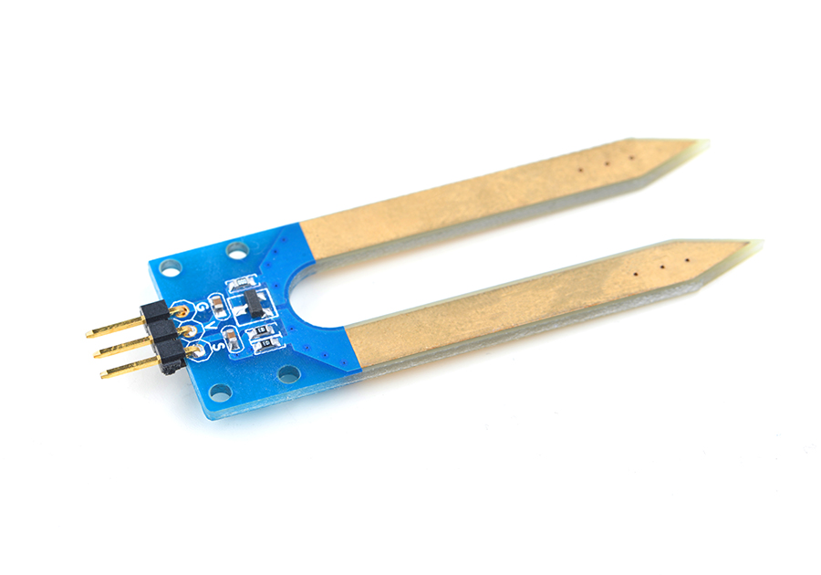
- The Matrix-Soil_Moisture_Sensor is a simple and straightforward-to-use soil moisture detection module.
- Before plug the module to a target soil make sure the target soil doesn’t contain rocks. Then point the pads perpendicular to the soil, push it in and make the module close contact to the soil and the module will output analog signals which are proportional to the soil’s moisture condition.
- To improve the test result it is suggested to take the average of multiple test results.
- The test result can be influenced by various factors: soil density, soil composition and etc.
2 Hardware Specification
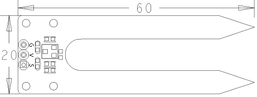
- Standard 3 PIN Interface
- PCB Dimension(mm): 20 x 60
- Pin Description:
| Pin | Description |
| S | GPIO |
| V | Supply Voltage 5V |
| G | Ground |
3 Basic Device Operation
- The resistance of the two pads(probes) is proportional to the moisture of surrounding environment. When the measured soil becomes increasingly drier the output voltage becomes lower and vice versa. The output analog signals of the module can be converted to digital signals (values of soil moisture) via AD conversion.
- It measures surrounding soil's apparent dielectric constant(ε) and calculates its moisture value(θv).
- This module uses adc inputs/outputs and converts analog signals to digital signals (moisture value) with PCF8591.
4 Applications
4.1 Connect to NanoPi M1
Refer to the following connection diagram to connect the module to the NanoPi M1:

Connection Details:
| Matrix-Soil_Moisture_Sensor | |
| GND | NanoPi M1 Pin9 |
| 5V | NanoPi M1 Pin2 |
| S | Matrix-Analog_to_Digital_Converter A0 |
4.2 Connect to NanoPi 2
Refer to the following connection diagram to connect the module to the NanoPi 2:

Connection Details:
| Matrix-Soil_Moisture_Sensor | |
| GND | NanoPi 2 Pin9 |
| 5V | NanoPi 2 Pin2 |
| S | Matrix-Analog_to_Digital_Converter A0 |
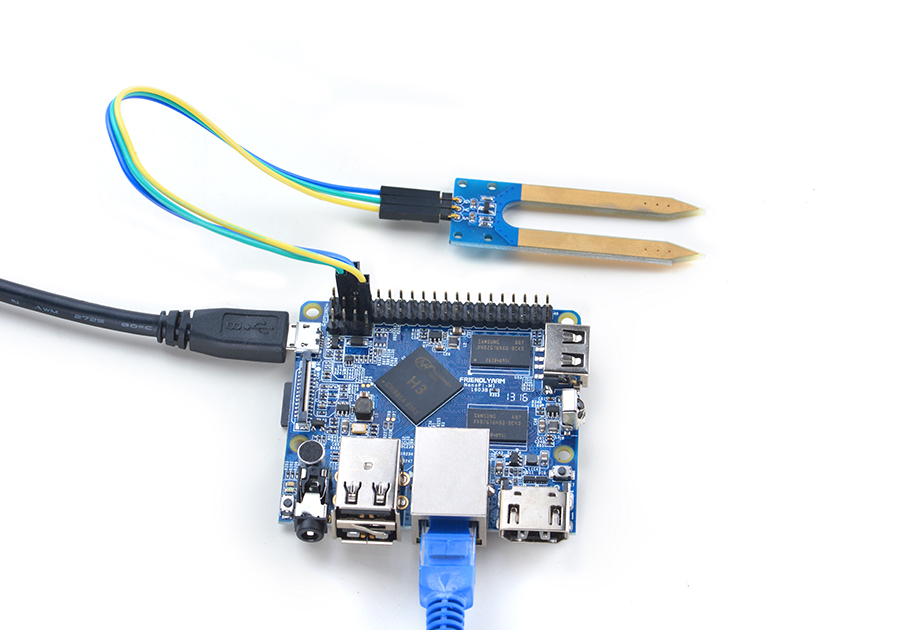
4.3 Connect to NanoPi M2/NanoPi 2 Fire
Refer to the following connection diagram to connect the module to the NanoPi M2/ NanoPi 2 Fire:
Matrix-Soil_Moisture_Sensor_nanopi_m2
Connection Details:
| Matrix-Soil_Moisture_Sensor | |
| GND | NanoPi M2 Pin9 |
| 5V | NanoPi M2 Pin2 |
| S | Matrix-Analog_to_Digital_Converter A0 |
4.4 Connect to NanoPi M3
Refer to the following connection diagram to connect the module to the NanoPi M3:
Matrix-Soil_Moisture_Sensor_nanopi_m3
Connection Details:
| Matrix-Soil_Moisture_Sensor | |
| GND | NanoPi M3 Pin9 |
| 5V | NanoPi M3 Pin2 |
| S | Matrix-Analog_to_Digital_Converter A0 |
4.5 Connect to NanoPC-T2
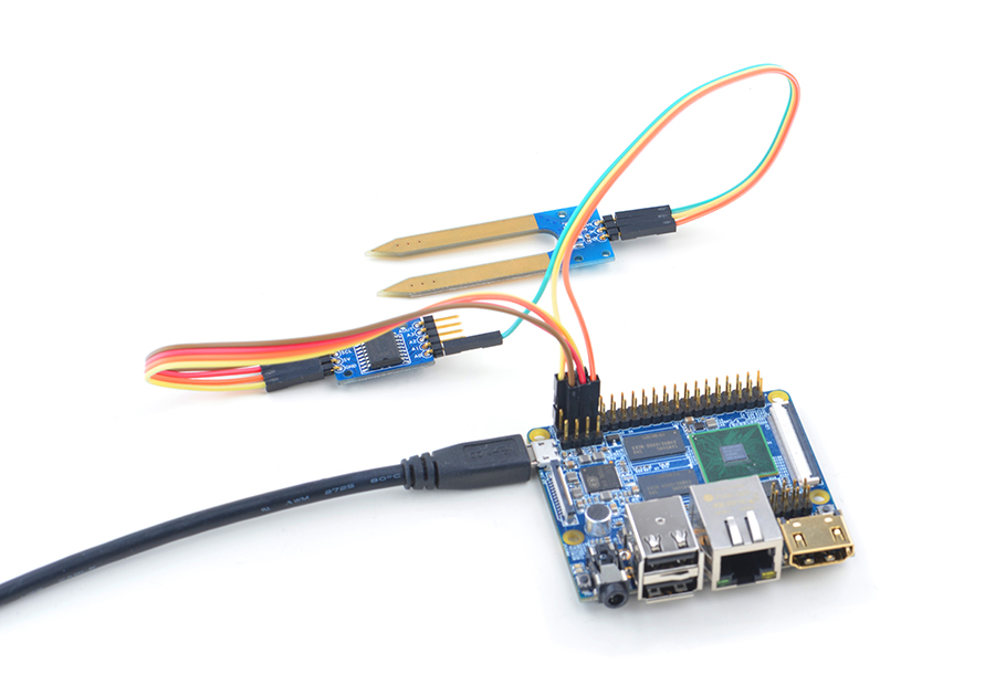
Refer to the following connection diagram to connect the module to the NanoPC-T2:
Matrix-Soil_Moisture_Sensor_NanoPC-T2
Connection Details:
| Matrix-Potentiometer | |
| GND | NanoPC-T2 USB Host GND |
| 5V | NanoPC-T2 USB Host 5V |
| S | Matrix-Analog_to_Digital_Converter A0 |
5 Compile & Run Test Program
Boot your ARM board with Debian and copy the matrix code:
$ apt-get update && apt-get install git
$ git clone https://github.com/friendlyarm/matrix.git
If your cloning is done successfully a "matrix" directory will be generated.
Compile and install Matrix:
$ cd matrix
$ make && make install
Run test program:
$ matrix-adcNote: this module is not plug and play therefore before running the module please make sure it is connected to an ARM board.
Here is what you should observe:
The channel0 value is 24606 Code Sample
This Matrix code sample can work with all the ARM boards mentioned in this module's wiki. The name of this code sample is "matrix-analog_to_digital_converter". Here is its source code:
int main(int argc, char ** argv)
{
    int i = 0;
    int value = 0;
    int channel = 0;

    if (boardInit() < 0) {
        printf("Fail to init board\n");
        return -1;
    }

    if (argc == 2)
        channel = atoi(argv[1]);
    system("modprobe "DRIVER_MODULE);
    signal(SIGINT, intHandler);
    for (i=0; i<ADC_READ_TIMES; i++) {
        if (pcf8591Read(channel, &value) != -1) {
            printf("The channel%d value is %d\n", channel, value);
        } else {
            printf("Fail to get channel%d value\n", channel);
        }
    }
    system("rmmod "DRIVER_MODULE);

    return 0;
}
For more details about this APIs called in this code sample refer to Matrix API reference manual
7 Resources
8 Update Log
8.1 August-10-2016
- Created English wiki

