Difference between revisions of "NanoPi NEO"
(→快速入门) |
(→Essentials You Need) |
||
| Line 112: | Line 112: | ||
===Essentials You Need=== | ===Essentials You Need=== | ||
Before starting to use your NanoPi NEO get the following items ready | Before starting to use your NanoPi NEO get the following items ready | ||
| − | * NanoPi | + | * NanoPi NEO |
* microSD Card/TFCard: Class 10 or Above, minimum 8GB SDHC | * microSD Card/TFCard: Class 10 or Above, minimum 8GB SDHC | ||
* microUSB power. A 5V/2A power is a must | * microUSB power. A 5V/2A power is a must | ||
Revision as of 08:54, 7 July 2016
Contents
1 Introduction
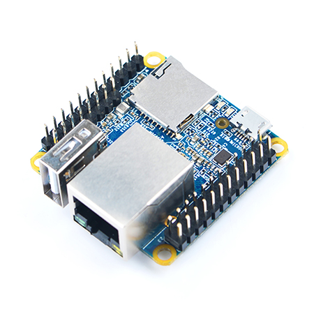
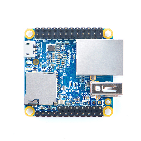
- The NanoPi NEO(abbreviated as NEO) is another fun board developed by FriendlyARM for makers, hobbyists and fans.
2 Features
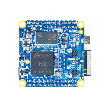
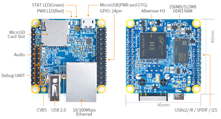
- CPU: Allwinner H3, Quad-core Cortex-A7 Up to 1.2GHz
- DDR3 RAM: 256MB/512MB
- Connectivity: 10/100M Ethernet
- USB Host: Type-A x 1, 2.54 mm pin x 2
- MicroSD Slot x 1
- MicroUSB: for data transmission and power input
- Debug Serial Port: 4Pin, 2.54 mm pitch pin header
- GPIO: 2.54mm pitch 36pin. It includes UART, SPI, I2C, IO etc
- PCB Dimension: 40 x 40 mm
- Power Supply: DC 5V/2A
- OS/Software: u-boot and UbuntuCore
3 Diagram, Layout and Dimension
3.1 Layout
- GPIO Pin Description
Pin# Name Linux gpio Pin# Name Linux gpio 1 SYS_3.3V 2 VDD_5V 3 I2C0_SDA 4 VDD_5V 5 I2C0_SCL 6 GND 7 GPIOG11 203 8 UART1_TX/GPIOG6 198 9 GND 10 UART1_RX/GPIOG7 199 11 UART2_TX/GPIOA0 0 12 PWM1/GPIOA6 6 13 UART2_RTS/GPIOA2 2 14 GND 15 UART2_CTS/GPIOA3 3 16 UART1_RTS/GPIOG8 200 17 SYS_3.3V 18 UART1_CTS/GPIOG9 201 19 SPI0_MOSI/GPIOC0 64 20 GND 21 SIP0_MISO/GPIOC1 65 22 UART2_RX/GPIOA1 1 23 SPI0_CLK/GPIOC29 93 24 SPI0_CS/GPIOC3 67
- USB/Audio/IR Pin Description
Pin# Name Description 1 VDD_5V 5V Power Out 2 USB-DP1 USB1 DP Signal 3 USB-DM1 USB1 DM Signal 4 USB-DP2 USB2 DP Signal 5 USB-DM2 USB2 DM Signal 6 GPIOL11/IR-RX GPIOL11 or IR Receive 7 SPDIF-OUT/GPIOA17 GPIOA17 or SPDIF-OUT 8 MICIN1P Microphone Positive Input 9 MICIN1N Microphone Negative Input 10 LINEOUTR LINE-OUT Right Channel Output 11 LINEOUTL LINE-OUT Left Channel Output 12 GND 0V
- Debug Port(UART0)
Pin# Name 1 GND 2 VDD_5V 3 UART_TXD0 4 UART_RXD0
- Note:
- SYS_3.3V: 3.3V power output
- VVDD_5V: 5V power input/output. When the external device’s power is greater than the MicroUSB's the external device is charging the board otherwise the board powers the external device. The input range is 4.7V ~ 5.6V
- All pins are 3.3V, output current is 5mA
- For more details refer to the document: NanoPi-NEO-1606-Schematic.pdf
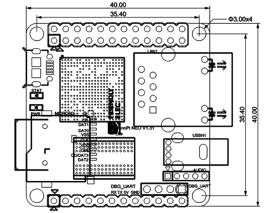
3.2 Dimensional Diagram
- For more details refer to the document: pcb file in dxf format
4 Get Started
4.1 Essentials You Need
Before starting to use your NanoPi NEO get the following items ready
- NanoPi NEO
- microSD Card/TFCard: Class 10 or Above, minimum 8GB SDHC
- microUSB power. A 5V/2A power is a must
- A Host computer running Ubuntu 14.04 64 bit system
4.2 TF Cards We Tested
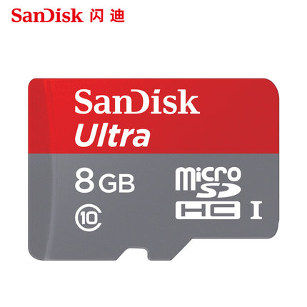
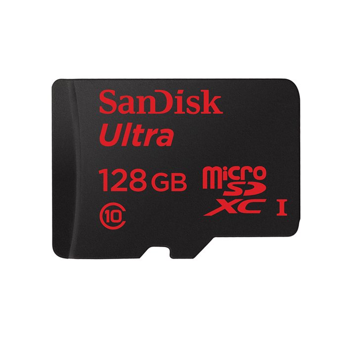
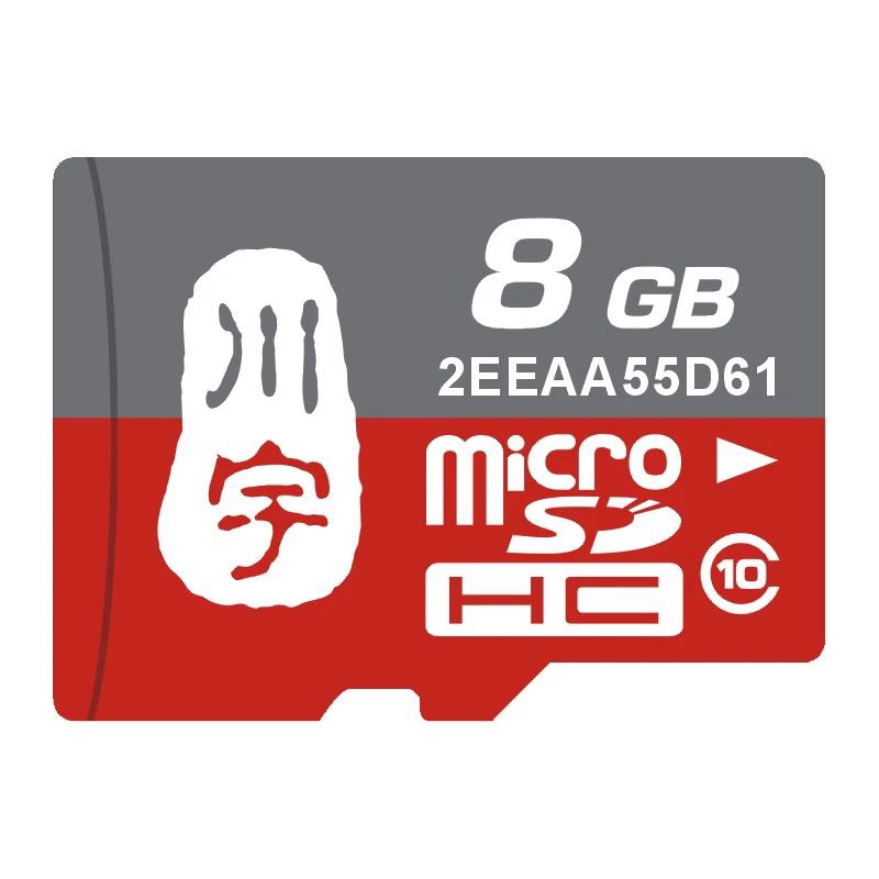
To make your NanoPi NEO boot and run fast we highly recommand you use a Class10 8GB SDHC TF card or a better one. The following cards are what we used in all our test cases presented here:
- SanDisk TF 8G Class10 Micro/SD TF card:
- SanDisk TF128G MicroSDXC TF 128G Class10 48MB/S:
- 川宇 8G C10 High Speed class10 micro SD card:
4.3 制作一张带运行系统的TF卡
4.3.1 下载系统固件
首先访问下载地址下载需要的固件文件(officail-ROMs目录)和烧写工具(tools目录):
使用以下固件: nanopi-neo-core-qte-sd4g.img.zip Ubuntu-Core with Qt-Embedded系统固件 烧写工具: win32diskimager.rar Windows平台下的系统烧写工具,Linux平台下可以用dd命令烧写系统
4.3.2 制作Ubuntu-Core with Qt-Embedded系统TF卡
将固件nanopi-neo-core-qte-sd4g.img.zip和烧写工具win32diskimager.rar分别解压,在Windows下插入TF卡(限4G及以上的卡),以管理员身份运行 win32diskimager 工具, 在win32diskimager工具的界面上,选择你的TF卡盘符,选择系统固件,点击 Write 按钮烧写即可。
5 Ubuntu-Core with Qt-Embedded系统的使用
5.1 运行Ubuntu-Core with Qt-Embedded系统
- 将制作好TF卡插入NanoPi NEO,使用USB供电(5V/2A),NanoPi NEO会上电自动开机,看到板上的蓝色LED闪烁,这说明系统已经开始启动了。
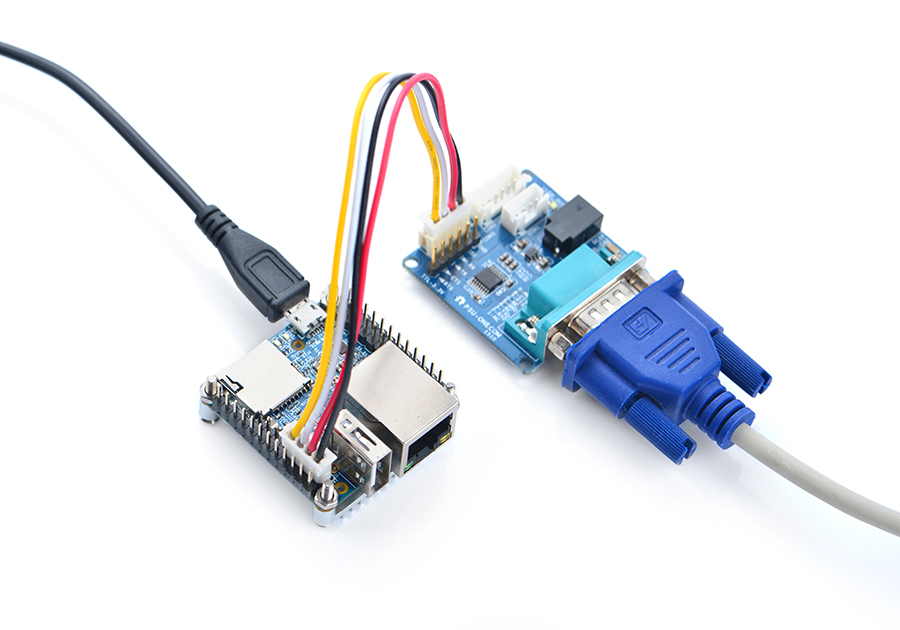
- 如果您需要进行内核开发,你最好选购一个串口配件,连接了串口,则可以通过串口终端对NanoPi NEO进行操作。以下是串口的接法,接上串口,即可调试。接上串口后你可以选择从串口模块的DC口或者从M1的MicroUSB口进行供电:
- 如果提示输入密码,Ubuntu-Core的root和fa用户的默认密码都是两个字母fa。
- 更新软件包:
sudo apt-get update
5.2 连接有线网络
NanoPi NEO在加电开机前如果已正确的连接网线,则系统启动时会自动获取IP地址,如果没有连接网线、没有DHCP服务或是其它网络问题,则会导致获取IP地址失败,同时系统启动会因此等待约15~60秒的时间。 手动获取IP地址
dhclient eth0
5.3 SSH登录NEO
NEO没有任何图形界面输出的接口,如果你没有串口模块,可以通过SSH协议登录NEO。假设通过路由器查看到NEO的IP地址为192.168.1.230,你可以在PC机上执行如下命令登录NEO:
ssh root@192.168.1.230
密码为fa。
5.4 扩展TF卡文件系统
强烈建议做好系统运行卡之后立即进行文件系统 rootfs 分区的扩展,这将大大提升系统的性能,避免空间不足带来的各种繁琐问题。
- 方法1: 在PC机上扩展TF卡的文件系统 rootfs 分区:
sudo umount /dev/sdx?
sudo parted /dev/sdx unit % resizepart 2 100 unit MB print
sudo resize2fs -f /dev/sdx2
/dev/sdx请替换为实际的TF卡设备文件名。
- 方法2: 在NEO上扩展TF卡的文件系统 rootfs 分区,在NEO上运行Ubuntu-Core,然后执行命令:
sudo fs_resize根据提示,输入 y 开始扩展文件系统,然后再输入 y 选择重启NEO。重启后执行下列命令查看新分区大小:
df -h
5.5 连接USB WiFi
系统默认已经支持市面上众多常见的USB WiFi,想知道你的USB WiFi是否可用只需将其接在NEO上即可,已测试过的USB WiFi型号如下:
序号 型号 1 RTL8188CUS/8188EU 802.11n WLAN Adapter 2 RT2070 Wireless Adapter 3 RT2870/RT3070 Wireless Adapter 4 RTL8192CU Wireless Adapter 5 小米WiFi mt7601
5.6 查看CPU工作温度
获取当前CPU的温度、运行频率等信息:
cpu_freq
6 如何编译Ubuntu-Core with Qt-Embedded系统
访问此处下载地址的sources目录,下载源码nanopi-H3-bsp。
使用7-Zip工具解压后得到两个目录:lichee和android,也可以从github上克隆lichee源码:
git clone https://github.com/friendlyarm/h3_lichee.git lichee
注:lichee是全志为其CPU的板级支持包所起的项目名称,里面包含了U-boot,Linux等源码和众多的编译脚本。
6.1 编译lichee源码
编译全志 H3 的BSP源码包必须使用64bit的Linux PC系统,并安装下列软件包,下列操作均基于Ubuntu-14.04 LTS-64bit:
sudo apt-get install gawk git gnupg flex bison gperf build-essential \
zip curl libc6-dev libncurses5-dev:i386 x11proto-core-dev \
libx11-dev:i386 libreadline6-dev:i386 libgl1-mesa-glx:i386 \
libgl1-mesa-dev g++-multilib mingw32 tofrodos \
python-markdown libxml2-utils xsltproc zlib1g-dev:i386
编译lichee源码包,进入lichee目录,执行命令:
cd lichee
./build.sh -p sun8iw7p1 -b nanopi-h3
该命令会一次性编译好U-boot、Linux内核和模块。
注:lichee目录里内置了交叉编译器,当使用build.sh脚本进行源码编译时,会自动使用该内置的编译器,所以无需手动安装编译器。
6.2 打包系统组件
./gen_script.sh nanopi-neo该命令会将所有编译生成的可执行文件(包括U-boot、Linux内核)和系统配置文件拷贝到lichee/tools/pack/out/目录以便进行统一管理,并且会该目录下生成
script.bin文件。
script.bin是全志系列 CPU 的硬件板级配置文件,相关信息请查看script.bin。
下列命令可用于更新TF卡上的U-boot:
./fuse_uboot.sh /dev/sdx
/dev/sdx请替换为实际的TF卡设备文件名。
uImage和内核模块均位于linux-3.4/output目录下,将uImage拷贝到TF卡的boot分区的根目录即可更新内核。
6.3 编译U-boot
如果你想单独编译U-boot,可以执行命令:
./build.sh -p sun8iw7p1 -b nanopi-h3 -m uboot
编译生成的可执行文件需打上全志系列CPU的硬件板级配置补丁后才能烧写到TF卡上运行,执行./build.sh pack能自动完成打补丁的操作。
如何手动为U-boot打补丁请查看H3_Manual_build_howto,执行下列命令更新TF卡上的U-boot:
./fuse_uboot.sh /dev/sdx
/dev/sdx请替换为实际的TF卡设备文件名。
6.4 编译Linux内核
如果你想单独编译Linux内核,可以执行命令:
./build.sh -p sun8iw7p1 -b nanopi-h3 -m kernel
编译完成后uImage和内核模块均位于linux-3.4/output目录下,将uImage拷贝到TF卡的boot分区的根目录即可。
6.5 清理lichee源码
./build.sh -p sun8iw7p1_linux -b nanopi-h3 -m clean
7 Resources
- Schematics
- Dimensional Diagram
- H3 Datesheet Allwinner_H3_Datasheet_V1.2.pdf
