Difference between revisions of "Matrix - RTC"
(→Introduction) |
(→Features) |
||
| Line 7: | Line 7: | ||
==Features== | ==Features== | ||
| − | * | + | * I2C serial interface |
| − | * | + | * 56-byte nonvolatile RAM |
| − | * 8-Pin | + | * 8-Pin DIP and 8-Pin SO |
| − | * | + | * Working temperature: -40 degree Celsius to 85 degree Celsius |
| − | * | + | * PCB dimension(mm): 24 x 32 |
[[File:Matrix-RTC_PCB.png|frameless|400px|]] | [[File:Matrix-RTC_PCB.png|frameless|400px|]] | ||
Latest revision as of 00:28, 24 June 2016
Contents
1 Introduction
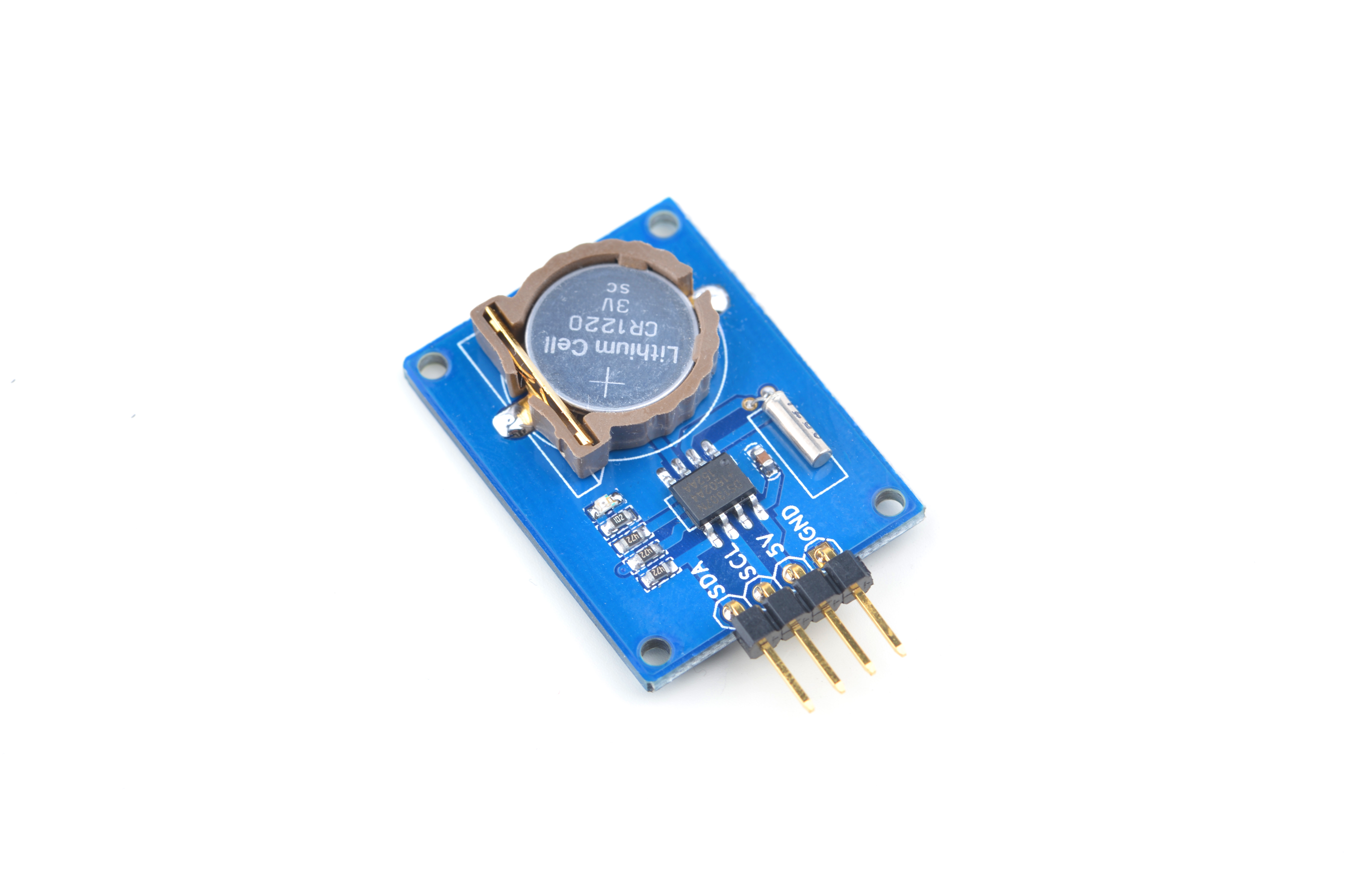
- The Matrix RTC module is a real time clock module. It uses the low power consumption chip DS1307 with valid up to 2100 56 byte nonvolatile RAM for data storage and 2-wire IIC serial interface
- It counts seconds, minutes, hours, date of the month, month, day of the week, and year with leap year compensation.
2 Features
- I2C serial interface
- 56-byte nonvolatile RAM
- 8-Pin DIP and 8-Pin SO
- Working temperature: -40 degree Celsius to 85 degree Celsius
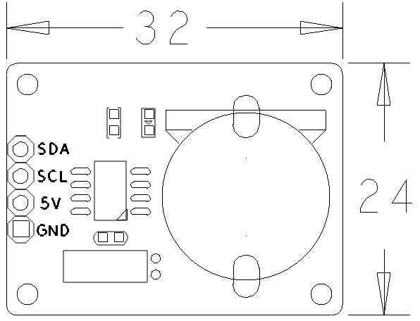
- PCB dimension(mm): 24 x 32
- Pin Description:
| Pin | Description |
| SDA | I2C SDA |
| SCL | I2C SCL |
| 5V | Supply Voltage 5V |
| GND | Ground |
3 Basic Device Operation
4 Applications
4.1 Connect to NanoPi M1
Refer to the following connection diagram to connect the module to the NanoPi M1:
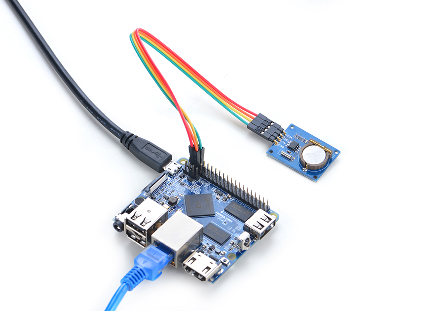
Connection Details:
| Matrix-RTC | NanoPi M1 |
| SDA | Pin3 |
| SCL | Pin5 |
| 5V | Pin4 |
| GND | Pin6 |
4.2 Connect to NanoPi 2
Refer to the following connection diagram to connect the module to the NanoPi 2:
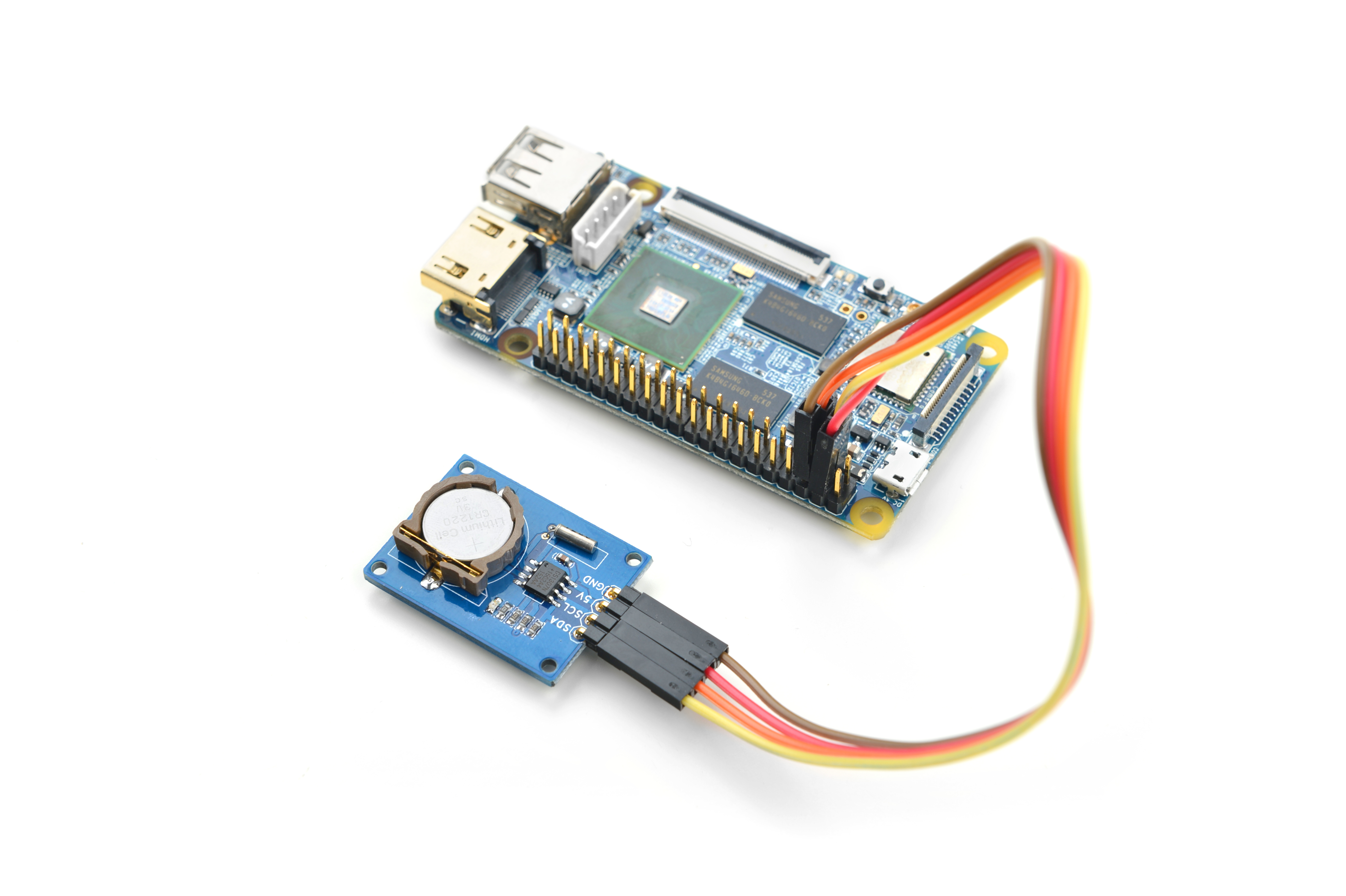
Connection Details:
| Matrix-RTC | NanoPi 2 |
| SDA | Pin3 |
| SCL | Pin5 |
| 5V | Pin4 |
| GND | Pin6 |
4.3 Connect to NanoPi M2 / NanoPi 2 Fire
Refer to the following connection diagram to connect the module to the NanoPi M2/ NanoPi 2 Fire:
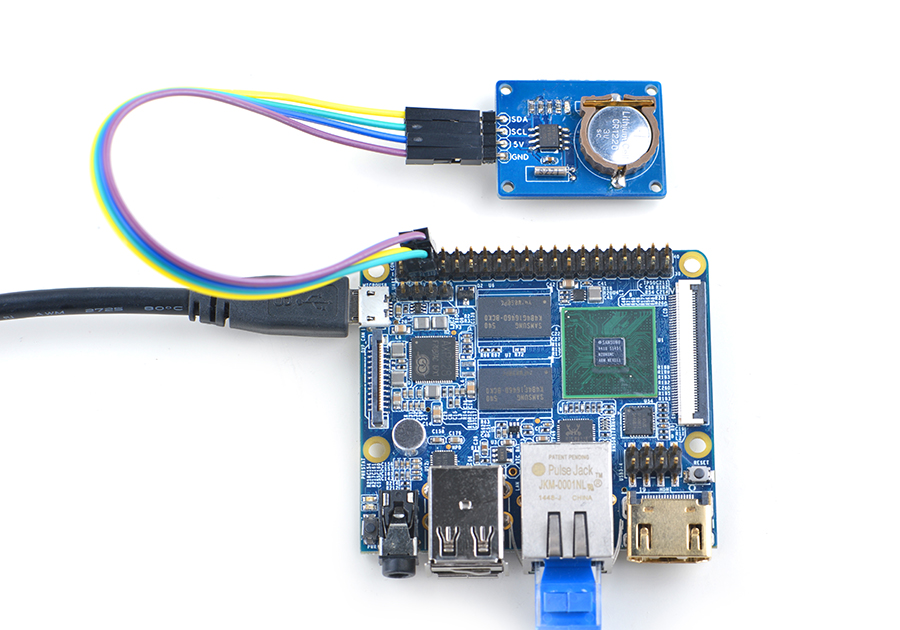
Connection Details:
| NanoPi M2 | |
| SDA | Pin3 |
| SCL | Pin5 |
| 5V | Pin4 |
| GND | Pin6 |
4.4 Connect to NanoPC-T2
Refer to the following connection diagram to connect the module to the NanoPC-T2:
Matrix-RTC_NanoPC-T2
Connection Details:
| Matrix-RTC | NanoPC-T2 |
| SDA | Pin6 |
| SCL | Pin5 |
| 5V | Pin29 |
| GND | Pin30 |
5 Compile & Run Test Program
Boot your ARM board with Debian and copy the matrix code:
$ apt-get update && apt-get install git
$ git clone https://github.com/friendlyarm/matrix.git
If your cloning is done successfully a "matrix" directory will be generated.
Compile and install Matrix:
$ cd matrix
$ make && make install
Run test program:
$ matrix-rtcNote: this module is not plug and play therefore before running the module please make sure it is connected to an ARM board.
Here is what you should observe:
RTC Driver Test Example.
Set RTC date/time is 9-15-2015, 01:01:01.
Read RTC date/time is 9-15-2015, 01:01:01.
Test complete
This program reads date/time from and writes date/time to the RTC module. If you want to set the date/time and save it in the RTC module under Debian you can try the following commands. For example if you want to set the date to "2016-11-17 17:26:01" and save it in the RTC module you can do it this way:
$ modprobe rtc-ds1307
$ date -s "2016-11-17 17:26:01"
$ hwclock -w -f /dev/rtc-ds1307
Open the /etc/modprobe.d/matrix-blacklist.conf file and add a "#" in front of "blacklist rtc_ds1307" to comment this line. After you reboot your board the changed date/time will be effective
$ hwclock -r -f /dev/rtc-ds1307
2016 11 18 Friday 08:29:48  -0.492649 seconds
6 Code Sample
This Matrix code sample can work with all the ARM boards mentioned in this module's wiki. The name of this code sample is "matrix-rtc". Here is its source code:
int main(int argc, char **argv)
{
    int fd, retval, board;
    struct rtc_time rtc_tm;
    const char *rtc = default_rtc;
    const char *date_time = default_date_time;

    if ((board = boardInit()) < 0) {
        printf("Fail to init board\n");
        return -1;
    }

    switch (argc) {
    case 3:
        rtc = argv[1];
        date_time = argv[2];
        break;
    case 1:
        break;
    default:
        fprintf(stderr, "usage:  rtctest [rtcdev] [year mon day hour min sec]\n");
        return 1;
    }
    system("modprobe "DRIVER_MODULE);
    fd = open(rtc, O_RDONLY);
    if (fd ==  -1) {
        perror(rtc);
        goto err;
    }
    fprintf(stderr, "RTC Driver Test Example.\n");

    sscanf(date_time, "%d %d %d %d %d %d",
            &rtc_tm.tm_year,
            &rtc_tm.tm_mon,
            &rtc_tm.tm_mday,
            &rtc_tm.tm_hour,
            &rtc_tm.tm_min,
            &rtc_tm.tm_sec);
    rtc_tm.tm_year -= 1900;
    rtc_tm.tm_mon -= 1;
    retval = ioctl(fd, RTC_SET_TIME, &rtc_tm);
    if (retval == -1) {
        perror("RTC_SET_TIME ioctl");
        goto err;
    }

    fprintf(stderr, "Set RTC date/time is %d-%d-%d, %02d:%02d:%02d.\n",
            rtc_tm.tm_mon + 1, rtc_tm.tm_mday, rtc_tm.tm_year + 1900,
            rtc_tm.tm_hour, rtc_tm.tm_min, rtc_tm.tm_sec);

    /* Read the RTC time/date */
    retval = ioctl(fd, RTC_RD_TIME, &rtc_tm);
    if (retval == -1) {
        perror("RTC_RD_TIME ioctl");
        goto err;
    }

    fprintf(stderr, "Read RTC date/time is %d-%d-%d, %02d:%02d:%02d.\n",
            rtc_tm.tm_mon + 1, rtc_tm.tm_mday, rtc_tm.tm_year + 1900,
            rtc_tm.tm_hour, rtc_tm.tm_min, rtc_tm.tm_sec);

    fprintf(stderr, "Test complete\n");
    close(fd);
err:
    system("rmmod "DRIVER_MODULE);
    return 0;
}
For more details about this APIs called in this code sample refer to Matrix API reference manual
7 Resources
8 Update Log
8.1 June-24-2016
- Created English wiki
