Difference between revisions of "Matrix - One Touch Sensor"
(→Basic Device Operation) |
|||
| (20 intermediate revisions by 2 users not shown) | |||
| Line 1: | Line 1: | ||
| − | [[Matrix - One Touch Sensor| | + | [[Matrix - One Touch Sensor/zh|查看中文]] |
| − | == | + | |
| + | ==Introduction== | ||
[[File:Matrix-One_Touch_Sensor.png|thumb|]] | [[File:Matrix-One_Touch_Sensor.png|thumb|]] | ||
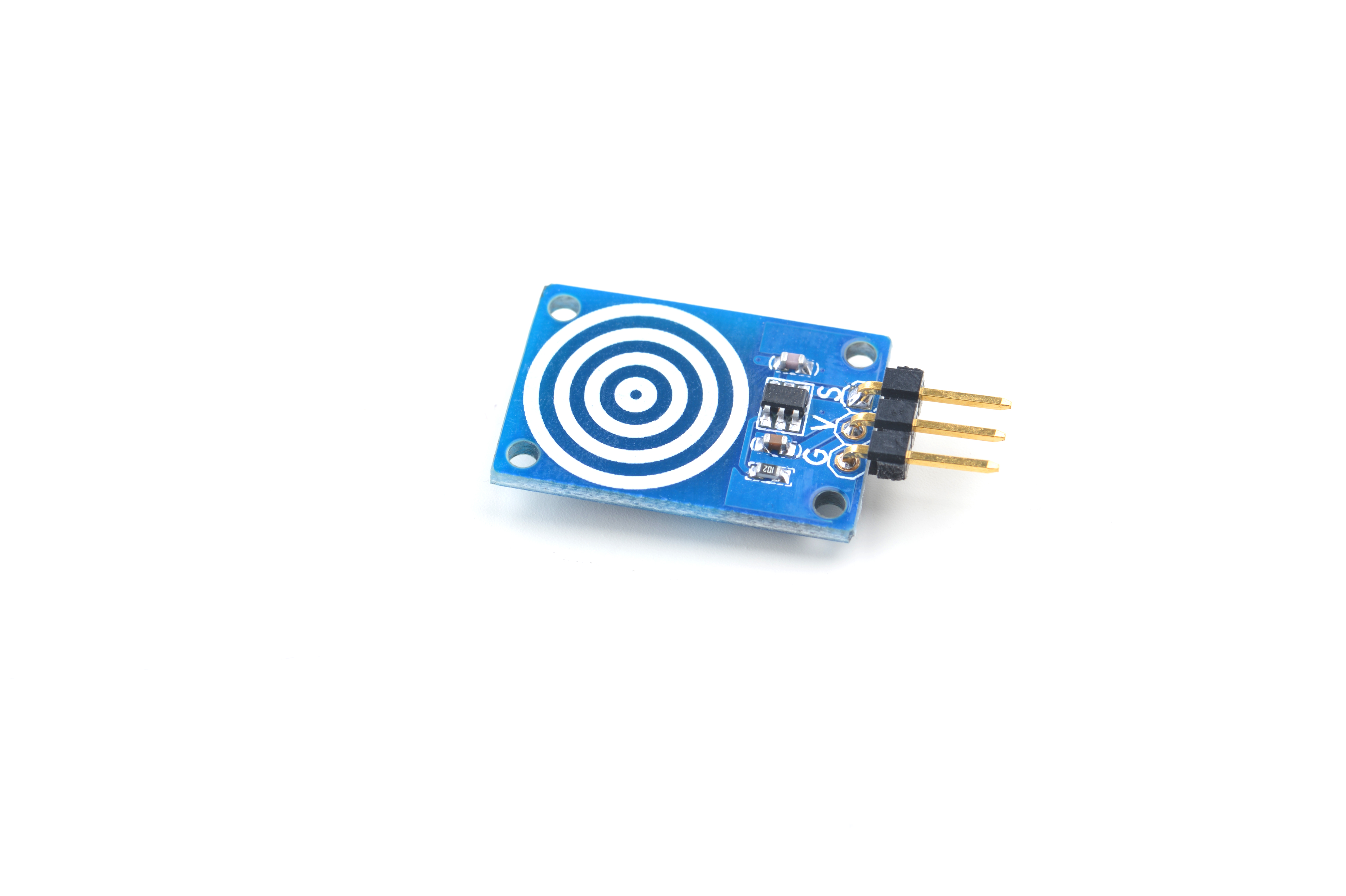
| − | * | + | * The Matrix One_Touch_Sensor is a digital one capacitive touch key module. It uses the one key capacitive touch pad detector IC TTP223. It has a touch key with stable touching detection. It is designed for replacing traditional direct button key with diverse pad size.By default it outputs low. When a finger touches the touch key it outputs high. |
| − | == | + | |
| − | * | + | ==Features== |
| − | + | * Standard 3Pin interface | |
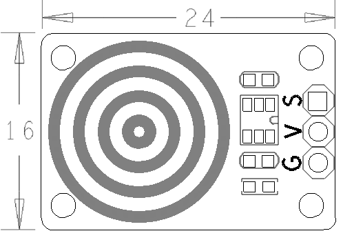
| − | + | * PCB dimension(mm): 16 x 24 | |
| − | * | + | |
[[File:Matrix-One_Touch_Sensor_PCB.png|frameless|400px|]] | [[File:Matrix-One_Touch_Sensor_PCB.png|frameless|400px|]] | ||
| − | * | + | * Pin Description: |
{| class="wikitable" | {| class="wikitable" | ||
|- | |- | ||
| − | | | + | |Pin || Description |
|- | |- | ||
| − | | | + | |S || GPIO |
| + | |- | ||
| + | |V || Supply Voltage 5V | ||
|- | |- | ||
| − | | | + | |G || Ground |
| + | |} | ||
| + | |||
| + | ==Basic Device Operation== | ||
| + | The TTP223 is a one key capacitive touch pad detector IC. It measures changes of electric charges stored in the touch pad electrode with parasitic capacitance. The touch pad is usually attached to an insulator:acrylic, glass, porcelain, wood and etc. | ||
| + | |||
| + | ==Applications== | ||
| + | ===Connect to NanoPi M1=== | ||
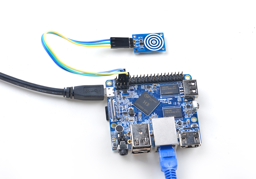
| + | Refer to the following connection diagram to connect the module to the NanoPi M1:<br> | ||
| + | [[File:Matrix-One_Touch_Sensor_nanopi_m1.jpg|frameless|600px|Matrix-One_Touch_Sensor_nanopi_m1]] | ||
| + | |||
| + | Connection Details: | ||
| + | {| class="wikitable" | ||
| + | |- | ||
| + | |Matrix-One_Touch_Sensor || NanoPi M1 | ||
| + | |- | ||
| + | |S || Pin7 | ||
| + | |- | ||
| + | |V || Pin4 | ||
|- | |- | ||
| − | | | + | |G || Pin6 |
| + | |} | ||
| + | |||
| + | ===Connect to NanoPi 2=== | ||
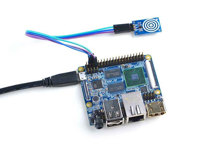
| + | Refer to the following connection diagram to connect the module to the NanoPi 2:<br> | ||
| + | [[File:Matrix-One_Touch_Sensor_nanopi_2.jpg|frameless|600px|Matrix-One_Touch_Sensor_nanopi_2]] | ||
| + | |||
| + | Connection Details: | ||
| + | {| class="wikitable" | ||
|- | |- | ||
| − | | | + | |Matrix-One_Touch_Sensor || NanoPi 2 |
| + | |- | ||
| + | |S || Pin7 | ||
| + | |- | ||
| + | |V || Pin4 | ||
| + | |- | ||
| + | |G || Pin6 | ||
|} | |} | ||
| − | == | + | ===Connect to NanoPi M2 / NanoPi 2 Fire=== |
| + | Refer to the following connection diagram to connect the module to the NanoPi M2/ NanoPi 2 Fire.<br> | ||
| + | [[File:Matrix-One_Touch_Sensor_nanopi_m2.jpg|frameless|600px|Matrix-One_Touch_Sensor_nanopi_m2]] | ||
| + | |||
| + | Connection Details: | ||
| + | {| class="wikitable" | ||
| + | |- | ||
| + | |Matrix-One_Touch_Sensor || NanoPi M2 | ||
| + | |- | ||
| + | |S || Pin7 | ||
| + | |- | ||
| + | |V || Pin4 | ||
| + | |- | ||
| + | |G || Pin6 | ||
| + | |} | ||
| + | |||
| + | ===Connect to NanoPC-T2=== | ||
| + | Refer to the following connection diagram to connect the module to the NanoPC-T2:<br> | ||
| + | [[File:Matrix-One_Touch_Sensor_NanoPC-T2.jpg|frameless|600px|Matrix-One_Touch_Sensor_NanoPC-T2]] | ||
| + | |||
| + | Connection Details: | ||
| + | {| class="wikitable" | ||
| + | |- | ||
| + | |Matrix-One_Touch_Sensor || NanoPC-T2 | ||
| + | |- | ||
| + | |S || Pin15 | ||
| + | |- | ||
| + | |V || Pin29 | ||
| + | |- | ||
| + | |G || Pin30 | ||
| + | |} | ||
| + | |||
| + | ==Compile & Run Test Program== | ||
| + | Boot your ARM board with Debian and copy the matrix code: | ||
| + | <syntaxhighlight lang="bash"> | ||
| + | $ apt-get update && apt-get install git | ||
| + | $ git clone https://github.com/friendlyarm/matrix.git | ||
| + | </syntaxhighlight> | ||
| + | If your cloning is done successfully a "matrix" directory will be generated. | ||
| + | |||
| + | Compile and install Matrix: | ||
| + | <syntaxhighlight lang="bash"> | ||
| + | $ cd matrix | ||
| + | $ make && make install | ||
| + | </syntaxhighlight> | ||
| + | |||
| + | Run test program: | ||
| + | <syntaxhighlight lang="bash"> | ||
| + | $ matrix-gpio_int | ||
| + | </syntaxhighlight> | ||
| + | Note: this module is not plug and play therefore before running the module please make sure it is connected to an ARM board.<br> | ||
| + | Here is what you should observe:<br> | ||
| + | <syntaxhighlight lang="bash"> | ||
| + | Waiting event... | ||
| + | Device[0] value is 1 | ||
| + | </syntaxhighlight> | ||
| + | When you touch the module's active area an event will be triggered and detected. | ||
| + | |||
| + | ==Code Sample== | ||
| + | This Matrix code sample can work with all the ARM boards mentioned in this module's wiki. The name of this code sample is "matrix-gpio_int". Here is its source code: | ||
| + | <syntaxhighlight lang="c"> | ||
| + | int main(int argc, char ** argv) | ||
| + | { | ||
| + | int i, board; | ||
| + | int retSize = -1; | ||
| + | char value[ARRAY_SIZE(dev)]; | ||
| + | |||
| + | if ((board = boardInit()) < 0) { | ||
| + | printf("Fail to init board\n"); | ||
| + | return -1; | ||
| + | } | ||
| + | |||
| + | if (argc == 2) | ||
| + | dev[0].pin = atoi(argv[1]); | ||
| + | system("modprobe "DRIVER_MODULE); | ||
| + | signal(SIGINT, intHandler); | ||
| + | if (board == BOARD_NANOPI_T2) | ||
| + | dev[0].pin = GPIO_PIN(15); | ||
| + | printf("Use GPIO_PIN(%d)\n", dev[0].pin); | ||
| + | if ((devFD =sensorInit(dev, ARRAY_SIZE(dev))) == -1) { | ||
| + | printf("Fail to init sensor\n"); | ||
| + | goto err; | ||
| + | } | ||
| + | printf("Waiting event...\n"); | ||
| + | if ((retSize = sensorRead(devFD, value, ARRAY_SIZE(dev))) == -1) { | ||
| + | printf("Fail to read sensors\n"); | ||
| + | } | ||
| + | if (retSize > 0) { | ||
| + | i = 0; | ||
| + | for (i=0; i<retSize; i++) { | ||
| + | printf("Device[%d] value is %d\n", i, value[i]); | ||
| + | } | ||
| + | } | ||
| + | sensorDeinit(devFD); | ||
| + | err: | ||
| + | system("rmmod "DRIVER_MODULE); | ||
| + | return 0; | ||
| + | } | ||
| + | </syntaxhighlight> | ||
| + | For more details about this APIs called in this code sample refer to [[Matrix API reference manual]] <br> | ||
| + | |||
| + | ==Resources== | ||
| + | |||
| + | ==Update Log== | ||
| + | ===June-22-2016=== | ||
| + | * Created English wiki | ||
Latest revision as of 00:10, 22 June 2016
Contents
1 Introduction
- The Matrix One_Touch_Sensor is a digital one capacitive touch key module. It uses the one key capacitive touch pad detector IC TTP223. It has a touch key with stable touching detection. It is designed for replacing traditional direct button key with diverse pad size.By default it outputs low. When a finger touches the touch key it outputs high.
2 Features
- Standard 3Pin interface
- PCB dimension(mm): 16 x 24
- Pin Description:
| Pin | Description |
| S | GPIO |
| V | Supply Voltage 5V |
| G | Ground |
3 Basic Device Operation
The TTP223 is a one key capacitive touch pad detector IC. It measures changes of electric charges stored in the touch pad electrode with parasitic capacitance. The touch pad is usually attached to an insulator:acrylic, glass, porcelain, wood and etc.
4 Applications
4.1 Connect to NanoPi M1
Refer to the following connection diagram to connect the module to the NanoPi M1:

Connection Details:
| Matrix-One_Touch_Sensor | NanoPi M1 |
| S | Pin7 |
| V | Pin4 |
| G | Pin6 |
4.2 Connect to NanoPi 2
Refer to the following connection diagram to connect the module to the NanoPi 2:
Matrix-One_Touch_Sensor_nanopi_2
Connection Details:
| Matrix-One_Touch_Sensor | NanoPi 2 |
| S | Pin7 |
| V | Pin4 |
| G | Pin6 |
4.3 Connect to NanoPi M2 / NanoPi 2 Fire
Refer to the following connection diagram to connect the module to the NanoPi M2/ NanoPi 2 Fire.

Connection Details:
| Matrix-One_Touch_Sensor | NanoPi M2 |
| S | Pin7 |
| V | Pin4 |
| G | Pin6 |
4.4 Connect to NanoPC-T2
Refer to the following connection diagram to connect the module to the NanoPC-T2:
Matrix-One_Touch_Sensor_NanoPC-T2
Connection Details:
| Matrix-One_Touch_Sensor | NanoPC-T2 |
| S | Pin15 |
| V | Pin29 |
| G | Pin30 |
5 Compile & Run Test Program
Boot your ARM board with Debian and copy the matrix code:
$ apt-get update && apt-get install git
$ git clone https://github.com/friendlyarm/matrix.git
If your cloning is done successfully a "matrix" directory will be generated.
Compile and install Matrix:
$ cd matrix
$ make && make install
Run test program:
$ matrix-gpio_intNote: this module is not plug and play therefore before running the module please make sure it is connected to an ARM board.
Here is what you should observe:
Waiting event...
Device[0] value is 1
When you touch the module's active area an event will be triggered and detected.
6 Code Sample
This Matrix code sample can work with all the ARM boards mentioned in this module's wiki. The name of this code sample is "matrix-gpio_int". Here is its source code:
int main(int argc, char ** argv)
{
    int i, board;
    int retSize = -1;
    char value[ARRAY_SIZE(dev)];

    if ((board = boardInit()) < 0) {
        printf("Fail to init board\n");
        return -1;
    }

    if (argc == 2)
        dev[0].pin = atoi(argv[1]);
    system("modprobe "DRIVER_MODULE);
    signal(SIGINT, intHandler);
    if (board == BOARD_NANOPI_T2)
        dev[0].pin = GPIO_PIN(15);
    printf("Use GPIO_PIN(%d)\n", dev[0].pin);
    if ((devFD =sensorInit(dev, ARRAY_SIZE(dev))) == -1) {
        printf("Fail to init sensor\n");
        goto err;
    }
    printf("Waiting event...\n");
    if ((retSize = sensorRead(devFD, value, ARRAY_SIZE(dev))) == -1) {
        printf("Fail to read sensors\n");
    }
    if (retSize > 0) {
        i = 0;
        for (i=0; i<retSize; i++) {
            printf("Device[%d] value is %d\n", i, value[i]);
        }
    }
    sensorDeinit(devFD);
err:
    system("rmmod "DRIVER_MODULE);
    return 0;
}
For more details about this APIs called in this code sample refer to Matrix API reference manual
7 Resources
8 Update Log
8.1 June-22-2016
- Created English wiki

