Difference between revisions of "NanoPi M1"
From FriendlyELEC WiKi
(→介绍) |
|||
| Line 1: | Line 1: | ||
[[NanoPi M1/zh|查看中文]] | [[NanoPi M1/zh|查看中文]] | ||
| − | == | + | ==Introduction== |
[[File:NanoPi M1-1.jpg|thumb|frameless|300px|Overview]] | [[File:NanoPi M1-1.jpg|thumb|frameless|300px|Overview]] | ||
[[File:NanoPi M1-2.jpg|thumb|frameless|300px|Front]] | [[File:NanoPi M1-2.jpg|thumb|frameless|300px|Front]] | ||
[[File:NanoPi M1-3.jpg|thumb|frameless|300px|Back]] | [[File:NanoPi M1-3.jpg|thumb|frameless|300px|Back]] | ||
[[File:NanoPi M1-4.jpg|thumb|frameless|300px]] | [[File:NanoPi M1-4.jpg|thumb|frameless|300px]] | ||
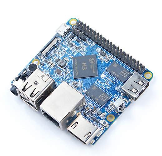
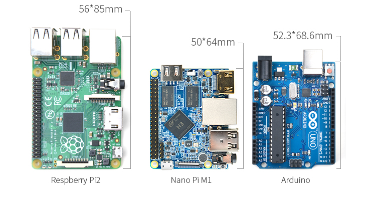
| − | * NanoPi | + | * The NanoPi M1 is an Allwinner H3 based ARM board designed and released by FriendlyARM for hobbyists, makers and electronic fans. It is only two thirds the size of the Raspberry Pi. It is open source. It works with Ubuntu MATE, Debian and etc. |
| − | * NanoPi | + | * The NanoPi M1 uses Allwinner’s H3 Soc. It integrates Ethernet, IR receiver, video/audio output and supports HDMI and AVOUT. It can be powered via the MicroUSB port |
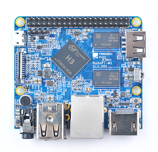
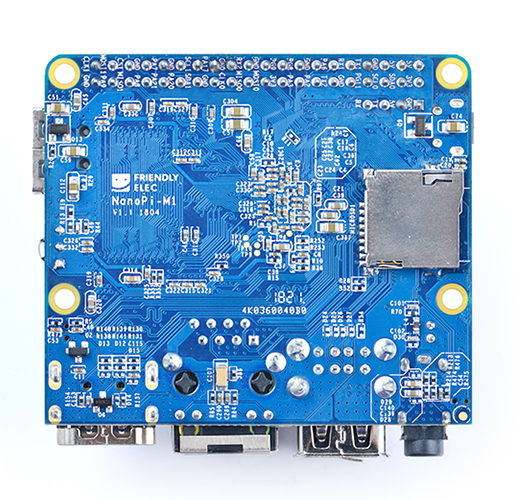
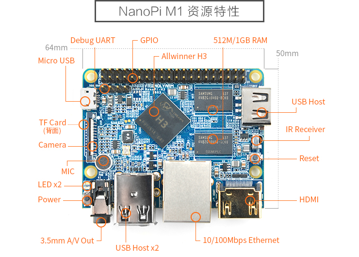
| − | * | + | * In such a small board it still integrates rich interfaces and ports. Besides the popular HDMI, Ethernet, USB-Host, USB-OTG, DVP camera interface and AVOUT (audio and video) it has an onboard Microphone, IR receiver, a serial debug port and a Raspberry Pi compatible 40 pin GPIO pin header. |
==Features== | ==Features== | ||
Revision as of 07:11, 22 March 2016
Contents
1 Introduction
- The NanoPi M1 is an Allwinner H3 based ARM board designed and released by FriendlyARM for hobbyists, makers and electronic fans. It is only two thirds the size of the Raspberry Pi. It is open source. It works with Ubuntu MATE, Debian and etc.
- The NanoPi M1 uses Allwinner’s H3 Soc. It integrates Ethernet, IR receiver, video/audio output and supports HDMI and AVOUT. It can be powered via the MicroUSB port
- In such a small board it still integrates rich interfaces and ports. Besides the popular HDMI, Ethernet, USB-Host, USB-OTG, DVP camera interface and AVOUT (audio and video) it has an onboard Microphone, IR receiver, a serial debug port and a Raspberry Pi compatible 40 pin GPIO pin header.
2 Features
- CPU: Allwinner H3, Quad-core Cortex-A7@1.2GHz
- GPU: Mali400MP2@600MHz,Supports OpenGL ES2.0
- DDR3 RAM: 512MB
- Connectivity: 10/100M Ethernet
- Audio: 3.5mm audio jack/Via HDMI
- Microphone: Onboard microphone
- IR Receiver: Onboard IR receiver
- USB Host:Type A, USB 2.0 x 3
- MicroSD Slot x 1
- MicroUSB: for data transmission and power input, OTG
- Video Output: HDMI 1.4 1080P, CVBS
- DVP Camera Interface: 24pin, 0.5mm pitch FPC seat
- Debug Serial Port: 4Pin, 2.54mm pitch pin header
- GPIO: 2.54mm spacing 40pin, compatible with Raspberry Pi's GPIO. It includes UART, SPI, I2C, IO etc
- User Key: Power LED x 1, Reset x 1
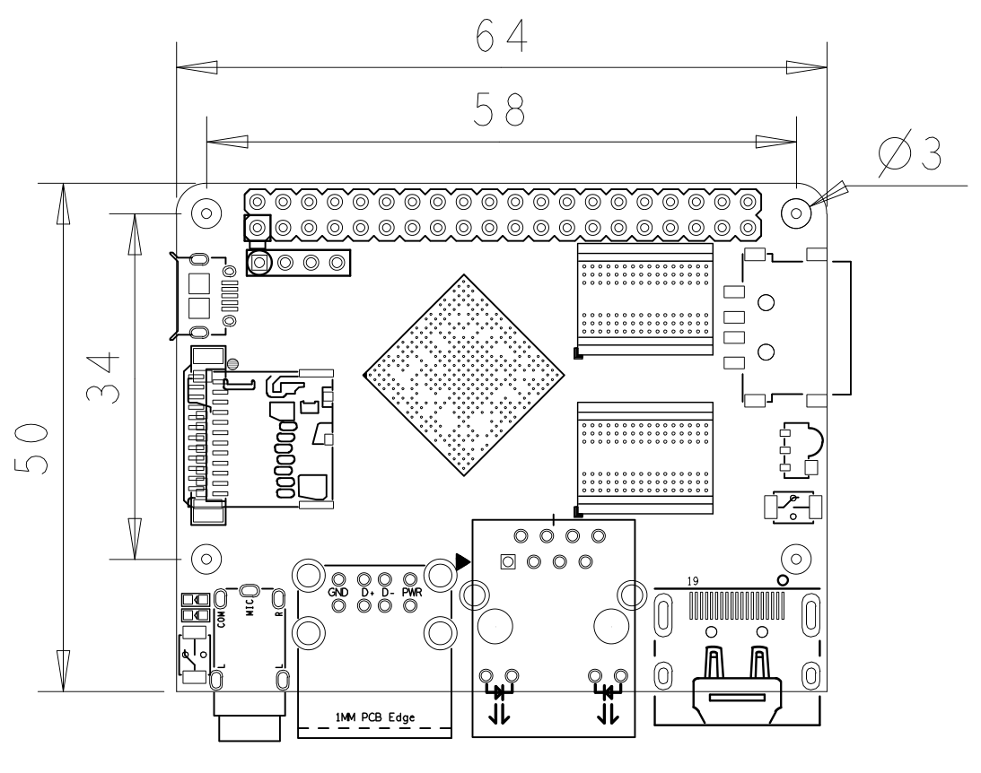
- PC Size: 64 x 50mm
- Power Supply: DC 5V/2A
- OS/Software: u-boot,Ubuntu MATE,Debian
3 Diagram, Layout and Dimension
3.1 Layout
- GPIO Pin Spec
Pin# Name Pin# Name 1 SYS_3.3V 2 VDD_5V 3 I2C0_SDA 4 VDD_5V 5 I2C0_SCL 6 GND 7 GPIOG11 8 UART1_TX/GPIOG6 9 GND 10 UART1_RX/GPIOG7 11 UART2_TX/GPIOA0 12 PWM1/GPIOA6 13 UART2_RTS/GPIOA2 14 GND 15 UART2_CTS/GPIOA3 16 UART1_RTS/GPIOG8 17 SYS_3.3V 18 UART1_CTS/GPIOG9 19 SPI0_MOSI/GPIOC0 20 GND 21 SIP0_MISO/GPIOC1 22 UART2_RX/GPIOA1 23 SPI0_CLK/GPIOC29 24 SPI0_CS/GPIOC3 25 GND 26 SPDIF-OUT/GPIOA17 27 I2C1_SDA/GPIOA19 28 I2C1_SCL/GPIOA18 29 GPIOA20 30 GND 31 GGPIOA21 32 GPIOA7 33 GPIOA8 34 GND 35 UART3_CTS/SPI1_MISO/GPIOA16 36 UART3_TX/SPI1_CS/GPIOA13 37 GPIOA9 38 UART3_RTS/SPI1_MOSI/GPIOA15 39 GND 40 UART3_RX/SPI1_CLK/GPIOA14
- Debug Port(UART0)
Pin# Name 1 GND 2 VDD_5V 3 UART_TXD0 4 UART_RXD0
- DVP Camera IF Pin Spec
Pin# Name Description 1, 2 SYS_3.3V 3.3V power output, to camera modules 7,9,13,15,24 GND Gound, 0V 3 I2C2_SCL I2C Clock Signal 4 I2C2_SDA I2C Data Signal 5 GPIOE15 Regular GPIO, control signals output to camera modules 6 GPIOE14 Regular GPIO, control signals output to camera modules 8 MCLK Clock signals output to camera modules 10 NC Not Connected 11 VSYNC vertical synchronization to CPU from camera modules 12 HREF/HSYNC HREF/HSYNC signal to CPU from camera modules 14 PCLK PCLK signal to CPU from camera modules 16-23 Data bit7-0 data signals
- Note:
- SYS_3.3V: 3.3V power output
- VDD_5V: 5V power input/output. When the external device’s power is greater than the MicroUSB’s the external device is charging the board otherwise the board powers the external device. The input range is 4.7V ~ 5.6V
- All pins are 3.3V and output current is 5mA. It can drive small loads.可以带动小负荷模块,io都不能带负载
- For more details please refer to the document: NanoPi-M1-1603-Schematic.pdf
3.2 Board Dimension
- For more details please refer to: pcb file in dxf
4 快速入门
4.1 准备工作
5 Resources
- Schematic NanoPi-M1-1603-Schematic.pdf
- Dimensional Diagram pcb file in dxf
