Difference between revisions of "Micro2451"
From FriendlyELEC WiKi
(→Breakout Pin Definitions) |
(→Solftware) |
||
| (19 intermediate revisions by 3 users not shown) | |||
| Line 1: | Line 1: | ||
[[Micro2451/zh|查看中文]] | [[Micro2451/zh|查看中文]] | ||
==Introduction== | ==Introduction== | ||
| − | + | [[File:Micro2451-C01.png|thumb|Overview]] | |
| + | [[File:Micro2451-A01.png|thumb|Front]] | ||
| + | [[File:Micro2451-B01.png|thumb|Back]] | ||
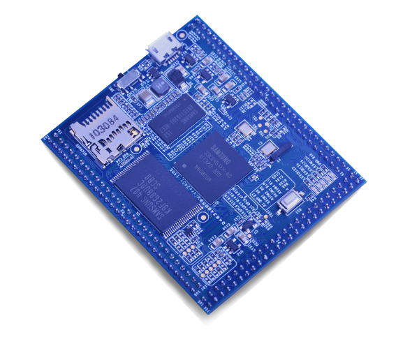
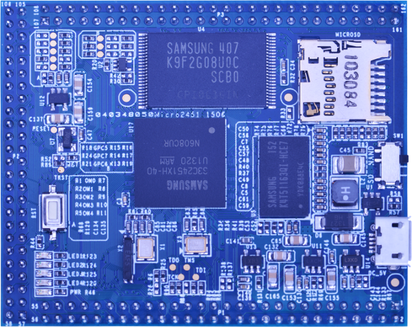
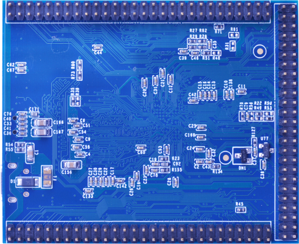
| + | The Micro2451 CPU board is an ARM9 embedded system that uses the Samsung's ARM926EJ S3C2451 System On Chip (SOC). Its clock is 400M Hz and can be up to 533MHz. As an ideal successor of the Mico2440 it has better performance and lower power consumption. | ||
| + | |||
| + | The Micro2451 CPU board's pin specifications are identical to the Micro2440 CPU board's and therefore they work with the same carrier board. | ||
==Features== | ==Features== | ||
* CPU: Samsung S3C2451,Running at 400Mhz | * CPU: Samsung S3C2451,Running at 400Mhz | ||
* RAM: 64M DDR2 | * RAM: 64M DDR2 | ||
| − | * Flash: | + | * Flash: 256MB SLC NandFlash Default , 1GB Optional |
* MicroSD x1:Boot and Storage | * MicroSD x1:Boot and Storage | ||
* MicroUSB x1:Power Supply Only | * MicroUSB x1:Power Supply Only | ||
* LEDs x5:Power LED x1,User LEDs x4 | * LEDs x5:Power LED x1,User LEDs x4 | ||
* Reset Button | * Reset Button | ||
| − | * 2.0mm | + | * 2.0mm Breakout Headers x3,Include: |
** UARTs x3 | ** UARTs x3 | ||
** I2C x1 | ** I2C x1 | ||
| Line 26: | Line 31: | ||
==Interfaces== | ==Interfaces== | ||
| − | ===Breakout | + | ===Breakout Header Definitions=== |
[[File:Micro2451-1506-if.png |thumb|400px|Micro2451-1506 Breakout]] | [[File:Micro2451-1506-if.png |thumb|400px|Micro2451-1506 Breakout]] | ||
* P1 | * P1 | ||
| Line 175: | Line 180: | ||
::#DM_UDEV&DP_UDEV:USB 2.0 Device | ::#DM_UDEV&DP_UDEV:USB 2.0 Device | ||
::#DM_UHOST&DP_UHOST: USB 1.1 Host. 15K pull-down resistors is necessary. | ::#DM_UHOST&DP_UHOST: USB 1.1 Host. 15K pull-down resistors is necessary. | ||
| − | ::# | + | ::#RTC_BATT:3V RTC backup battery input. |
::#AIN0-AIN2,AIN6-AIN9:Input channels of S3C2451 SOC 12-Bit ADC. Channel 0-2,and channel 6-9, voltage input rang: 0-3.3V | ::#AIN0-AIN2,AIN6-AIN9:Input channels of S3C2451 SOC 12-Bit ADC. Channel 0-2,and channel 6-9, voltage input rang: 0-3.3V | ||
| Line 185: | Line 190: | ||
==Dimensions== | ==Dimensions== | ||
[[File:Micro2451-1506-Dimensions.png |frameless|400px| Micro2451-1506 机械尺寸]] | [[File:Micro2451-1506-Dimensions.png |frameless|400px| Micro2451-1506 机械尺寸]] | ||
| − | :More detail [ | + | :More detail: [http://wiki.friendlyarm.com/wiki/images/9/9a/Micro2451-1506-Dimensions%28dxf%29.zip Micro2451-1506-Dimensions(dxf).zip] |
==Resources== | ==Resources== | ||
| − | * Schematic | + | * Schematic ( [http://wiki.friendlyarm.com/wiki/images/f/fc/Micro2451-1506-Schematic.pdf Micro2451-1506-Schematic.pdf] ) |
| − | * Dimensions | + | * Dimensions ( [http://wiki.friendlyarm.com/wiki/images/9/9a/Micro2451-1506-Dimensions%28dxf%29.zip Micro2451-1506-Dimensions(dxf).zip] ) |
| + | * S3C2451 Datasheet ( [http://www.mediafire.com/view/i79d7v49hp0jca2/S3C2451_UM_REV1%5B1%5D.pdf S3C2451_UM_REV1.10.pdf] ) | ||
| + | |||
| + | ==Solftware== | ||
| + | *[http://112.124.9.243/dvd/FriendlyARM-2451-DVD/ FriendlyARM-2451-DVD] | ||
| + | *[https://www.mediafire.com/folder/b1lnc9lyn468q//2451Board MediaFire] | ||
Latest revision as of 11:07, 5 March 2016
Contents
[hide]1 Introduction
The Micro2451 CPU board is an ARM9 embedded system that uses the Samsung's ARM926EJ S3C2451 System On Chip (SOC). Its clock is 400M Hz and can be up to 533MHz. As an ideal successor of the Mico2440 it has better performance and lower power consumption.
The Micro2451 CPU board's pin specifications are identical to the Micro2440 CPU board's and therefore they work with the same carrier board.
2 Features
- CPU: Samsung S3C2451,Running at 400Mhz
- RAM: 64M DDR2
- Flash: 256MB SLC NandFlash Default , 1GB Optional
- MicroSD x1:Boot and Storage
- MicroUSB x1:Power Supply Only
- LEDs x5:Power LED x1,User LEDs x4
- Reset Button
- 2.0mm Breakout Headers x3,Include:
- UARTs x3
- I2C x1
- PWMs x4
- USB 1.1 HOST x1
- USB 2.0 Device x1
- MMC/SDIO x1
- IIS x1
- ADCs x7
- SROM Bus 25-bit Address, 16-bit Data and 5 Chip Select
- RGB LCD 24-bit Interface x1
- DVP Camera Interface x1
- Configurable GPIOs or External Interrupts x22
3 Interfaces
3.1 Breakout Header Definitions
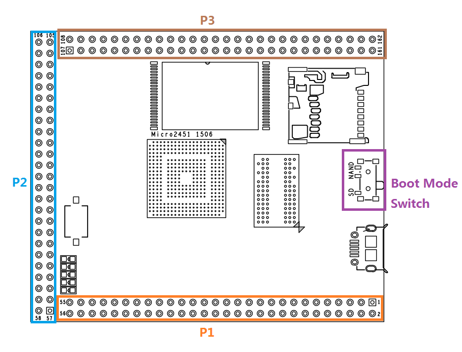
- P1
P1 Pin# PCB Pin# Name P1 Pin# PCB Pin# Name 1 1 VDD_5V 2 2 DGND 3 3 EINT19/GPG11 4 4 EINT18/GPG10 5 5 EINT17/GPG9 6 6 EINT16/GPG8 7 7 EINT15/GPG7 8 8 EINT14/GPG6 9 9 EINT13/GPG5 10 10 EINT11/GPG3 11 11 EINT12/GPG4 12 12 EINT6/GPF6 13 13 EINT5/GPF5 14 14 EINT4/GPF4 15 15 EINT3/GPF3 16 16 EINT2/GPF2 17 17 EINT1/GPF1 18 18 EINT0/GPF0 19 19 GPL5 20 20 MMC0CLK 21 21 MMC0CMD 22 22 MMC0DATA2 23 23 MMC0DATA3 24 24 MMC0DATA0 25 25 MMC0DATA1 26 26 BOOT_CS 27 27 NC 28 28 M_nRESET 29 29 DM_UDEV 30 30 DP_UDEV 31 31 DM_UHOST 32 32 DP_UHOST 33 33 AIN2 34 34 RTC_BATT 35 35 AIN0 36 36 AIN1 37 37 TOUT2/GPB2 38 38 TOUT3/GPB3 39 39 TCLK/GPB4 40 40 IIS0LRCK 41 41 IIS0SCLK 42 42 IIS0CDCLK 43 43 IIS0SDI 44 44 IIS0SDO 45 45 TOUT0/GPB0 46 46 EINT10/GPG2 47 47 UART2_TX 48 48 UART2_RX 49 49 UART1_TX 50 50 UART1_RX 51 51 UART0_TX 52 52 UART0_RX 53 53 UART0_CTS 54 54 USRT0_RTS 55 55 I2C0SDA 56 56 I2C0SCL
- P2
P2 Pin# PCB Pin# Name P2 Pin# PCB Pin# Name 1 57 AIN6/YM 2 58 AIN7/YP 3 59 AIN8/XM 4 60 AIN9/XP 5 61 LCD R-bit6 6 62 LCD R-bit7 7 63 LCD R-bit4 8 64 LCD R-bit5 9 65 LCD R-bit2 10 66 LCD R-bit3 11 67 LCD R-bit0 12 68 LCD R-bit1 13 69 LCD G-bit6 14 70 LCD G-bit7 15 71 LCD G-bit4 16 72 LCD G-bit5 17 73 LCD G-bit2 18 74 LCD G-bit3 19 75 LCD G-bit0 20 76 LCD G-bit1 21 77 LCD B-bit6 22 78 LCD B-bit7 23 79 LCD B-bit4 24 80 LCD B-bit5 25 81 LCD B-bit2 26 82 LCD B-bit3 27 83 LCD B-bit0 28 84 LCD B-bit1 29 85 TOUT1/GPB1 30 86 LCD DEN 31 87 LCD VSYNC 32 88 LCD HSYNC 33 89 LCD CLK 34 90 GPC0 35 91 Camera DATA7 36 92 Camera DATA6 37 93 Camera DATA5 38 94 Camera DATA4 39 95 Camera DATA3 40 96 Camera DATA2 41 97 Camera DATA1 42 98 Camera DATA0 43 99 Camera XCLK 44 100 Camera PCLK 45 101 Camera VSYNC 46 102 Camera HREF 47 103 EINT20/GPG12 48 104 GPJ12 49 105 VDD_5V 50 106 DGND
- P3
P3 Pin# PCB Pin# Name P3 Pin# PCB Pin# Name 1 107 EINT7/GPF7 2 108 EINT9/GPG1 3 109 nRCS1/GPA12 4 110 nRCS3/GPA14 5 111 nRCS2/GPA13 6 112 nRCS5/GPA16 7 113 nRCS4/GPA15 8 114 nRWE 9 115 nROE 10 116 nRSTOUT 11 117 nWAIT 12 118 nXDACK0/GPB9 13 119 SROM ADDR0 14 120 nDREQ0/GPB10 15-38 121-144 SROM ADDR1-24 39-54 145-160 SROM DATA0-15 55 161 VDD_5V 56 162 DGND
- Some Pin Descriptions:
- VDD_5V: 4.7-5.6V power supply input. 5V/500mA is recommended.
- BOOT_CS: Boot mode select signal input. When BOOT_CS is floating or high level, Micro2451 will boot from MicroSD card, otherwise boot from NandFlash. BOOT_CS is also connected to the boot mode switch. So, if you used BOOT_CS in your project, the boot mode switch should on SD side (BOOT_CS flaoting).
- M_nRESET:Manual reset input, active low.
- DM_UDEV&DP_UDEV:USB 2.0 Device
- DM_UHOST&DP_UHOST: USB 1.1 Host. 15K pull-down resistors is necessary.
- RTC_BATT:3V RTC backup battery input.
- AIN0-AIN2,AIN6-AIN9:Input channels of S3C2451 SOC 12-Bit ADC. Channel 0-2,and channel 6-9, voltage input rang: 0-3.3V
3.2 Boot Mode Switch, MicroSD and MicroUSB
- Boot Mode Switch:On SD side, boot from MicroSD card. On NAND side, boot from NandFlash
- MicroSD:Boot and Storage.
- MicroUSB:Power supply only
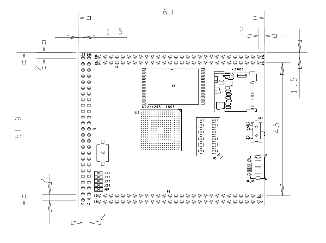
4 Dimensions
- More detail: Micro2451-1506-Dimensions(dxf).zip
5 Resources
- Schematic ( Micro2451-1506-Schematic.pdf )
- Dimensions ( Micro2451-1506-Dimensions(dxf).zip )
- S3C2451 Datasheet ( S3C2451_UM_REV1.10.pdf )
