Difference between revisions of "Matrix - Ball Rolling Switch"
| Line 1: | Line 1: | ||
[[Matrix - BAll Rolling Switch/zh|查看中文]] | [[Matrix - BAll Rolling Switch/zh|查看中文]] | ||
| − | == | + | ==Introduction== |
[[File:BAll Rolling Switch01.png|thumb|BAll Rolling Switch]] | [[File:BAll Rolling Switch01.png|thumb|BAll Rolling Switch]] | ||
| − | *Matrix- | + | *The Matrix-Ball_Rolling_Switch module is a ball switch. Its electrical characteristics are very similar to a mercury switch's however a mercury switch is easily broken, oxidized, leaking and not environment-friendly. This ball switch prevents all these issues. |
| − | * | + | *The switch is free to move any angle and if that angle is between 15 degrees and 45 degrees a signal will be generated and used as an input to a Schmitt trigger. |
| − | == | + | |
| + | ==Features== | ||
* GPIO | * GPIO | ||
| − | * | + | * Small |
| − | * 2. | + | * 2.54 mm spacing pin header |
| − | * | + | * PCB Dimension(mm):16 x 16 |
[[File:BAll Rolling Switchpcb.png | frameless|400px|BAll Rolling Switch-01.PCB]] | [[File:BAll Rolling Switchpcb.png | frameless|400px|BAll Rolling Switch-01.PCB]] | ||
| − | * | + | * Pin Description: |
{| class="wikitable" | {| class="wikitable" | ||
|- | |- | ||
| − | | | + | |Pin || Description |
|- | |- | ||
| − | |S || | + | |S || Digital GPIO |
|- | |- | ||
| − | |V || | + | |V || Supply Voltage 5V |
|- | |- | ||
| − | |G || | + | |G || Ground |
|} | |} | ||
| − | == | + | ==Basic Device Operation== |
3-Pin 2.54mm排针,V接电源,G接地,S为模块数字信号输出,当开关倾斜,开关内的金属球珠滚动到开关一侧,导通触点时,开关输出高电平到施密特触发器,再通过触发器内部的逆变器反向,模块输出低电平;当开关内的金属球珠滚动到开关的另一侧,断开触点时,滚珠开关输出低电平到施密特触发器,触发器内部的逆变器反向,此时,模块输出高电平。 | 3-Pin 2.54mm排针,V接电源,G接地,S为模块数字信号输出,当开关倾斜,开关内的金属球珠滚动到开关一侧,导通触点时,开关输出高电平到施密特触发器,再通过触发器内部的逆变器反向,模块输出低电平;当开关内的金属球珠滚动到开关的另一侧,断开触点时,滚珠开关输出低电平到施密特触发器,触发器内部的逆变器反向,此时,模块输出高电平。 | ||
Revision as of 09:36, 25 December 2015
Contents
1 Introduction
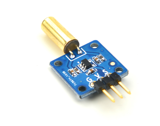
- The Matrix-Ball_Rolling_Switch module is a ball switch. Its electrical characteristics are very similar to a mercury switch's however a mercury switch is easily broken, oxidized, leaking and not environment-friendly. This ball switch prevents all these issues.
- The switch is free to move any angle and if that angle is between 15 degrees and 45 degrees a signal will be generated and used as an input to a Schmitt trigger.
2 Features
- GPIO
- Small
- 2.54 mm spacing pin header
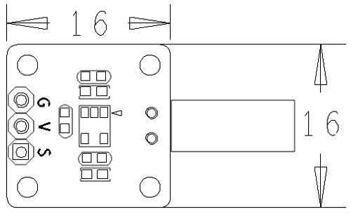
- PCB Dimension(mm):16 x 16
- Pin Description:
| Pin | Description |
| S | Digital GPIO |
| V | Supply Voltage 5V |
| G | Ground |
3 Basic Device Operation
3-Pin 2.54mm排针,V接电源,G接地,S为模块数字信号输出,当开关倾斜,开关内的金属球珠滚动到开关一侧,导通触点时,开关输出高电平到施密特触发器,再通过触发器内部的逆变器反向,模块输出低电平;当开关内的金属球珠滚动到开关的另一侧,断开触点时,滚珠开关输出低电平到施密特触发器,触发器内部的逆变器反向,此时,模块输出高电平。
4 下载Matrix源码
Matrix配件相关的代码是完全开源的,统一由一个仓库进行管理:git://github.com/friendlyarm/matrix.git
该仓库里不同的分支代表着Matrix配件所支持的不同开发板。
- nanopi分支用于支持NanoPi;
- nanopi2分支用于支持NanoPi 2;
- tiny4412分支用于支持Tiny4412;
- raspberrypi分支用于支持RaspberryPi;
在主机PC上安装git,以Ubuntu14.04为例
$ sudo apt-get install git
克隆Matrix配件代码仓库
$ git clone git://github.com/friendlyarm/matrix.git
克隆完成后会得到一个名为matrix的目录,里面存放着所有Matrix配件的代码。
5 与NanoPi 2连接使用
5.1 硬件连接
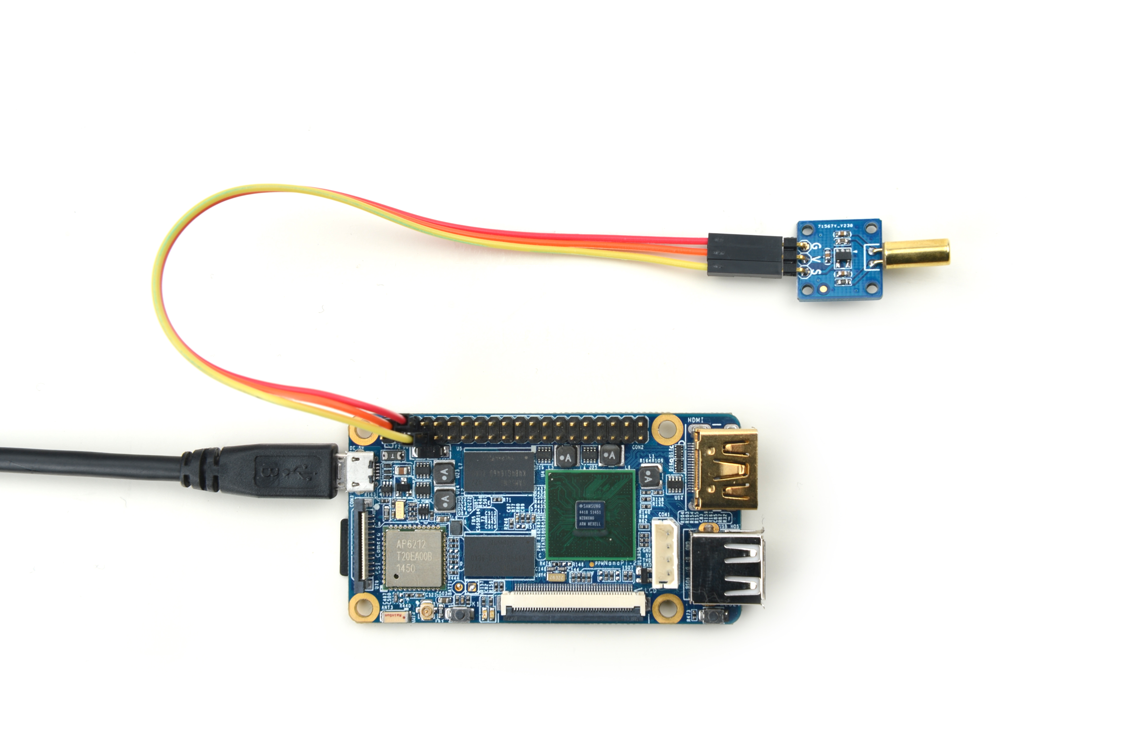
参考下图连接模块Matrix-Ball_Rolling_Switch和NanoPi2:

连接说明:
| Matrix-Ball_Rolling_Switch | NanoPi2 |
| S | Pin7 |
| V | Pin4 |
| G | Pin6 |
5.2 编译测试程序
进入Matrix代码仓库,切换到nanopi2分支
$ cd matrix
$ git checkout nanopi2
编译Matrix配件代码
$ make CROSS_COMPILE=arm-linux- clean
$ make CROSS_COMPILE=arm-linux-
$ make CROSS_COMPILE=arm-linux- install
注意:请确保你的主机PC当前使用的交叉编译器为NanoPi 2配套的arm-linux-gcc-4.9.3。
编译成功后库文件位于install/lib目录下,而测试程序则位于install/usr/bin目录下,模块Matrix-Ball_Rolling_Switch对应的测试程序为matrix-ball_switch。
5.3 运行测试程序
将带有Debian系统的SD卡插入一台运行Linux的电脑,可以挂载SD卡上的boot和rootfs分区。
假设rootfs分区的挂载路径为/media/rootfs,执行以下命令将Matrix的硬件驱动、库文件和测试程序拷贝到NanoPi 2的文件系统上。
$ cp modules /media/rootfs/ -r
$ cp install/lib/* /media/rootfs/lib/ -d
$ cp install/usr/bin/* /media/rootfs/usr/bin/
将SD卡重新插入NanoPi 2,上电启动,在Debian的shell终端中执行以下命令运行模块Matrix-Ball_Rolling_Switch的测试程序。
$ matrix-ball_switch运行效果如下:

将模块竖立起来,利用开关中的小珠的滚动,制造与金属端子的触碰或改变光线行进的路线,就能产生导通的效果。
5.4 代码展示
static struct sensor brSwitch[] = {
        {
                GPIO_PIN(7),
                IRQ_TYPE_EDGE_FALLING,
        }
};

int main(int argc, char ** argv)
{
    int i;
    int retSize = -1;
    char value[ARRAY_SIZE(brSwitch)];
    int devFD = -1;

    if (argc == 2) {
        brSwitch[0].pin = atoi(argv[1]);
    }

    printf("Using GPIO_PIN(%d)\n", brSwitch[0].pin);
    if ((devFD =sensorInit(brSwitch, ARRAY_SIZE(brSwitch))) == -1) {
        printf("Fail to init sensor\n");
        return -1;
    }
    printf("Lean the switch...\n");
    if ((retSize = sensorRead(devFD, value, ARRAY_SIZE(brSwitch))) == -1) {
        printf("Fail to read sensors\n");
    }
    if (retSize > 0) {
        i = 0;
        for (i=0; i<retSize; i++) {
            printf("Switch[%d]:%d\n", i, value[i]);
        }
    }
    sensorDeinit(devFD);
    return 0;
}

