Difference between revisions of "FriendlyThings for Rockchip"
(updated by API) |
(updated by API) |
||
| Line 145: | Line 145: | ||
[[File:rk3399-android-gpio.png|frameless|GPIO]] | [[File:rk3399-android-gpio.png|frameless|GPIO]] | ||
===ADC=== | ===ADC=== | ||
| − | + | You can access ADC like accessing files on Android. | |
| + | ====RK3588==== | ||
| + | The file node corresponding to channel2 is shown below: | ||
| + | ::{| class="wikitable" | ||
| + | |- | ||
| + | | style="background: PaleTurquoise; color: black" | '''频道''' | ||
| + | | style="background: PaleTurquoise; color: black" |'''文件节点''' | ||
| + | |- | ||
| + | |Channel 2||/sys/devices/platform/fec10000.saradc/iio:device0/in_voltage2_raw | ||
| + | |} | ||
| + | ====RK3568==== | ||
| + | The file node corresponding to channel2 is shown below: | ||
| + | ::{| class="wikitable" | ||
| + | |- | ||
| + | | style="background: PaleTurquoise; color: black" | '''频道''' | ||
| + | | style="background: PaleTurquoise; color: black" |'''文件节点''' | ||
| + | |- | ||
| + | |Channel 2||/sys/devices/platform/fe720000.saradc/iio:device0/in_voltage2_raw | ||
| + | |} | ||
| + | ====RK3399==== | ||
RK3399 populates three ADC channels 0, 2 and 3 and here is a list of the channels and their corresponding nodes: | RK3399 populates three ADC channels 0, 2 and 3 and here is a list of the channels and their corresponding nodes: | ||
::{| class="wikitable" | ::{| class="wikitable" | ||
| Line 158: | Line 177: | ||
|Channel 3||/sys/devices/platform/ff100000.saradc/iio:device0/in_voltage3_raw | |Channel 3||/sys/devices/platform/ff100000.saradc/iio:device0/in_voltage3_raw | ||
|} | |} | ||
| − | |||
| − | |||
| − | |||
===PWM=== | ===PWM=== | ||
| + | ====RK3399==== | ||
<b>Note: The PWM interface is already used by the fan by default. If you want to control the PWM by yourself, you need to disable the fan first, <br /> | <b>Note: The PWM interface is already used by the fan by default. If you want to control the PWM by yourself, you need to disable the fan first, <br /> | ||
Please refer to: </b>[[Template:RK3399 Android PWMFan]]<br /> | Please refer to: </b>[[Template:RK3399 Android PWMFan]]<br /> | ||
<br /> | <br /> | ||
You can access PWMs by calling sysfs APIs. You can access the nodes under the "/sys/class/pwm/pwmchip1" directory. Here is code sample to control a PWM fan: | You can access PWMs by calling sysfs APIs. You can access the nodes under the "/sys/class/pwm/pwmchip1" directory. Here is code sample to control a PWM fan: | ||
| − | ====APIs for Accessing PWM==== | + | =====APIs for Accessing PWM===== |
* Export PWM0 to users | * Export PWM0 to users | ||
<syntaxhighlight lang="bash"> | <syntaxhighlight lang="bash"> | ||
| Line 178: | Line 195: | ||
echo 45000 > /sys/class/pwm/pwmchip1/pwm0/duty_cycle | echo 45000 > /sys/class/pwm/pwmchip1/pwm0/duty_cycle | ||
</syntaxhighlight> | </syntaxhighlight> | ||
| − | ====Testing PWM==== | + | =====Testing PWM===== |
Connect a PWM fan(3 pins) to a NanoPC-T4's fan port to test it. | Connect a PWM fan(3 pins) to a NanoPC-T4's fan port to test it. | ||
[[File:rk3399-android-pwm.png|frameless|PWM]] | [[File:rk3399-android-pwm.png|frameless|PWM]] | ||
===I2C=== | ===I2C=== | ||
| − | + | ====RK3399==== | |
To test I2C we connected a FriendlyElec's LCD1602 module to a NanoPC-T4 and ran the I2C demo program: | To test I2C we connected a FriendlyElec's LCD1602 module to a NanoPC-T4 and ran the I2C demo program: | ||
::{| class="wikitable" | ::{| class="wikitable" | ||
| Line 203: | Line 220: | ||
===RTC=== | ===RTC=== | ||
| + | '''Note: Scheduled power on/off is only supported on certain models, such as NanoPC-T4.'''<br /> | ||
You can access RTC by calling APIs under the "/sys/class/rtc/rtc0/" directory. For instance you can check the current RTC time by running the following commands:<br /> | You can access RTC by calling APIs under the "/sys/class/rtc/rtc0/" directory. For instance you can check the current RTC time by running the following commands:<br /> | ||
<syntaxhighlight lang="bash"> | <syntaxhighlight lang="bash"> | ||
Revision as of 06:15, 4 August 2023
查看中文
Note: the steps and methods presented here apply to all FriendlyElec's Rockchip based boards. For steps and methods that apply to other platforms refer to FriendlyThings
Contents
1 Introduction
FriendlyThings is an Android SDK developed by FriendlyElec to access hardware. Users can use it to access various hardware resources Uart, SPI, I2C, GPIO etc on a FriendlyElec ARM board under Android. This SDK is based on Android-NDK. Users can use it to develop popular IoT applications without directly interacting with drivers.
2 Android Versions
The Android BSPs provided by FriendlyElec already have FriendlyThings SDK(libfriendlyarm-things.so) and currently have two version:
- Android 7.1.2-rk3399
BSP source code download link: https://gitlab.com/friendlyelec/rk3399-nougat
BSP source code location on the network disk: sources/rk3399-android-7.git-YYYYMMDD.tgz
Latest ROM download link: http://download.friendlyelec.com/NanoPC-T4
- Android 8.1-rk3399
BSP source code download link: https://gitlab.com/friendlyelec/rk3399-android-8.1
BSP source code location on the network disk: sources/rk3399-android-8.1.git-YYYYMMDD.tgz
Latest ROM download link: http://download.friendlyelec.com/NanoPC-T4
3 List of Applicable Boards
FriendlyThings SDK(libfriendlyarm-things.so) works with the following FriendlyElec RK3399/RK3568/RK3588 based boards:
- NanoPC-T6
- NanoPi-R6S/R6C
- NanoPi-R5S/R5C
- NanoPC-T4
- NanoPi M4 (an external eMMC module is needed)
- NanoPi NEO4 (an external eMMC module is needed)
FriendlyThings might also work with other FriendlyElec boards such as Samsung S5P4418/S5P6818, Samsung S5PV210, Allwinner H3/H5 etc. For more details refer to FriendlyThings
4 Quick Start
4.1 Step 1: Include libfriendlyarm-things.so in APP
Clone the following library locally:
git clone https://github.com/friendlyarm/friendlythings-sdk
Copy all the files under the libs directory to your working directory and create a "com/friendlyarm" directory in your Android project's src directory, copy the whole "java/FriendlyThings" to your newly created "com/friendlyarm" directory. The whole project directory will look like this(Note:AndroidStudio's project may be a little bit different):
YourProject/
├── AndroidManifest.xml
├── libs
│   ├── arm64-v8a
│   │   └── libfriendlyarm-things.so
│   └── armeabi
│       └── libfriendlyarm-things.so
├── src
│   └── com
│       └── friendlyarm
│           ├── FriendlyThings
│           │   ├── BoardType.java
│           │   ├── FileCtlEnum.java
│           │   ├── GPIOEnum.java
│           │   ├── HardwareControler.java
│           │   ├── SPIEnum.java
│           │   ├── SPI.java
│           │   └── WatchDogEnum.java
Import the following components and the major APIs are included in the HardwareControler.java file:
import com.friendlyarm.FriendlyThings.HardwareControler;
import com.friendlyarm.FriendlyThings.SPIEnum;
import com.friendlyarm.FriendlyThings.GPIOEnum;
import com.friendlyarm.FriendlyThings.FileCtlEnum;
import com.friendlyarm.FriendlyThings.BoardType;
4.2 Step 2: Give APP System Right
Your app needs the system right to access hardware resources;
Give your app the system right by making changes in the AndroidManifest.xml file and the Android.mk file;
It is better to include your app in your Android source code and compile them together. If your app is not compiled together with your Android source code you have to go through tedious steps to compile your app and sign your app to give it the system right.
4.2.1 Modify AndroidManifest.xml
Add the following line in the manifest node in the AndroidManifest.xml file:
android:sharedUserId="android.uid.system"
4.2.2 Modify Android.mk
Create an Android.mk file(the simplest way is to copy a sample Android.mk file), modify the Android.mk file by adding a line LOCAL_CERTIFICATE := platform :
LOCAL_PATH:= $(call my-dir)
include $(CLEAR_VARS)

LOCAL_SRC_FILES := $(call all-subdir-java-files)

LOCAL_PACKAGE_NAME := Project Name

LOCAL_CERTIFICATE := platform
LOCAL_MODULE_TAGS := optional
LOCAL_CFLAGS := -lfriendlyarm-hardware

include $(BUILD_PACKAGE)
4.3 Final Step: Compile Your APP Together with Android Source Code
Go to Android source code's root directory and run "setenv.sh" to export environmental variables, enter your app's directory and run "mm" to compile:
For example: compile the GPIO_LED_Demo on RK3399:
cd rk3399-android-8.1
. setenv.sh
cd vendor/friendlyelec/apps/GPIO_LED_Demo
mm
4.4 Sample project in Android Studio
https://github.com/friendlyarm/AndroidStudio-GPIODemo
5 APIs in libfriendlyarm-things.so Library
Refer to this wiki site:FriendlyThings APIs
6 Access Hardware on Android
6.1 Serial Port
The kernel has enabled the following serial ports for testing by default (should be based on kernel dts configuration), to use more serial ports you can configure the kernel dts yourself:
| CPU | Model | Port | Device Node |
|---|---|---|---|
| RK3588 | NanoPC-T6 | UART6 | /dev/ttyS6 |
| RK3588S | NanoPi-R6S/R6C | UART5 | /dev/ttyS5 |
| RK3568 | NanoPi-R5S | UART9 | /dev/ttyS9 |
| RK3399 | NanoPC-T4 | UART4 | /dev/ttyS4 |
6.1.1 APIs for Accessing Serial Ports
HardwareControler.openSerialPortEx //opens a serial port.
HardwareControler.select   //polls a serial port's status and checks if it has data to be read or if data can be written to it.
HardwareControler.read     //reads data from a serial port.
HardwareControler.write    //writes data to a serial port.
HardwareControler.close    //closes a serial port.
For more details refer to :FriendlyThings APIs
6.2 GPIO
You can access GPIO by calling sysfs APIs. You need to access the "/sys/class/gpio" directory, write a GPIO index number you want to access to the export file, and set the GPIO's direction and value.
The following lists the pins that the kernel configures as GPIO (should be based on kernel dts configuration):
Here is a list of GPIOs FriendlyElec's RK3399 boards support:
6.2.1 NanoPC T6
Physical Index GPIO Index Pin7 106 Pin12 111 Pin15 39 Pin16 107 Pin18 108 Pin26 40
6.2.2 NanoPi R6C
6.2.3 NanoPC T4
Physical Index GPIO Index Pin11 33 Pin12 50 Pin15 36 Pin16 54 Pin18 55 Pin22 56 Pin37 96 Pin38 125 Pin40 126
6.2.4 NanoPi M4/M4v2/M4B/NEO4
Physical Index Linux Index Pin11 33 Pin12 50 Pin15 36 Pin16 54 Pin18 55 Pin22 56
6.2.5 SOM-RK3399/SOM-RK3399v2
Physical Index GPIO Index Pin7 41 Pin9 42
6.2.6 APIs for Accessing GPIO
HardwareControler.exportGPIOPin      //exports a GPIO.
HardwareControler.setGPIODirection   //sets a GPIO's direction.
HardwareControler.getGPIODirection   //gets a GPIO's direction.
HardwareControler.setGPIOValue    //sets a GPIO's value.
HardwareControler.getGPIOValue    //gets a GPIO's value
HardwareControler.unexportGPIOPin //unexports a GPIO.
For more details refer to:FriendlyThings APIs
6.2.7 Testing GPIO
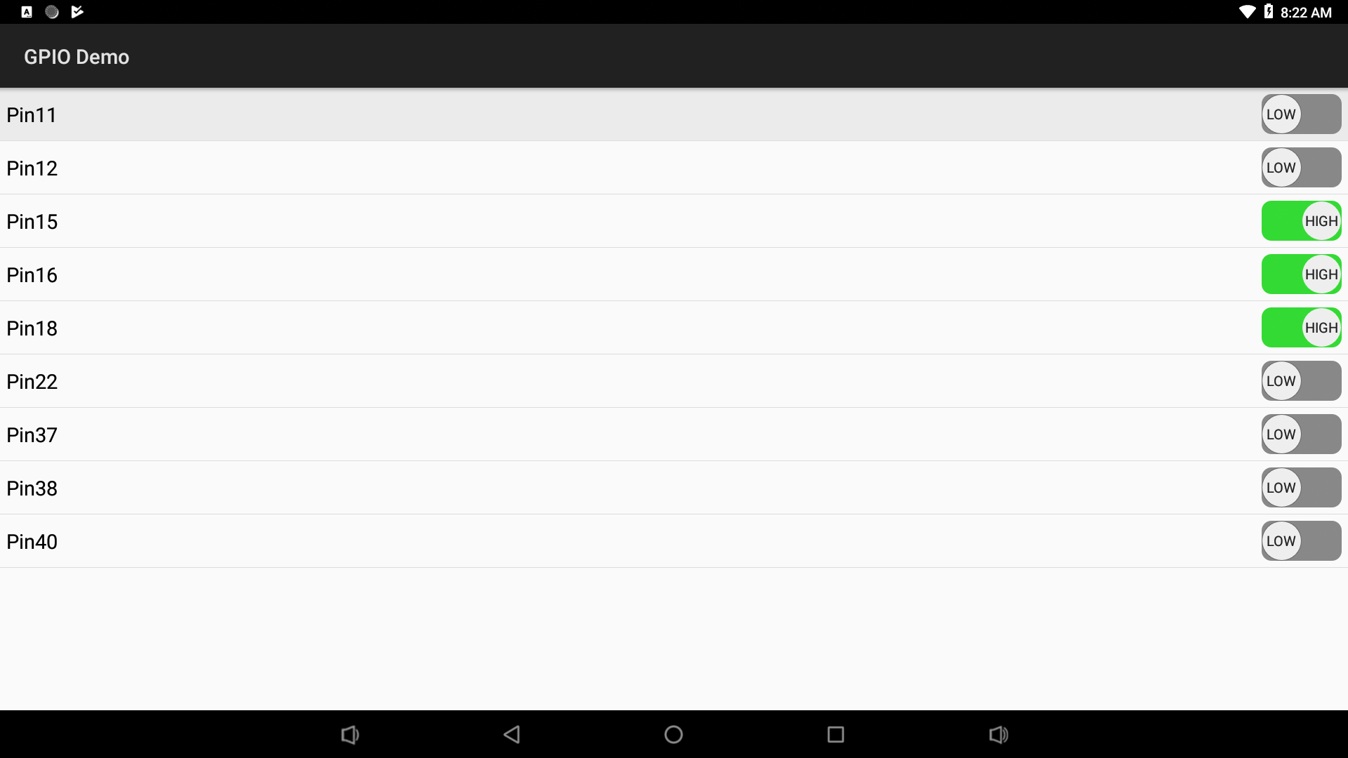
You can use a FriendlyElec's LED module to test GPIOs. Set a HIGH to turn on the LED and a LOW to turn off the LED.
6.3 ADC
You can access ADC like accessing files on Android.
6.3.1 RK3588
The file node corresponding to channel2 is shown below:
频道 文件节点 Channel 2 /sys/devices/platform/fec10000.saradc/iio:device0/in_voltage2_raw
6.3.2 RK3568
The file node corresponding to channel2 is shown below:
频道 文件节点 Channel 2 /sys/devices/platform/fe720000.saradc/iio:device0/in_voltage2_raw
6.3.3 RK3399
RK3399 populates three ADC channels 0, 2 and 3 and here is a list of the channels and their corresponding nodes:
Channel Node Channel 0 /sys/devices/platform/ff100000.saradc/iio:device0/in_voltage0_raw Channel 2 /sys/devices/platform/ff100000.saradc/iio:device0/in_voltage2_raw Channel 3 /sys/devices/platform/ff100000.saradc/iio:device0/in_voltage3_raw
6.4 PWM
6.4.1 RK3399
Note: The PWM interface is already used by the fan by default. If you want to control the PWM by yourself, you need to disable the fan first,
Please refer to: Template:RK3399 Android PWMFan
You can access PWMs by calling sysfs APIs. You can access the nodes under the "/sys/class/pwm/pwmchip1" directory. Here is code sample to control a PWM fan:
6.4.1.1 APIs for Accessing PWM
- Export PWM0 to users
echo 0 > /sys/class/pwm/pwmchip1/export
- Control a PWM fan's speed by setting the PWM's period and duty_cycle.
echo 0 > /sys/class/pwm/pwmchip1/pwm0/enable
echo 50000 > /sys/class/pwm/pwmchip1/pwm0/period
echo 1 > /sys/class/pwm/pwmchip1/pwm0/enable
echo 45000 > /sys/class/pwm/pwmchip1/pwm0/duty_cycle
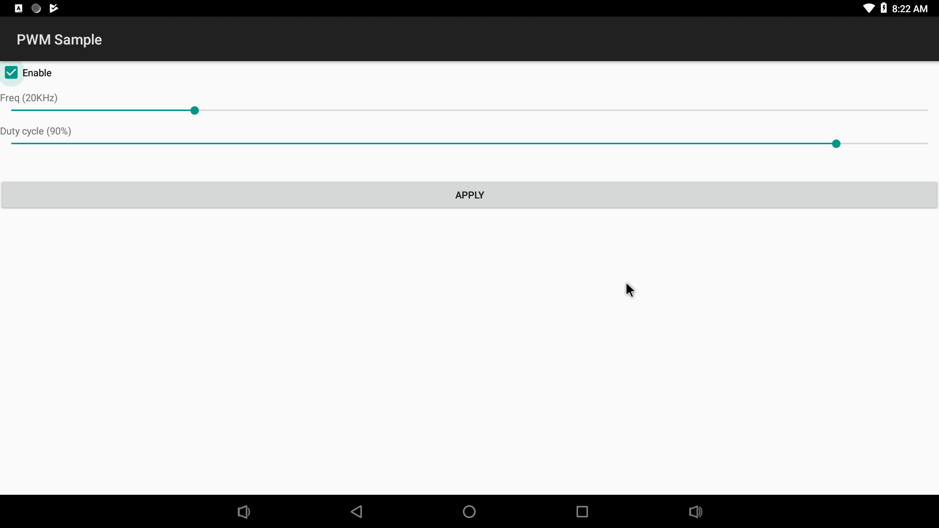
6.4.1.2 Testing PWM
Connect a PWM fan(3 pins) to a NanoPC-T4's fan port to test it.
6.5 I2C
6.5.1 RK3399
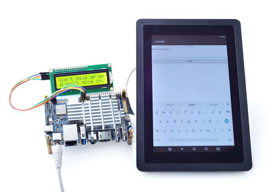
To test I2C we connected a FriendlyElec's LCD1602 module to a NanoPC-T4 and ran the I2C demo program:
Physical Index I2C Functions Pin3 I2C2_SDA(3V) Pin4 VCC5V0_SYS Pin5 I2C2_SCL(3V) Pin6 GND
6.6 RTC
Note: Scheduled power on/off is only supported on certain models, such as NanoPC-T4.
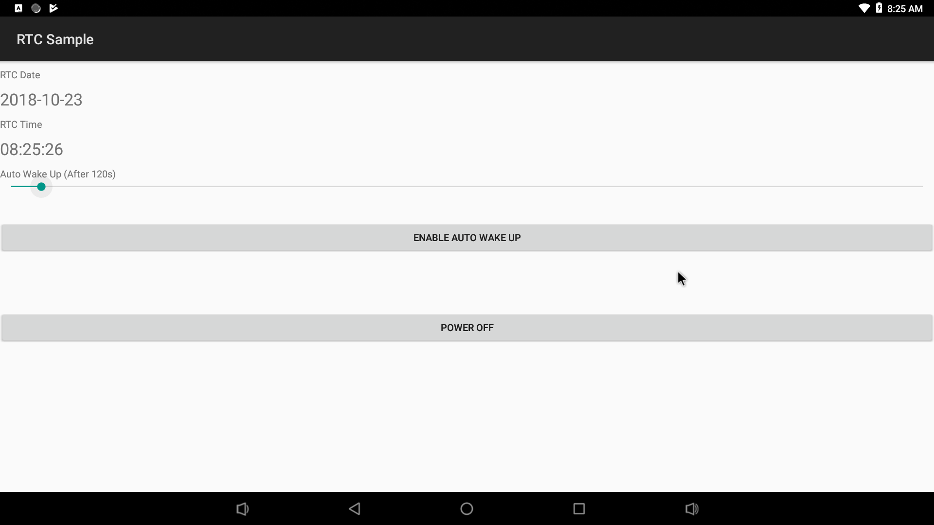
You can access RTC by calling APIs under the "/sys/class/rtc/rtc0/" directory. For instance you can check the current RTC time by running the following commands:
cat /sys/class/rtc/rtc0/date
# 2018-10-20
cat /sys/class/rtc/rtc0/time
# 08:20:14
Set power-on time. For instance power on in 120 seconds:
#Power on in 120 seconds
echo +120 >  /sys/class/rtc/rtc0/wakealarm
6.7 Watch dog
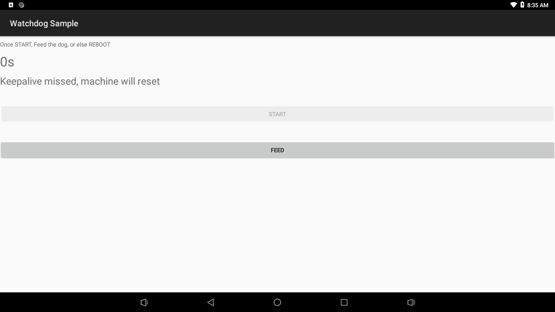
It is quite straightforward to access the watch dog. You can simply open the "/dev/watchdog" device and write characters to it.If for any reason no characters can be written to the device the system will reboot in a moment:
mWatchDogFD = HardwareControler.open("/dev/watchdog", FileCtlEnum.O_WRONLY);
HardwareControler.write(mWatchDogFD, "a".getBytes());
6.8 SPI
6.8.1 Enable SPI
The SPI and UART4 share the same pins. You need to modify the kernel's DTS file to enable the SPI by running the following commands:
Edit the DTS file: arch/arm64/boot/dts/rockchip/rk3399-nanopi4-common.dtsi:
cd ANDROID_SOURCE/kernel
vim arch/arm64/boot/dts/rockchip/rk3399-nanopi4-common.dtsi
You need to replace "ANDROID_SOURCE" to your real source. In our system it is either Android7's or Android8's source code directory.
Locate spi1's definition:
&spi1 {
    status = "disabled";  // change "disabled" to "okay"
Locate uart4's definition in the rk3399-nanopi4-common.dtsi file:
&uart4 {
    status = "okay";   // change "okay" to "disabled"
Compile kernel:
cd ANDROID_SOURCE/
./build-nanopc-t4.sh -K -M
Use the newly generated "rockdev/Image-nanopc_t4/resource.img" image file to update your system.
6.8.2 Testing SPI
By default the SPI is not enabled in your system. You need to manually enable it by making changes to your Android source code:
vendor/friendlyelec/apps# vi device-partial.mk
Remove the comment:
# PRODUCT_PACKAGES += SPI-OLEDCompile Android source code
We connected a FriendlyElec's OLED module which had a 0.96" LCD with a resolution of 128 x 64 and a SPI interface to a NanoPC-T4 and tested it.
The LCD module had 7 pins and here is hardware setup:
OLED Pin Function NanoPC-T4 Pin Comment GND Pin6 GND VCC Pin2 VCC5V DO SCLK Pin23 (SPI1_CLK(3V) Clock generated by master device DI MOSI Pin19 (SPI1_TXD) Output from master device and input to slave device RES Pin16 (GPIO1_C6(3V)) D/C Pin12 (GPIO1_C2) CS CS0 Pin24 (SPI1_CSn0) Signal to enable slave device, set by master device
6.8.3 APIs for Accessing SPI
For more details refer to:FriendlyThings APIs
7 Download Links to Code Samples
All the code samples are included in FriendlyElec's Android source code and are under the "vendor/friendlyelec/apps" directory in Android7.1.2 and Android8.1. Or you can download individual code samples. Here is a list of code samples and their download links:
7.1 Android8.1
7.1.1 Applicable Boards
- NanoPC-T4/NanoPi-M4/NanoPi-NEO4
Android8.1 Demos Serial Port GPIO ADC https://gitlab.com/friendlyelec/rk3399-android-8.1/tree/master/vendor/friendlyelec/apps/ADCDemo
PWM https://gitlab.com/friendlyelec/rk3399-android-8.1/tree/master/vendor/friendlyelec/apps/PWMDemo
I2C RTC Watch dog SPI
7.2 Android7.1.2
7.2.1 Applicable Boards
- NanoPC-T4/NanoPi-M4/NanoPi-NEO4
Android7.1.2 Demos Serial Port GPIO ADC https://gitlab.com/friendlyelec/rk3399-nougat/tree/nanopc-t4-nougat/vendor/friendlyelec/apps/ADCDemo
PWM https://gitlab.com/friendlyelec/rk3399-nougat/tree/nanopc-t4-nougat/vendor/friendlyelec/apps/PWMDemo
I2C RTC Watch dog SPI
