Difference between revisions of "Matrix - 2'8 SPI Key TFT"
(→extra setup for Matrix-2'8_SPI_Key_TFT-1512) |
(→Extra setup for Matrix-2'8_SPI_Key_TFT-1512) |
||
| Line 259: | Line 259: | ||
If you connect a Matrix-2'8_SPI_Key_TFT-1512(silkscreen T28-02 1512) to a NanoPi M1/NanoPi M1 Plus you need to make changes in the kernel code to set Pin26 as touch's enable/disable pin.<br> | If you connect a Matrix-2'8_SPI_Key_TFT-1512(silkscreen T28-02 1512) to a NanoPi M1/NanoPi M1 Plus you need to make changes in the kernel code to set Pin26 as touch's enable/disable pin.<br> | ||
Compile your kernel by following the steps in [[Mainline U-boot & Linux]] and make the following changes: | Compile your kernel by following the steps in [[Mainline U-boot & Linux]] and make the following changes: | ||
| − | <syntaxhighlight lang="bash"> | + | <syntaxhighlight lang="bash"> |
$ vi linux/arch/arm/boot/dts/sun8i-h3-nanopi | $ vi linux/arch/arm/boot/dts/sun8i-h3-nanopi | ||
... | ... | ||
Revision as of 05:49, 20 November 2019
Contents
1 Introduction
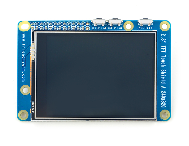
- The Matrix-2.8_SPI_Key_TFT LCD is a FriendlyARM developed LCD module with resistive touch panel. Its resolution is 240 x 320. It uses the ST7789S IC and XPT2046 resistive touch IC. It has SPI interface and three configurable user keys.
- Specification
| LCD Dimension | 2.8" |
| Display Area | 57.6mm*43.2mm |
| Driver IC | ST7789S |
| Resolution | 240 * 320(RGB) |
| MCU Interface | SPI |
| Power Supply | 5V |
| Backlight Voltage | 5V |
| Touch | Resistive Touch, tempered glass touch panel |
By default the module's backlight is turned on after the module is powered on. LED_EN can be set to turn off the backlight. If you don’t want the backlight to be turned on after the module is powered on you can take off R12 and in this case you can turn on the backlight by pulling up LED_EN.
2 Features
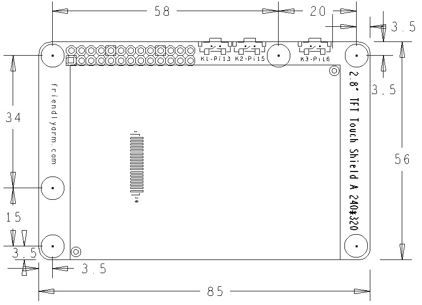
- PCB dimension(mm):
- Pin Description:
FriendlyElec has released two versions. Here are the spec:
| Matrix-2'8_SPI_Key_TFT-1706 | |||
| Pin# | Description | Pin# | Description |
| 1 | VDD_3.3V | 2 | VDD_5V |
| 3 | NC | 4 | VDD_5V |
| 5 | NC | 6 | GND |
| 7 | LCD_RESET | 8 | NC |
| 9 | GND | 10 | NC |
| 11 | LED_EN | 12 | T_CS |
| 13 | KEY_1 | 14 | GND |
| 15 | KEY_2 | 16 | KEY_3 |
| 17 | VDD_3.3V | 18 | T_IRQ |
| 19 | SPI_MOSI | 20 | GND |
| 21 | SPI_MISO | 22 | LCD_D/C |
| 23 | SPI_CLK | 24 | LCD_CS |
| 25 | GND | 26 | NC |
| Matrix-2'8_SPI_Key_TFT-1512 | |||
| Pin# | Description | Pin# | Description |
| 1 | VDD_3.3V | 2 | VDD_5V |
| 3 | NC | 4 | VDD_5V |
| 5 | NC | 6 | GND |
| 7 | LCD_RESET | 8 | NC |
| 9 | GND | 10 | NC |
| 11 | LED_EN | 12 | NC |
| 13 | KEY_1 | 14 | GND |
| 15 | KEY_2 | 16 | KEY_3 |
| 17 | VDD_3.3V | 18 | T_IRQ |
| 19 | SPI_MOSI | 20 | GND |
| 21 | SPI_MISO | 22 | LCD_D/C |
| 23 | SPI_CLK | 24 | LCD_CS |
| 25 | GND | 26 | T_CS |
The Matrix-2'8_SPI_Key_TFT-1706 exposes T_CS from Pin26 to Pin12. And NEO/NEO2/NEO-Plus2 all of which have a 24Pin connector will be able to work with its touch.
3 Applicable Boards & OS
| Index | SoC Model | Board Model | OS |
| 1 | H3 | NanoPi NEO/NEO Air/NEO Core/M1/M1 Plus | Allwinner's released Linux-3.4 kernel and Mainline Linux-4.x kernel |
| 2 | H5 | NanoPi NEO2/NEO Plus2/NEO Core2 | Mainline Linux-4.x kernel |
| 3 | S5P4418 | NanoPi2/NanoPi M2/NanoPi2 Fire | Samsung's released Linux-3.4 kernel |
4 Applications
4.1 H3 Based Boards
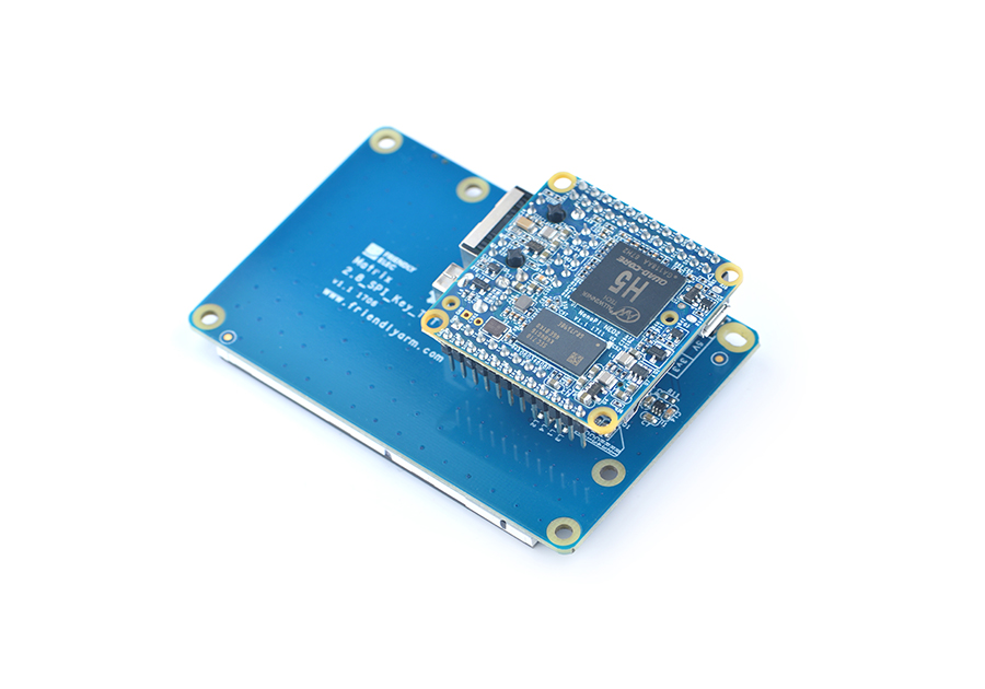
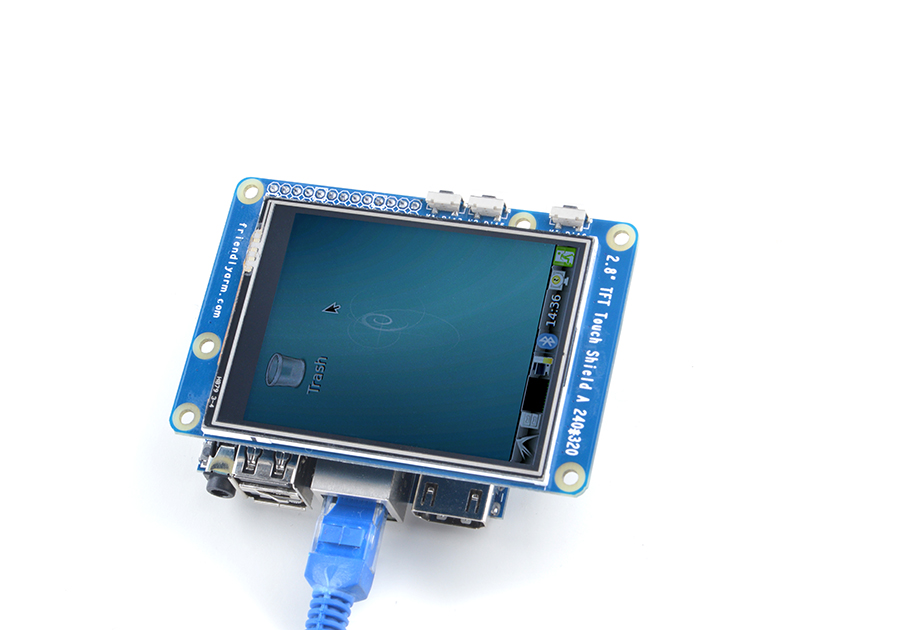
Connect to NanoPi M1:
Refer to the following hardware setup to connect the module to the NanoPi M1:
Connect to NanoPi M1 Plus:
Refer to the following hardware setup to connect the module to the NanoPi M1 Plus:
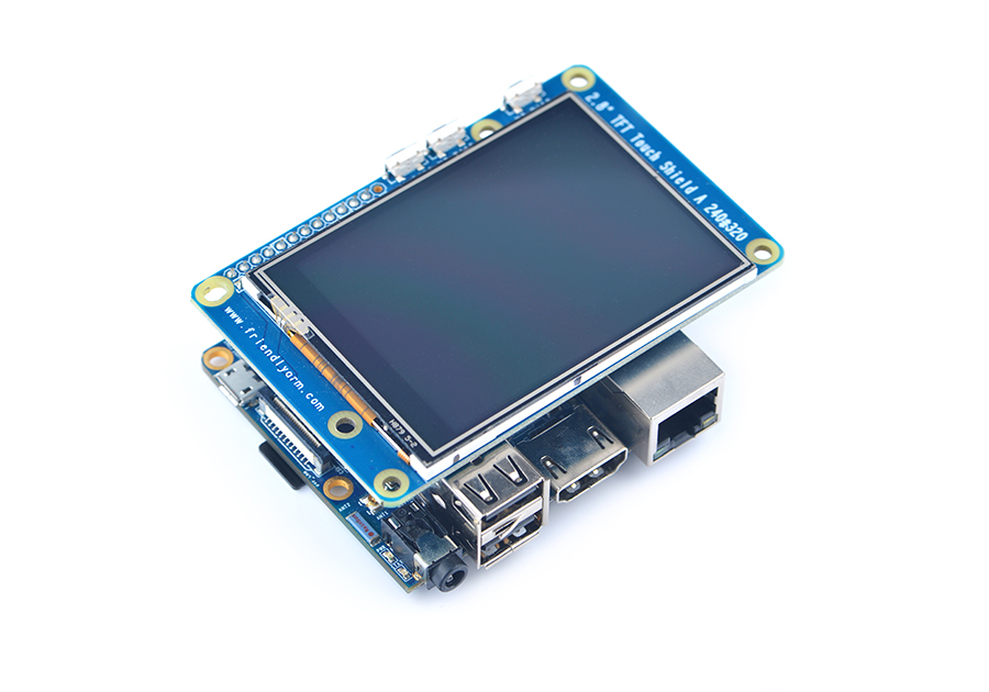
Connect to NanoPi NEO:
Refer to the following hardware setup to connect the module to the NanoPi NEO:
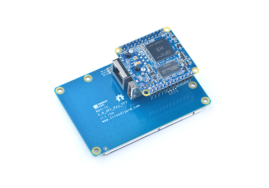
Connect to NanoPi NEO Air:
Refer to the following hardware setup to connect the module to the NanoPi NEO Air:
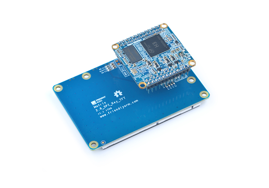
Connect to NanoPi NEO Core:
Refer to the following hardware setup to connect the module to the NanoPi NEO Core:
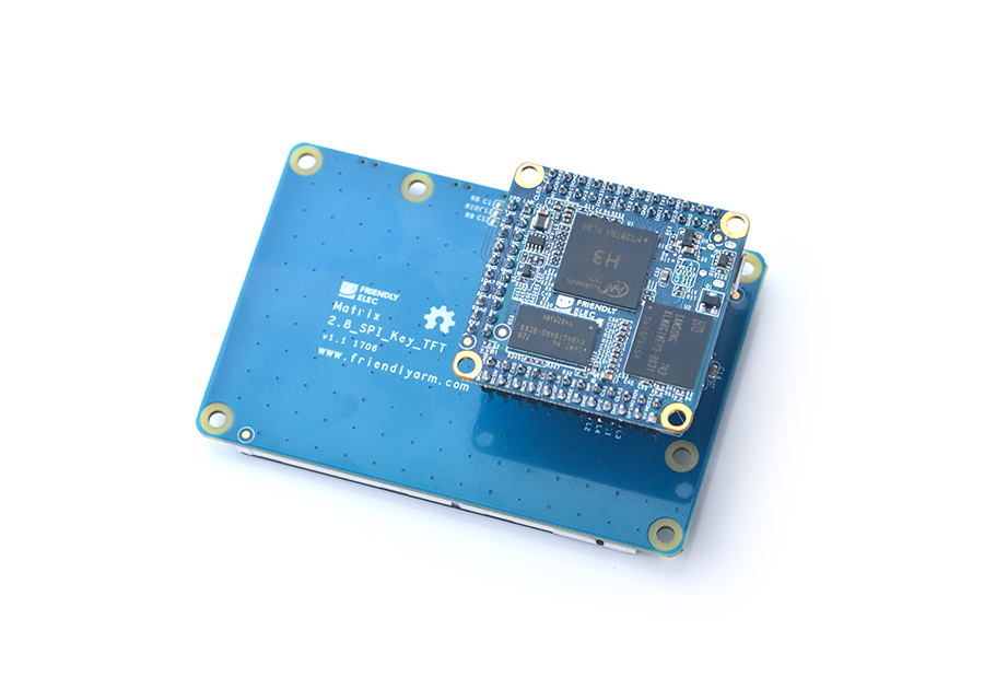
4.2 H5 Based Boards
Connect to NanoPi NEOPlus2:
Matrix-2'8_SPI_Key_TFT_nanopi_neo_plus2
Connect to NanoPi NEO Core2:
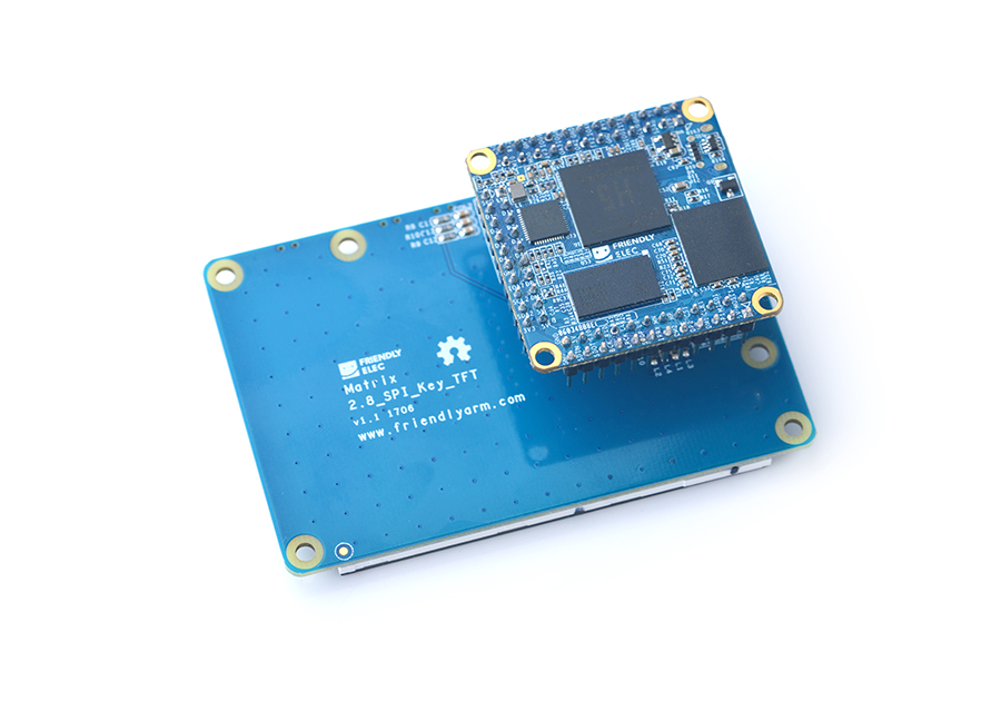
Refer to the following hardware setup to connect the module to the NanoPi NEO Core:
4.3 S5P4418 Based Boards
Connect to NanoPi 2:
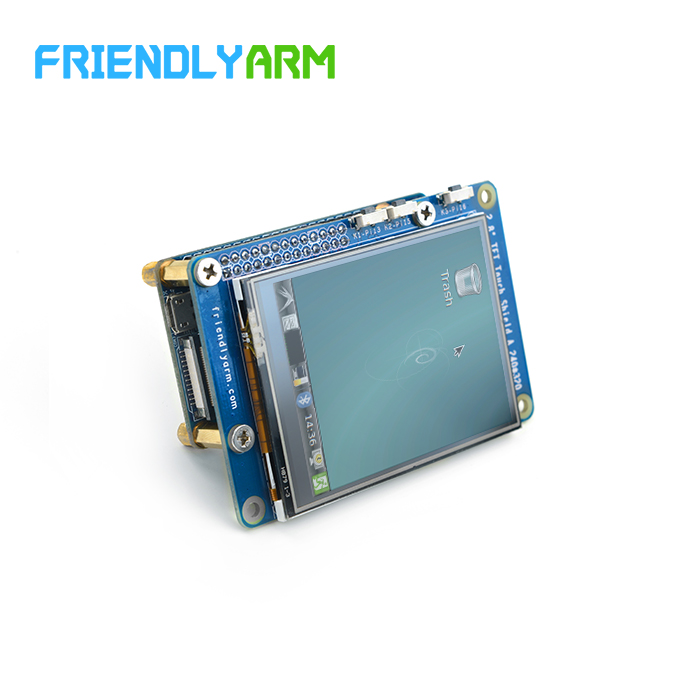
Refer to the following hardware setup to connect the module to the NanoPi 2:
Connect to NanoPi M2 / NanoPi 2 Fire:
Refer to the following hardware setup to connect the module to the NanoPi M2 / NanoPi 2 Fire:
Matrix-2'8_SPI_Key_TFT_nanopi_m2
5 Run pre-enabled Matrix-2'8_SPI_Key_TFT ROM
Board Type CPU Model Download Link to Image File Image File NanoPi NEO H3 Download official-ROMs/accessory-ROMs/nanopi-neo_sd_ubuntu-tft_4.14_YYYYMMDD.img.zip NanoPi NEO Air H3 Download official-ROMs/accessory-ROMs/nanopi-neo-air_sd_ubuntu-tft_4.14_YYYYMMDD.img.zip NanoPi M1 H3 Download official-ROMs/accessory-ROMs/nanopi-m1_sd_ubuntu-tft_4.14_YYYYMMDD.img.zip NanoPi M1 Plus H3 Download official-ROMs/accessory-ROMs/nanopi-m1-plus_sd_ubuntu-tft_4.14_YYYYMMDD.img.zip NanoPi NEO Core H3 Download official-ROMs/accessory-ROMs/nanopi-neo-core_sd_ubuntu-tft_4.14_YYYYMMDD.img.zip NanoPi NEO2 H5 Download official-ROMs/accessory-ROMs/nanopi-neo2_sd_ubuntu-tft_4.14_YYYYMMDD.img.zip NanoPi NEO Plus2 H5 Download official-ROMs/accessory-ROMs/nanopi-neo-plus2_sd_ubuntu-tft_4.14_YYYYMMDD.img.zip NanoPi NEO Core2 H5 Download official-ROMs/accessory-ROMs/nanopi-neo-core2_sd_ubuntu-tft_4.14_YYYYMMDD.img.zip NanoPi K1 Plus H5 Download official-ROMs/accessory-ROMs/nanopi-k1-plus_sd_ubuntu-tft_4.14_YYYYMMDD.img.zip
6 Compile & Run Test Program Manually
6.1 H3/H5
Note: the following method only applies for the Matrix-2'8_SPI_Key_TFT-1706 model. To test a Matrix-2'8_SPI_Key_TFT-1512(silkscreen T28-02 1512) refer to the last section and set Pin26 as the touch's enable/disable pin.
6.1.1 Linux-4.14
6.1.1.1 Use npi-config to enable 2.8"TFT
If you use a FriendlyElec's H3/H5 board under Mainline Linux-4.14 kernel you need to enable the 2.8"TFT with npi-config.Start npi-config as root:
$ npi-configOpen the following menu:
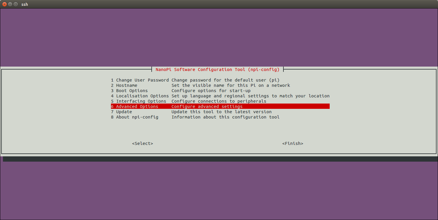
Open SPI:
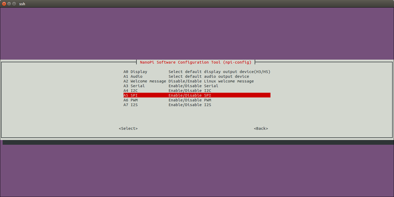
Enable/Disable SPI0:
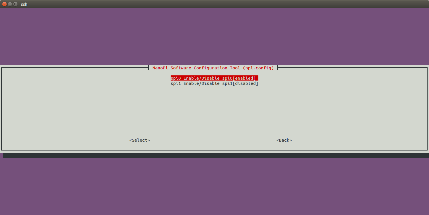
Enable SPI0 and then select Matrix-2.8"_SPI_Key_TFT:
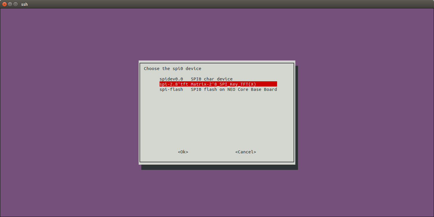
Return to the main menu and do <Finish>. Reboot your system and run the following command to check whether or not the Matrix-2.8"_SPI_Key_TFT is enabled:
$ ls /dev/fb-st7789s
/dev/fb-st7789s
/dev/fb-st7789s stands for a framebuffer device
$ ls /dev/input/ts-ads7846
/dev/input/ts-ads7846
/dev/input/ts-ads7846 stands for a touch device
When you first start the system you will be prompted to click on five points to do calibration.
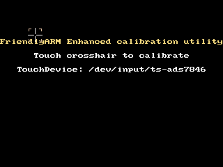
Note: in the mainline Linux-4.x kernel Pin12 of Matrix-2'8_SPI_Key_TFT-1706 is by default set as touch device's enable/disable pin.
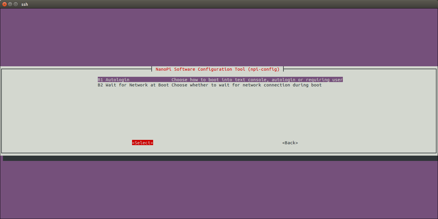
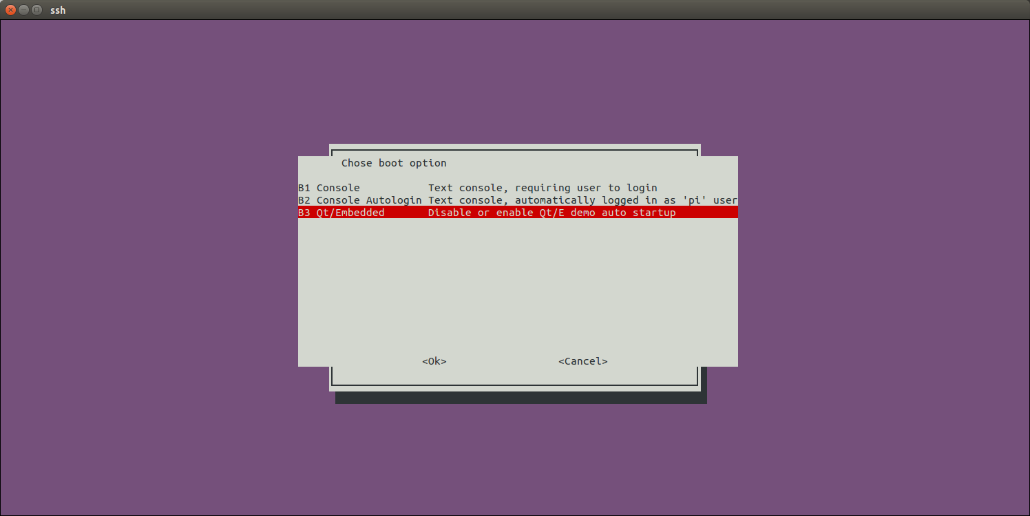
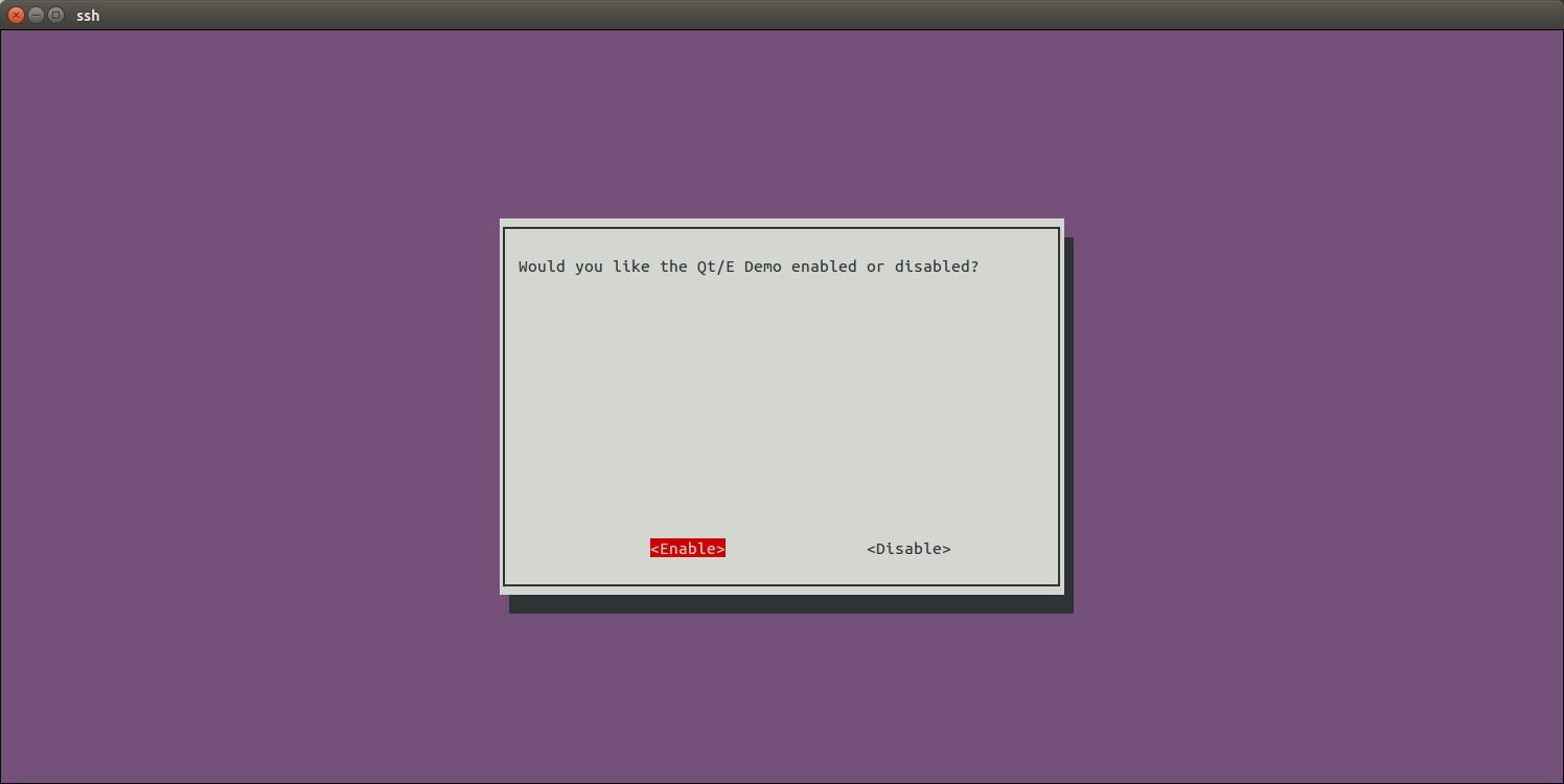
After you enable the Matrix-2'8_SPI_Key_TFT with npi-config your system will set it as your default display device. If you want to make Qt-demo auto-start on system boot you can follow the steps below:
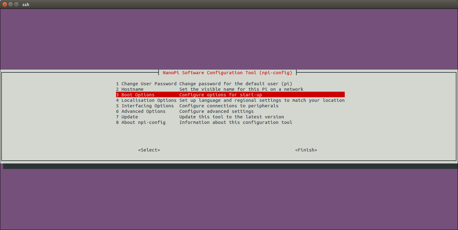
Enter Autologin:
Enter Qt/Embedded:
Enable Qt/E Demo:
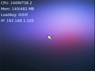
Return to the main menu and do <Finish>.Reboot your system and your Qt/E demo will be started automatically:
6.1.1.2 Control backlight
$ echo 1 >/sys/class/backlight/fb_st7789v/bl_power   # 关闭背光
$ echo 0 >/sys/class/backlight/fb_st7789v/bl_power   # 打开背光
6.1.1.3 Extra setup for Matrix-2'8_SPI_Key_TFT-1512
If you connect a Matrix-2'8_SPI_Key_TFT-1512(silkscreen T28-02 1512) to a NanoPi M1/NanoPi M1 Plus you need to make changes in the kernel code to set Pin26 as touch's enable/disable pin.
Compile your kernel by following the steps in Mainline U-boot & Linux and make the following changes:
$ vi linux/arch/arm/boot/dts/sun8i-h3-nanopi
    ...
    spi0_cs_pins: spi0_cs_pins {
        pins = "PC3", "PA6";
        function = "gpio_out";
    };
    ...
&spi0 {
    ...
    cs-gpios = <&pio 2 3 GPIO_ACTIVE_HIGH>, <&pio 0 6 GPIO_ACTIVE_HIGH>;
    ...
<&pio 0 6 GPIO_ACTIVE_HIGH> means setting GPIOA6(Pin12) as touch's enable/disable pin. Change it to GPIOA17(Pin26):
    ...
    spi0_cs_pins: spi0_cs_pins {
        pins = "PC3", "PA17";
        function = "gpio_out";
    };
    ...
&spi0 {
    ...
    cs-gpios = <&pio 2 3 GPIO_ACTIVE_HIGH>, <&pio 0 17 GPIO_ACTIVE_HIGH>;
    ...
Recompile the kernel code and copy the "sun8i-h3-nanopi-m1.dtb/sun8i-h3-nanopi-m1-plus.dtb" file under arch/arm/boot/dts/ to your TF card's boot section and reboot your board.
6.2 S5P4418/S5P6818
The following steps only apply to Kernel Linux-4.4. We took the NanoPi Fire3 as an example. Run the following commands to initialize FriendlyElec's 2.8" SPI LCD. These commands need to be run only once.
sudo mount /dev/mmcblk0p1 /boot
sudo apt-get update
sudo apt-get install device-tree-compiler
sudo fdtput /boot/s5p6818-nanopi3-rev05.dtb spi0/spidev@0 status -t s "disabled"
sudo fdtget /boot/s5p6818-nanopi3-rev05.dtb spi0/spidev@0 status
sudo fdtput /boot/s5p6818-nanopi3-rev05.dtb spi0/fbtft@0 status -t s "okay"
sudo fdtget /boot/s5p6818-nanopi3-rev05.dtb spi0/fbtft@0 status
sudo reboot
Note: the "s5p6818-nanopi3-rev05.dtb" file is the kernel dtb file for the NanoPi Fire3. For another board you need to check its system's "/sys/devices/platform/board/info" file to figure out its dtb file.:
cat /sys/devices/platform/board/info
Here is the info file's content for the NanoPi Fire3:
Hardware : NANOPI3
Revision : 0005
Serial : fa6818dba7110739
The "Hardware" here is "NANOPI3", "Revision" is "0005", "CPU" is "S5P6818", therefore the NanoPi Fire3's kernel dtb file name is "s5p6818-nanopi3-rev05.dtb".
After the dtb file is confirmed you can reboot your board and run the following command to check if the fb_st7789v module is loaded:
lsmodHere is what you expect to see:
Module Size Used by
fb_st7789v 3315 0
fbtft 31881 1 fb_st7789v
Or you can run dmesg to check that. In our case after we ran dmesg we found that the SPI LCD was recognized as an "fb1" device:
dmesg | grep fb_st7789v
Here is what you expect to see:
[ 6.728000] fb_st7789v: module is from the staging directory, the quality is unknown, you have been warned.
[ 6.908000] graphics fb1: fb_st7789v frame buffer, 320x240, 150 KiB video memory, 4 KiB buffer memory, fps=35, spi0.0 at 50 MHz
Now as long as you set your system's framebuffer device to fb1 in either Qt or X-Windows you will see output in your LCD.
6.2.1 Launch Lubuntu Desktop on 2.8"LCD
On lubuntu desktop run the following commands:
Firstly remove the armsoc configuration file:
sudo rm -f /usr/share/X11/xorg.conf.d/20-armsoc.conf
Secondly create a new configuration file /etc/X11/xorg.conf:
sudo vi /etc/X11/xorg.conf
Here is its content:
Section "Monitor"
    Identifier          "Primary"
    VendorName          "FriendlyARM"
EndSection

Section "Device"
    Identifier          "Primary"
    Driver              "fbdev"
    Option              "fbdev" "/dev/fb1"
EndSection
After reboot you will see the following GUI:
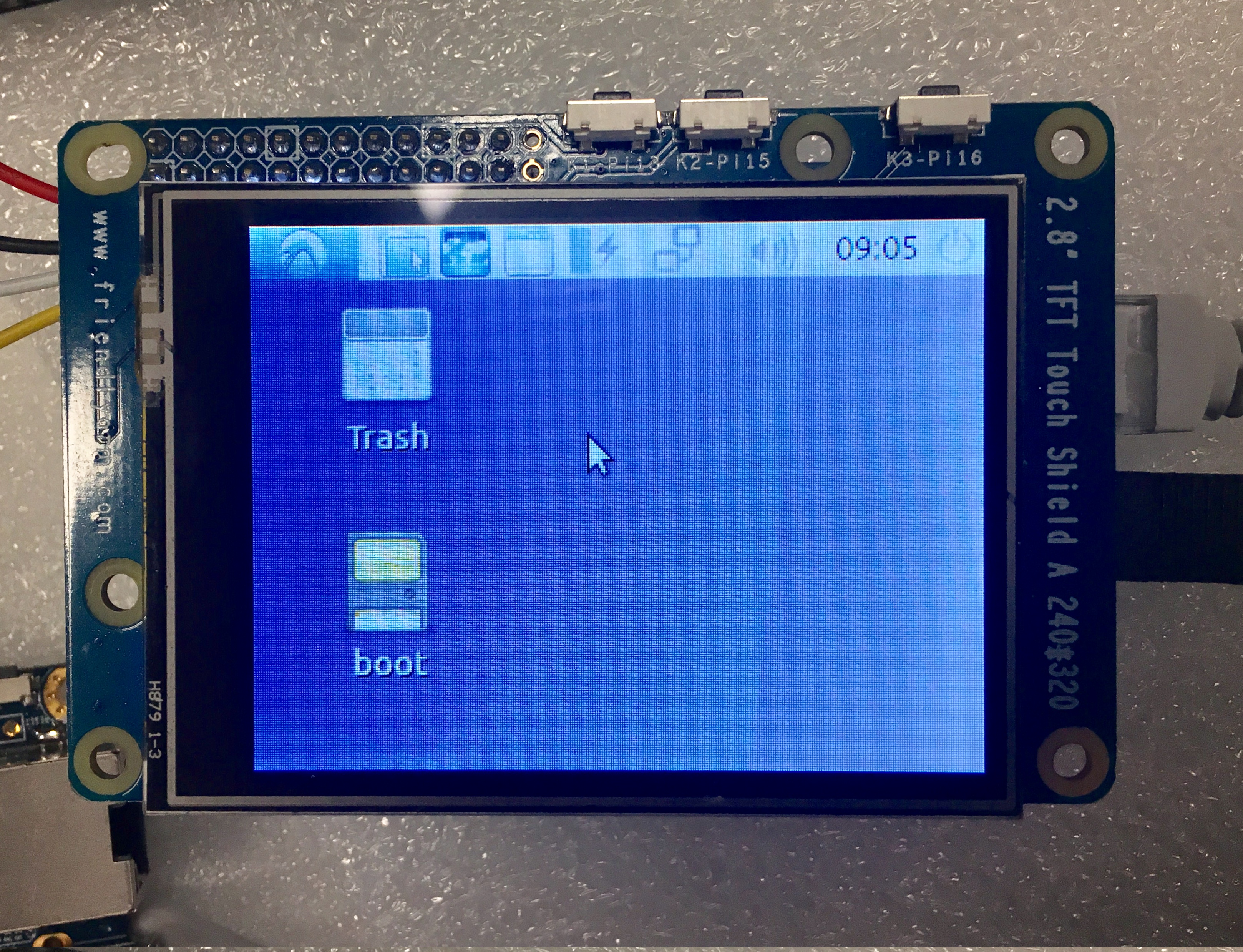
A touch panel is currently not supported yet. You need to use a mouse and keyboard to operate.
6.2.2 Run Qt Application on 2.8"LCD
Open a terminal in friendly-core and run the following commands to start a Qt demo:
. setqt5env
export QT_QPA_PLATFORM=linuxfb:fb=/dev/fb1
export QT_QPA_EGLFS_TSLIB=1
export QT_QPA_GENERIC_PLUGINS=tslib,evdevkeyboard
$QTDIR/examples/widgets/widgets/tetrix/tetrix
Here is a Qt demo:
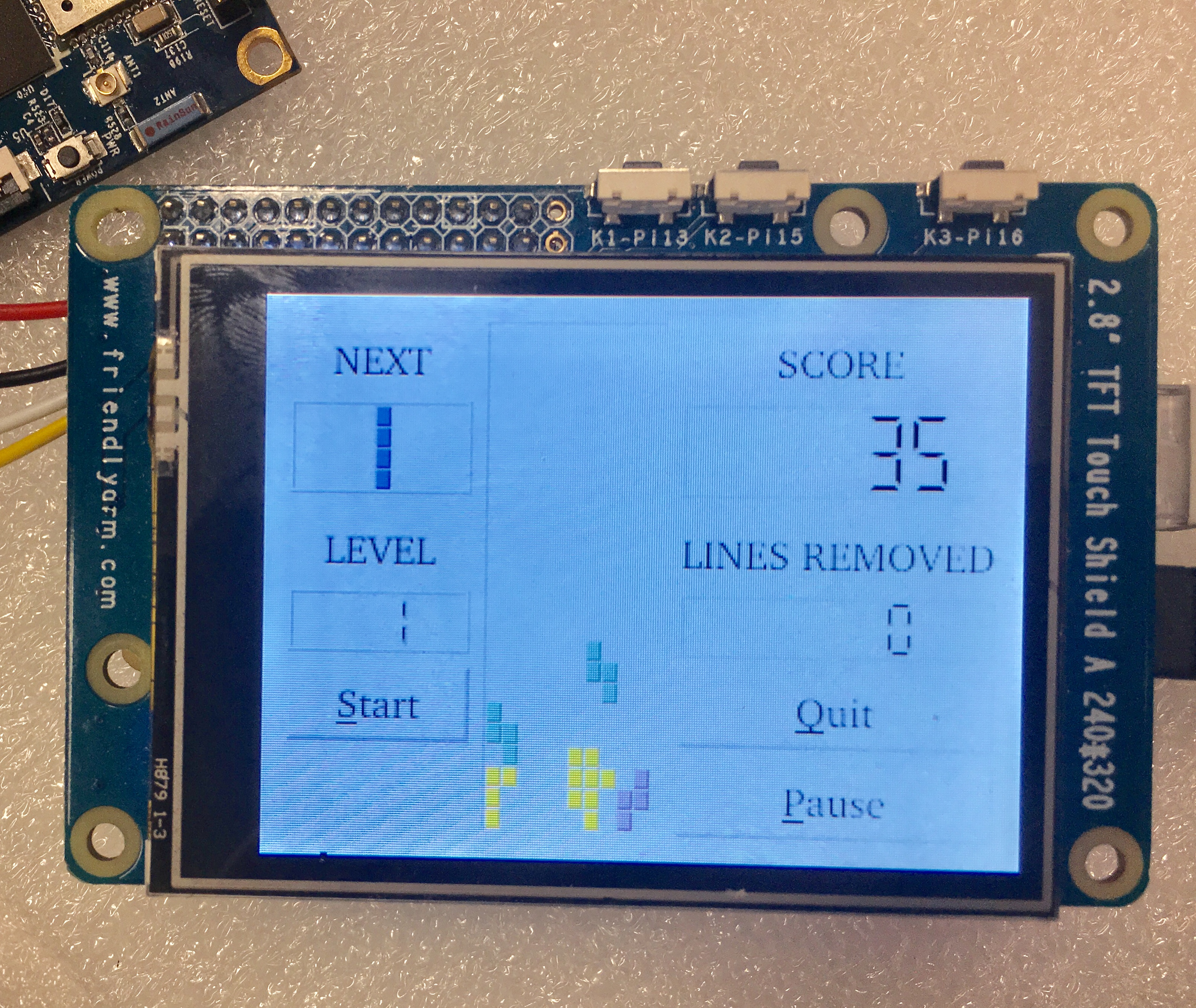
A touch panel is currently not supported yet. You need to use a mouse and keyboard to operate.
7 Update Log
7.1 Dec-15-2017
- Released English version
8 Resources
9 Update Log
9.1 Feb-24-2016
- Added the driver's source code location in Section 5.2
9.2 June-17-2016
- Re-organized and simplified wiki
9.3 March-5-2017
- Added sections 3.2, 3.3, 3.4 and 4.1
9.4 July-5-2017
- Updated sections 4 and 5
9.5 July-15-2017
- Updated section 5
