Difference between revisions of "Matrix - I2C LCD1602"
From FriendlyELEC WiKi
(→PCF8574) |
(→LCD1602) |
||
| Line 26: | Line 26: | ||
===LCD1602=== | ===LCD1602=== | ||
| + | *The PCF8574 module's P0 - P7's pin spec are as follows: | ||
*由模块的原理图可以看出PCF8574模块的输出引脚P0-P7与LCD模块的引脚连接如下图: | *由模块的原理图可以看出PCF8574模块的输出引脚P0-P7与LCD模块的引脚连接如下图: | ||
[[File:1602.png|frameless|400px|1602]] | [[File:1602.png|frameless|400px|1602]] | ||
| + | *RS is command/data, RW is read/write, E is Enable(), BL is backlight and D4-D7 are data bits. | ||
*RS为指令/数据控制位,RW为读/写控制位,E为使能位(边沿触发),BL为背光灯控制位,D4-D7为数据位。 | *RS为指令/数据控制位,RW为读/写控制位,E为使能位(边沿触发),BL为背光灯控制位,D4-D7为数据位。 | ||
*由于LCD用到四个数据位,因此只能使用4线来驱动。通过指令表我们可以对LCD进行写指令设置LCD的工作转态,但这里的指令/数据(DB7-DB0)是八位的,而LCD却是4线驱动,因此每次写指令/数据时是先写高四位(DB7-DB4),再写低四位(DB3-DB0)。 | *由于LCD用到四个数据位,因此只能使用4线来驱动。通过指令表我们可以对LCD进行写指令设置LCD的工作转态,但这里的指令/数据(DB7-DB0)是八位的,而LCD却是4线驱动,因此每次写指令/数据时是先写高四位(DB7-DB4),再写低四位(DB3-DB0)。 | ||
Revision as of 08:27, 17 August 2015
Contents
1 Introduction
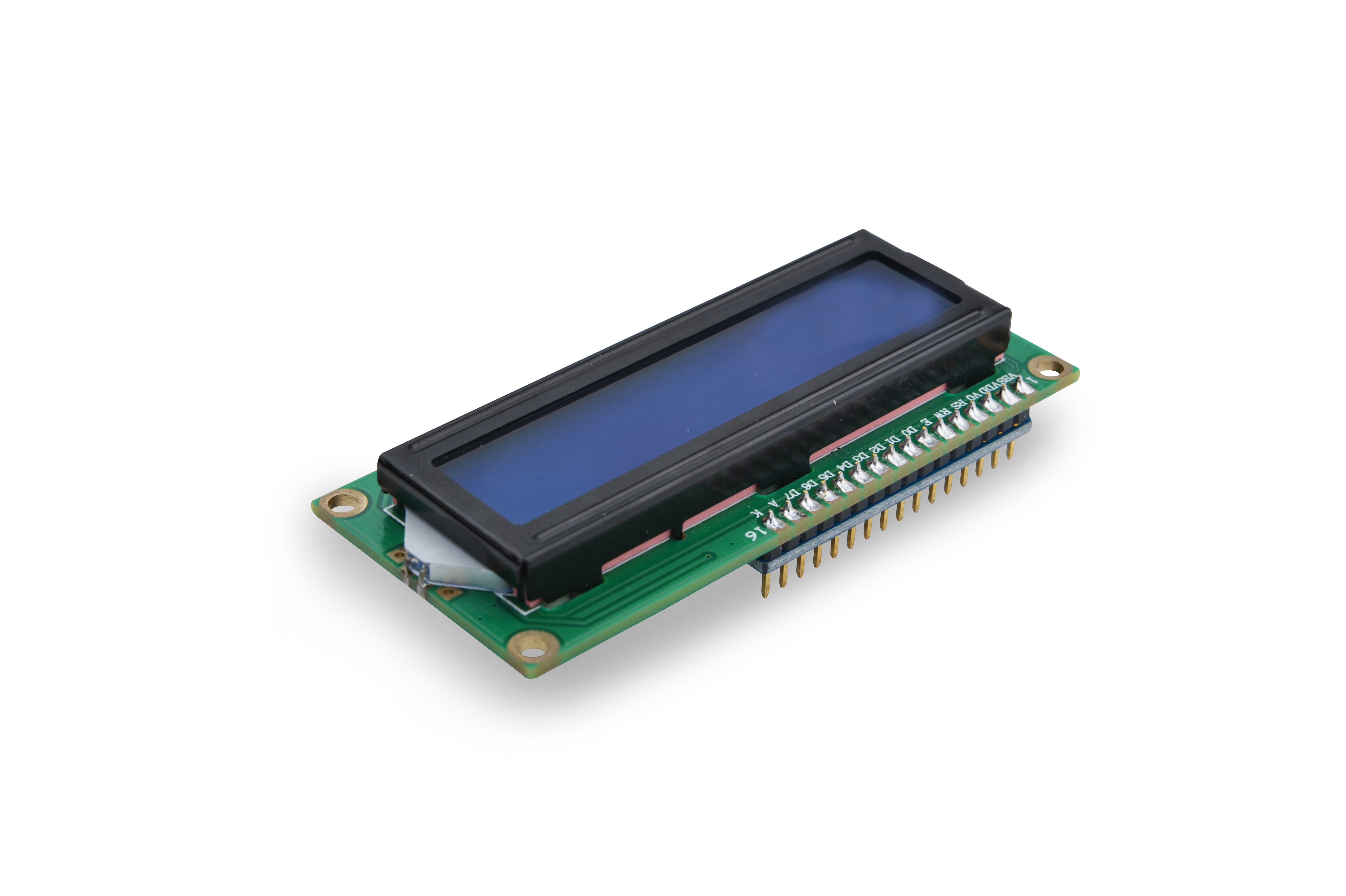
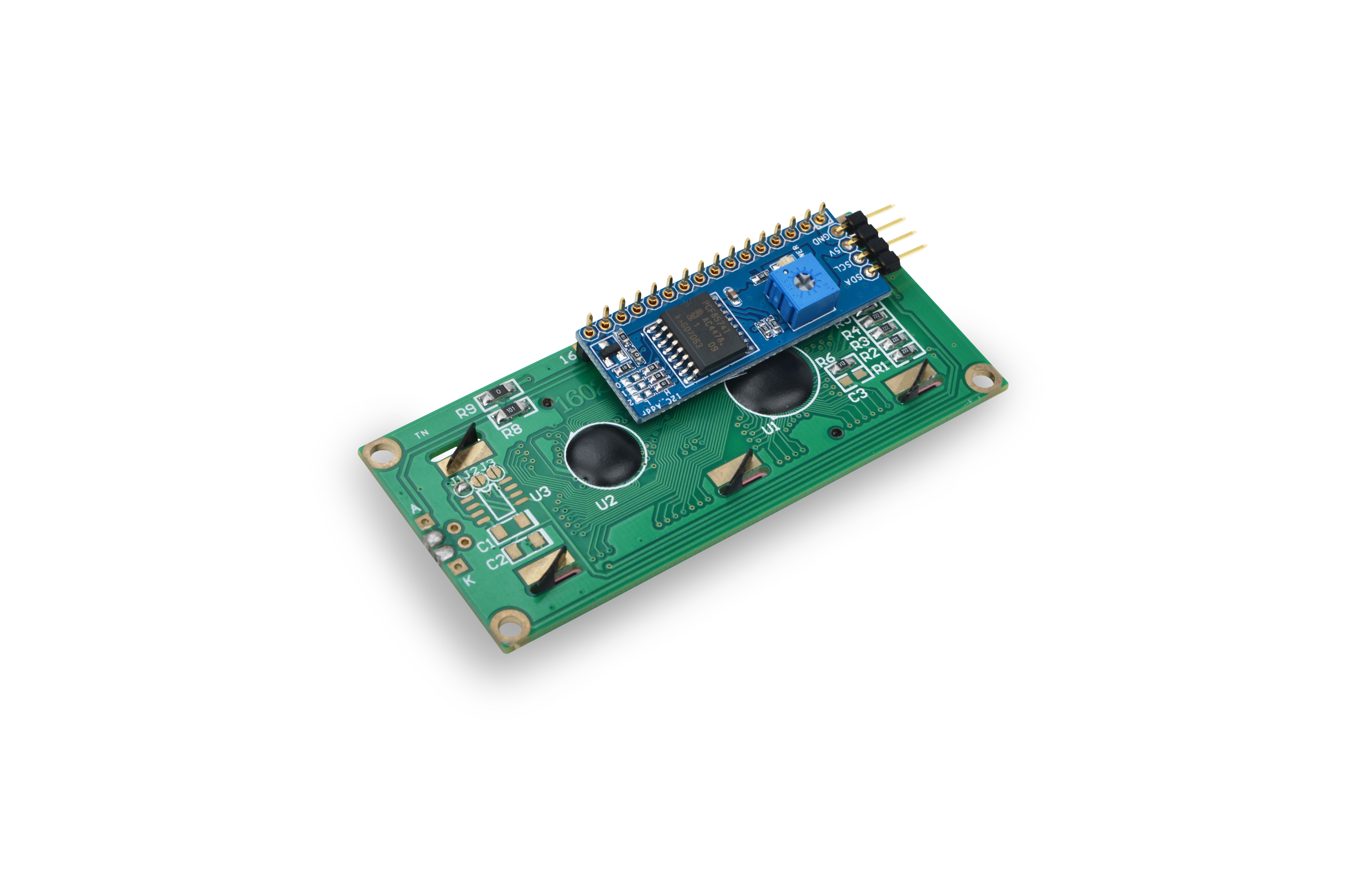
This is an LCD module which has an I2C controller. It can display 16 x 2 characters. Its interface is parallel. To simplify its application we designed a controller on this module, which interfaces with other modules through I2C and transfers received signals to parallel signals to LCD1602. It can display, turn on and off back light.
2 Features
- I2C interface. It can display characters, and turn on and off back light
- 2.54 mm spacing pin
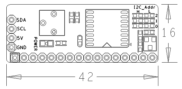
- I2C PCB dimension:16 x 42 mm
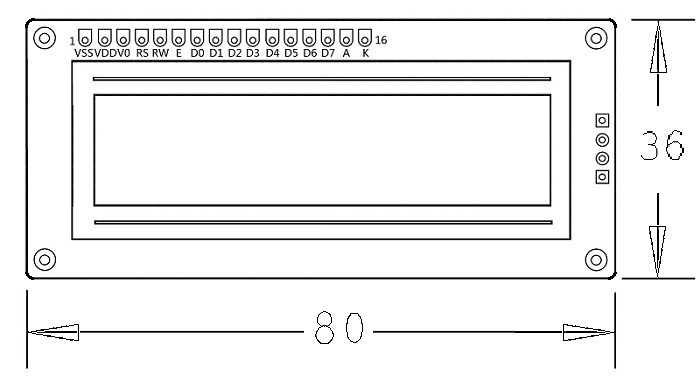
- LCD1602 PCB dimension: 36 x 80 mm
3 How They Work
3.1 PCF8574
- The PCF8574 module's interface is I2C parallel which is 8 bit and has 8 IO (P0 - P7) outputs.
- The PCF8574 module uses the PCF8574T chip whose address diagram is as follows:
- If you set A2-A0 all to "1" the address will be 0x27(0100111). By default RW is "0" and the module is in the "write" mode.
- If it is in the write mode and the address is set you can open "i2c-0" and write data to it.
- If you want to set it to "read" (RW set to "1") please refer to PCF8574's datasheet for more details
3.2 LCD1602
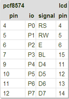
- The PCF8574 module's P0 - P7's pin spec are as follows:
- 由模块的原理图可以看出PCF8574模块的输出引脚P0-P7与LCD模块的引脚连接如下图:
- RS is command/data, RW is read/write, E is Enable(), BL is backlight and D4-D7 are data bits.
- RS为指令/数据控制位,RW为读/写控制位,E为使能位(边沿触发),BL为背光灯控制位,D4-D7为数据位。
- 由于LCD用到四个数据位,因此只能使用4线来驱动。通过指令表我们可以对LCD进行写指令设置LCD的工作转态,但这里的指令/数据(DB7-DB0)是八位的,而LCD却是4线驱动,因此每次写指令/数据时是先写高四位(DB7-DB4),再写低四位(DB3-DB0)。
- 注意:LCD内置了192个常用字模,存放在CGROM,所以我们在显示字符A时可以直接写入“A”,此外LCD还有8个允许用户自定义的字符产生的RAM,称为CGRAM,这里由于没有涉及到所以不介绍,有兴趣的用户可以去了解一下。
4 How To
4.1 Connection
- Connect to Tiny4412 SDK (1506)
- GND: Ground
- VCC: 5V
- SDA: I2C SDA
- SCL: I2C SCL
4.2 Code Sample in C Under Linux
#include <stdio.h>
#include <unistd.h>
#include <sys/types.h>
#include <sys/stat.h>
#include <fcntl.h>
#include <stdlib.h>
#include "libfahw.h"

void test(char* line1, char* line2)
{
    int devFD;
    if ((devFD = LCD1602Init()) == -1) {
        printf("Fail to init LCD1602\n");
        return;
    }

            if (LCD1602Clear(devFD) == -1) {
                    printf("Fail to Clear\n");
                    return;
            }

    if (LCD1602DispLines(devFD, line1, line2) == -1) {
        printf("Fail to Display String\n");
        return ;
    }

    LCD1602DeInit(devFD);
}

int main(int argc, char ** argv) {
    int i;
    for (i=0; i<10; i++) {
         test("FriendlyARM", "From 2003");
         sleep(3);
    }
    return 0;
}
4.3 Compile and Run
git clone http://github.com/friendlyarm/fa-hardware.git
cd fa-hardware
cd demo
cd matrix-i2c_lcd1602
make
Copy your compiled bin to your board and you are ready to go.
