Smart4418 SDK
From FriendlyELEC WiKi
1 Introduction


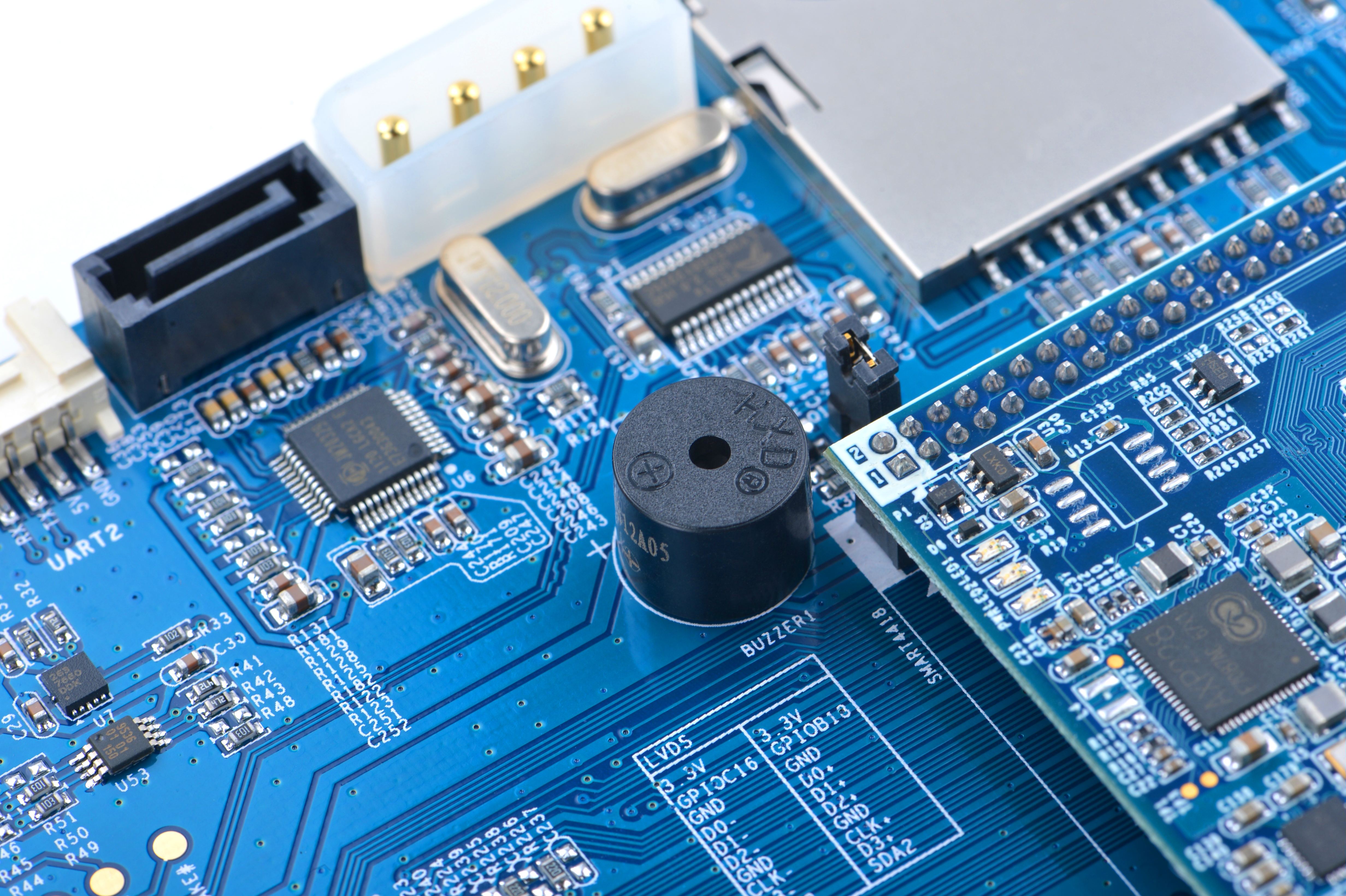
- The Smart4418 SDK carrier board V1606 has various interfaces and ports like HDMI port, USB host, SD card slot, SB9 serial port, RJ-45 Ethernet port, 3.5mm audio jack, SATA interface, MiniPCIe, MicroSIM etc with support for 3G/4G Bluetooth & WiFi.In addition it has hardware resources like buzzer, user keys, RTC battery, microphone and etc for users to evaluate its performance and features. FriendlyARM designed it for sake of industrial applications by putting all commonly used interfaces and ports on one side with mounting holes for easy deployment.
- To make this carrier board applicable in various applications compared to our existing carrier boards we add more interfaces and ports such as DVP camera interface, SPI, GPIO, I2C, AP6212 WiFi & Bluetooth module, porcelain antenna, RTC seat and etc.
2 资源特性

SDK Carrier Board Model Smart4418SDK 1606 Dimension 189.8 x 118.2(mm) Applicable CPU Board Smart4418 WiFi/Bluetooth Onboard WiFi & Bluetooth MiniPCIe Interface For 4G modules, data service only, speech service not applicable SIM Card Slot Pop-up MicroSIM card slot Antenna Onboard porcelain antenna DVP Camera Interface 24pin, 0.5mm pitch FPC seat
DVP Camera interface, ITU-R BT 601/656 8-bitHDMI Interface 1 x HDMI A Type, HDMI 1.4a (Smart4418)
1080p30 video outputRS232 Serial Interface 2 x 3-wire serial port (UART0 and 3), DB9 male connector USB Host 2 x USB A
brought out from USB 2.0 hub, (USB 1.1 compatible)USB Slave 1 x Micro USB, data communication only Audio Interface Internal Audio
supports audio recording and play
3.5mm audio jack and MIC
onboard Microphone以太网 直接引出核心板资源,1000/100/10M自适应 按键 PWRKEY(电源按键)
RST(重启按键)
K1/K2/K3可独立编程按键LED 2个GPIO控制可编程LED(位于核心板) RTC 板载RTC电池(CR1220) 蜂鸣器 1路PWM控制蜂鸣器输出 SPI扩展接口 CON3: 26pin ,2.54mm双排针 GPIO座子 GPIOC9、GPIOC10、GPIOC11、GPIOC12 SD卡座 弹出式SD卡座 I2C扩展接口 I2C0 UART串口接口 UART2 SATA接口 板载SATA接口 SATA电源接口 板载SATA电源接口 LCD接口 LCD接口座(45pin, 0.5mm间距FPC贴片座)
支持一线触摸
支持背光可调
支持电容触摸屏
支持RGB888模式
支持全彩TFT CDLCD固定孔 适用于X710 LCD模块 LVDS接口 2pin, 2.0mm间据 GPIO接口 30pin 2.0mm双排针, 包含1个UART, 1个I2C, 1个SPI, 1路SDIO, 11个GPIO 其它 板载1个EEPROM, 1个三轴加速度传感器 供电 DC 9V~24V/2A, 当使用SATA或LVDS背光时, 必须12V/3A供电
3 接口描述和尺寸
3.1 接口描述
- LVDS接口
Pin# Name Pin# Name 1 SYS_3.3V 2 SYS_3.3V 3 GPIOC16 4 GPIOB18 5 DGND 6 DGND 7 LVDS_D0- 8 LVDS_D0+ 9 LVDS_D1- 10 LVDS_D1+ 11 LVDS_D2- 12 LVDS_D2+ 13 DGND 14 DGND 15 LVDS_CLK- 16 LVDS_CLK+ 17 LVDS_D3- 18 LVDS_D3+ 19 I2C2_SCL 20 I2C2_SDA
- DVP摄像头接口
Pin# Name 1, 2 SYS_3.3V 7,9,13,15,24 DGND 3 I2C0_SCL 4 I2C0_SDA 5 GPIOB14 6 GPIOB16 8,10 NC 11 VSYNC 12 HREF 14 PCLK 16-23 Data bit7-0
- LCD接口
Pin# Name Description 1, 2 VDD_5V 5V输出, 可以给LCD模组供电 11,20,29, 37,38,39,40, 45 DGND 参考地, 0电位 3-10 Blue LSB to MSB RGB的蓝色信号 12-19 Green LSB to MSB RGB的绿色信号 21-28 Red LSB to MSB RGB的红色信号 30 GPIOB25 普通GPIO, 用户可控制 31 GPIOC15 一线协议信号, 以实现LCD型号识别,
背光控制和电阻触摸的功能. 系统已占用, 用户不可重新设置.
32 XnRSTOUT Form CPU 系统复位时向外输出低电平 33 VDEN 指示RGB信号有效的信号 34 VSYNC 场信号 35 HSYNC 行信号 36 LCDCLK LCD频率, Pixel frequency 41 I2C2_SCL I2C2的时钟信号, 用来传输电容屏触摸数据 42 I2C2_SDA I2C2的数据信号, 用来传输电容屏触摸数据 43 GPIOC16 电容触摸中断信号, 配合I2C2使用 44 NC 没有任何连接
- SATA接口
- 标准7Pin数据接口, 大4Pin电源接口

- 电源接口
- DC电源座子, 适合DC5.5*2.1mm电源插头, 9V~24V宽电压输入, 因为SATA电源和LVDS背光电源跟输入电源直接连通, 所以当使用SATA或LVDS背光时, 必须12V/3A供电
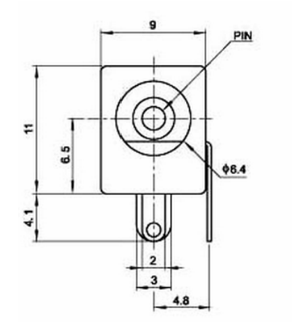

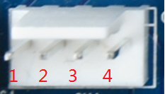
- 2.54mm间距, 2510-4P针座. Pin1~Pin4定义: VDD_12V, DGND, DGND, 12V_IN
其中12V_IN直接连到DC电源座子, VDD_12V是5V_IN经过开关S1后连接到板子的12V电源网络
- 2.54mm间距, 2510-4P针座. Pin1~Pin4定义: VDD_12V, DGND, DGND, 12V_IN

3.2 机械尺寸

- 详细尺寸:dxf文件
4 资源链接
- SDK硬件设计文件
- Smart4418核心板软件和硬件详细介绍
- Smart4418原理图pdf