NanoPC-T4
Contents
- 1 Introduction
- 2 Hardware Spec
- 3 Software Features
- 4 Diagram, Layout and Dimension
- 5 Get Started
- 6 Work with Android7
- 7 Work with FriendlyCore
- 8 Work with Lubuntu
- 9 Make Your Own OS Image
- 10 More OS Support
- 11 Link to Rockchip Resources
- 12 Update Log
1 Introduction


- The NanoPC-T4 is by far the smallest RK3399 based high-performance ARM board with popular ports and interfaces. Its software is fully open source. It is as small as 100 x 64 mm. It has 4GB LPDDR3 RAM, 16GB eMMC flash, onboard 2.4G & 5G dual-band WiFi module and a full standard M.2 PCIe interface which supports an NVME SSD high-speed hard drive. The NanoPC-T4 supports GPU and VPU acceleration and works with Android 7.1 and Lubuntu Desktop.
- The NanoPC-T4 has a MIPI-CSI dual camera interface, a MIPI-DSI and an eDP display interfaces, and an HDMI 2.0 interface. It has Type-C/DP, USB 3.0, USB2.0, MicroSD, Gbps Ethernet port, 3.5mm audio jack, infrared receiver, AD input, serial debug interface and a 40Pin RPi compatible connector.
- The RK3399 SoC has an internal Mali-T860 GPU which has powerful capabilities of processing 3D and HD H.265/H2.64 video streams. It supports dual camera inputs, dual ISP interface capable of doing image processing up to 13MPix/s. The NanoPC-T4 is a perfect platform for AI and deep learning applications. It can be widely used in advertisement machines, game machines, video conference applications, surveillance systems, clusters, VR/AR applications, machine vision applications and etc.
2 Hardware Spec
- SoC: Rockchip RK3399
- CPU: big.LITTLE,Dual-Core Cortex-A72(up to 2.0GHz) + Quad-Core Cortex-A53(up to 1.5GHz)
- GPU: Mali-T864 GPU,supports OpenGL ES1.1/2.0/3.0/3.1, OpenVG1.1, OpenCL, DX11, and AFBC
- VPU: 4K VP9 and 4K 10bits H265/H264 60fps decoding, Dual VOP, etc
- PMU: RK808-D PMIC, cooperated with independent DC/DC, enabling DVFS, solfware power-down, RTC wake-up, system sleep mode
- RAM: Dual-Channel 4GB LPDDR3-1866
- Flash: 16GB eMMC 5.1 Flash
- Ethernet: Native Gigabit Ethernet
- Wi-Fi/BT: 802.11a/b/g/n/ac, Bluetooth 4.1, Wi-Fi and Bluetooth combo module, dual antenna interface
- Video Input: one or two 4-Lane MIPI-CSI, dual ISP, up to 13MPix/s,supports simultaneous input of dual camera data
- Video output
- HDMI: HDMI 2.0a, supports 4K@60Hz,HDCP 1.4/2.2
- DP on Type-C: DisplayPort 1.2 Alt Mode on USB Type-C
- LCD Interface: one eDP 1.3(4-Lane,10.8Gbps), one or two 4-Lane MIPI-DSI
- Audio Out: 3.5mm Dual channel headphone jack, or HDMI
- Audio In: Onboard microphone
- USB 2.0: 2 independent native USB 2.0 Host A interfaces
- USB 3.0: 1 native USB 3.0 Host A type interface
- USB Type-C: Supports USB3.0 Type-C and DisplayPort 1.2 Alt Mode on USB Type-C
- PCIe: One M.2 M-Key PCIe x4 socket, compatible with PCIe 2.1, Dual operation mode; Onboard M3 PCB nut for mounting M.2 2280 module
- microSD Slot x 1
- 40Pin GPIO Extension ports:
- 3 X 3V/1.8V I2C, up to 1 x 3V UART, 1 X 3V SPI, 1 x SPDIF_TX, up to 8 x 3V GPIOs
- 1 x 1.8V I2S, 3 x 1.8V GPIOs
- ADC: 3 x 1.8V ADC inputs, 5 Pin 2.54mm header
- Debug: one Debug UART, 4 Pin 2.54mm header, 3V level, 1500000bps
- Keys: PowerKey, Reset, MASKROM(BOOT), Recovery
- LED: 1 x power LED and 1 x GPIO Controlled LED
- IR reciver: Onboard IR reciver, Acceptes 38KHz carrier frequency
- RTC Battery: 2 Pin 1.27/1.25mm RTC battery input connector
- Cooling: two 2.5mm PCB nuts for mounting heat sink; 3 Pin 12V cooling fan interface with PWM
- Power supply: DC 12V/2A
- PCB: Ten Layer, 100 mm x 64 mm
- Ambient Operating Temperature: 0℃ to 80℃
3 Software Features
4 Diagram, Layout and Dimension
4.1 Layout

- 40 Pin GPIO Pin Spec
Pin# Assignment Pin# Assignment 1 VCC3V3_SYS 2 VCC5V0_SYS 3 I2C2_SDA(3V) 4 VCC5V0_SYS 5 I2C2_SCL(3V) 6 GND 7 GPIO1_A0(3V) 8 GPIO4_C1/I2C3_SCL(3V) 9 GND 10 GPIO4_C0/I2C3_SDA(3V) 11 GPIO1_A1(3V) 12 GPIO1_C2(3V) 13 GPIO1_A3(3V) 14 GND 15 GPIO1_A4(3V) 16 GPIO1_C6(3V) 17 VCC3V3_SYS 18 GPIO1_C7(3V) 19 SPI1_TXD/UART4_TX(3V) 20 GND 21 SPI1_RXD/UART4_RX(3V) 22 GPIO1_D0(3V) 23 SPI1_CLK(3V) 24 SPI1_CSn0(3V) 25 GND 26 GPIO4_C5/SPDIF_TX(3V) 27 I2C2_SDA(1.8V) 28 I2C2_SCL(1.8V) 29 I2S1_LRCK_RX(1.8V) 30 GND 31 I2S1_LRCK_TX(1.8V) 32 I2S_CLK(1.8V) 33 I2S1_SCLK(1.8V) 34 GND 35 I2S1_SDI0(1.8V) 36 I2S1_SDO0(1.8V) 37 GPIO3_D4(1.8V) 38 GPIO3_D5(1.8V) 39 GND 40 GPIO3_D6(1.8V)
- eDP Interface Pin Spec
- Connector P/N: I-PEX-20455-030E
Pin# Assignment Description 1 GND Signal ground 2 EDP_TX3N eDP data lane 3 negative output 3 EDP_TX3P eDP data lane 3 positive output 4 GND Signal ground 5 EDP_TX2N eDP data lane 2 negative output 6 EDP_TX2P eDP data lane 2 positive output 7 GND Signal ground 8 EDP_TX1N eDP data lane 1 negative output 9 EDP_TX1P eDP data lane 1 positive output 10 GND Signal ground 11 EDP_TX0N eDP data lane 0 negative output 12 EDP_TX0P eDP data lane 0 positive output 13 GND Signal ground 14 EDPAUXP eDP CH-AUX positive differential output 15 EDPAUXN eDP CH-AUX negative differential output 16 GND Signal ground 17 VCC3V3_SYS 3.3V Power output for logic 18 VCC3V3_SYS 3.3V Power output for logic 19 I2C4_SDA 3V I2C data signal, Connect to touch panel 20 I2C4_SCL 3V I2C clock signal, Connect to touch panel 21 GPIO1_C4_TP_INT 3V interrupt input, Connect to the interrupt output of touch panel 22 GPIO1_B5_TP_RST 3V output for reseting touch panel, Connect to the reset input of touch panel 23 PWM0_BL 3V PWM output, for LCD backlight dimming 24 GPIO4_D5_LCD_BL_EN 3V output for turning on/off the LCD backlight 25 GND Backlight ground 26 GND Backlight ground 27 GND Backlight ground 28 VCC12V0_SYS 12V Power output for Backlight Power 29 VCC12V0_SYS 12V Power output for Backlight Power 30 VCC12V0_SYS 12V Power output for Backlight Power
- MIPI-DSI Interface Pin Spec
- 0.5mm FPC connector
Pin# Assignment Description 1, 2, 3 VCC5V0_SYS 5V power output 4 GND Return current path 5 I2C4_SDA 3V I2C data signal, Connect to touch panel 6 I2C4_SCL 3V I2C clock signal, Connect to touch panel 7 GND Return current path 8 GPIO1_C4_TP_INT 3V interrupt input, Connect to the interrupt output of touch panel 9 GND Return current path 10 PWM0_BL 3V PWM output, for LCD backlight dimming 11 GND Return current path 12 GPIO4_D5_LCD_BL_EN 3V output for turning on/off the LCD backlight 13 GPIO4_D6_LCD_RST_H 3V output for reseting the LCD module 14 GPIO1_B5_TP_RST 3V output for reseting touch panel, Connect to the reset input of touch panel 15 GND Return current path 16 MIPI_TX0_D3N MIPI DSI negative differential data line transceiver output 17 MIPI_TX0_D3P MIPI DSI positive differential data line transceiver output 18 GND Return current path 19 MIPI_TX0_D2N MIPI DSI negative differential data line transceiver output 20 MIPI_TX0_D2P MIPI DSI positive differential data line transceiver output 21 GND Return current path 22 MIPI_TX0_D1N MIPI DSI negative differential data line transceiver output 23 MIPI_TX0_D1P MIPI DSI positive differential data line transceiver output 24 GND Return current path 25 MIPI_TX0_D0N MIPI DSI negative differential data line transceiver output 26 MIPI_TX0_D0P MIPI DSI positive differential data line transceiver output 27 GND Return current path 28 MIPI_TX0_CLKN MIPI DSI negative differential clock line transceiver output 29 MIPI_TX0_CLKP MIPI DSI positive differential clock line transceiver output 30 GND Return current path
- MIPI-CSI Interface Pin Spec
- 0.5mm FPC Connector
- MIPI-CSI2 can be configured to MIPI-DSI
Pin# MIPI-CSI1 MIPI-CSI2 Description 1 VCC5V0_SYS VCC5V0_SYS 5V Power ouput 2 VCC5V0_SYS VCC5V0_SYS 5V Power ouput 3 GND GND Return current path 4 VCC_CSI_AF2.8V VCC_CSI_AF2.8V 2.8V Power for VCM 5 VCC_CSI_1.2V VCC_CSI_1.2V 1.2V Power for image sensor core circuit 6 VCC1V8_CAM VCC1V8_CAM 1.8V power for I/O circuit 7 VCC_CSI_2.8V VCC_CSI_2.8V 2.8V power for image sensor analog circuit 8 VCC_CSI_1.0V VCC_CSI_1.0V 1.0V Power for image sensor core circuit 9 I2C1_SCL I2C2_SCL 1.8V I2C clock signal 10 I2C1_SDA I2C2_SDA 1.8V I2C data signal 11 MIPI_CSI0_RST MIPI_CSI1_RST reset camera module 12 MIPI_CSI0_PWN MIPI_CSI1_PWN Power down camera module 13 GND GND Return current path 14 GPIO2_B3_CIF_CLKOUTA GPIO2_B3_CIF_CLKOUTA MCLK to camera module 15 GND GND Return current path 16 MIPI_RX0_D3P MIPI_TX1/RX1_D3P MIPI CSI positive differential data line transceiver output 17 MIPI_RX0_D3N MIPI_TX1/RX1_D3N MIPI CSI negative differential data line transceiver output 18 GND GND Return current path 19 MIPI_RX0_D2P MIPI_TX1/RX1_D2P MIPI CSI positive differential data line transceiver output 20 MIPI_RX0_D2N MIPI_TX1/RX1_D2N MIPI CSI negative differential data line transceiver output 21 GND GND Return current path 22 MIPI_RX0_D1P MIPI_TX1/RX1_D1P MIPI CSI positive differential data line transceiver output 23 MIPI_RX0_D1N MIPI_TX1/RX1_D1N MIPI CSI negative differential data line transceiver output 24 GND GND Return current path 25 MIPI_RX0_CLKP MIPI_TX1/RX1_CLKP MIPI CSI positive differential clock line transceiver output 26 MIPI_RX0_CLKN MIPI_TX1/RX1_CLKN MIPI CSI negative differential clock line transceiver output 27 GND GND Return current path 28 MIPI_RX0_D0P MIPI_TX1/RX1_D0P MIPI CSI positive differential data line transceiver output 29 MIPI_RX0_D0N MIPI_TX1/RX1_D0N MIPI CSI negative differential data line transceiver output 30 GND GND Return current path
- M.2 PCIe Pin Spec
- PCIe Gen 2.1 x4
- M.2 Key M Connector for Socket 2/Socket 3 PCIe-based Module, such as PCIe SSD
- Connector P/N: MDT-420-M-01002
Pin# Assignment Description Pin# Assignment Description 1 GND Return current path 2 VCC3V3_SYS 3.3V Power output 3 GND Return current path 4 VCC3V3_SYS 3.3V Power output 5 PCIE_RX3_N PCIe differential data input signals 6 N/C no connection 7 PCIE_RX3_P PCIe differential data input signals 8 N/C no connection 9 GND Return current path 10 N/C no connection 11 PCIE_TX3N PCIe differential data output signals 12 VCC3V3_SYS 3.3V Power output 13 PCIE_TX3P PCIe differential data output signals 14 VCC3V3_SYS 3.3V Power output 15 GND Return current path 16 VCC3V3_SYS 3.3V Power output 17 PCIE_RX2_N PCIe differential data input signals 18 VCC3V3_SYS 3.3V Power output 19 PCIE_RX2_P PCIe differential data input signals 20 N/C no connection 21 GND Return current path 22 N/C no connection 23 PCIE_TX2N PCIe differential data output signals 24 N/C no connection 25 PCIE_TX2P PCIe differential data output signals 26 N/C no connection 27 GND Return current path 28 N/C no connection 29 PCIE_RX1_N PCIe differential data input signals 30 N/C no connection 31 PCIE_RX1_P PCIe differential data input signals 32 N/C no connection 33 GND Return current path 34 N/C no connection 35 PCIE_TX1N PCIe differential data output signals 36 N/C no connection 37 PCIE_TX1P PCIe differential data output signals 38 DEVSLP/NC internal pull up to VCC3V3_SYS with 10K 39 GND Return current path 40 I2C2_SCL 1.8V I2C clock signal 41 PCIE_RX0_N PCIe differential data input signals 42 I2C2_SDA 1.8V I2C data signal 43 PCIE_RX0_P PCIe differential data input signals 44 GPIO2_A2_PCIE_ALERT# 1.8V GPIO signal 45 GND Return current path 46 N/C no connection 47 PCIE_TX0N PCIe differential data output signals 48 N/C no connection 49 PCIE_TX0P PCIe differential data output signals 50 GPIO2_A4_PCIE_RESET# 1.8V GPIO signal 51 GND Return current path 52 CLKREQ#/NC internal pull down to GND with 0R 53 PCIE_REF_CLKN differential reference clock out for PCIe peripheral 54 GPIO2_A3_PCIE_WAKE# 1.8V GPIO signal 55 PCIE_REF_CLKP differential reference clock out for PCIe peripheral 56 N/C no connection 57 GND Return current path 58 N/C no connection 59 Connector Key Connector Key 60 Connector Key Connector Key 60 Connector Key Connector Key 61 Connector Key Connector Key 62 Connector Key Connector Key 63 Connector Key Connector Key 64 Connector Key Connector Key 65 Connector Key Connector Key 66 Connector Key Connector Key 67 N/C no connection 68 RTC_CLKO_SOC 1.8V 32.768KHz clock output 69 N/C no connection 70 VCC3V3_SYS 3.3V Power output 71 GND Return current path 72 VCC3V3_SYS 3.3V Power output 73 GND Return current path 74 VCC3V3_SYS 3.3V Power output 75 GND Return current path
- ADC interface Pin Spec
- ADC input rang : 0~1.8V
Pin# Assignment 1 GND 2 VCC_1V8 3 ADC_IN0 4 ADC_IN2 5 ADC_IN3
- Cooling Fan interface Pin Spec
- Connector P/N: BM03B-GHS-TBT
Pin# Assignment Description 1 GND 0V 2 12V 12V output ,controlled by GPIO4_C6/PWM1 3 GPIO2_A6_FAN_TACH connect to tachometer output signal , or float
- Debug UART Pin Spec
- 3V level signals, 1500000bps
Pin# Assignment Description 1 GND 0V 2 VCC5V0_SYS 5V power output 3 UART2DBG_TX output 4 UART2DBG_RX intput
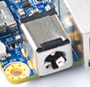
- Power Jack
- DC-12V/2A IN, 5.5*2.1mm Power Jack

- Power Key
- Plug in 12V power at power jack, then press the Power Key ( > 0.5s ) to boot NanoPC-T4.
- USB Port
- USB Type-C port has 2A overcurrent protection.
- USB 3.0 port has 2A overcurrent protection.
- Two USB 2.0 host port share 2A overcurrent protection.
- BOOT Key
- Press BOOT key to prevent the board from eMMC booting, making the board enter MASKROM mode.
- RTC
- RTC backup current is 27uA.
- Connector P/N: Molex 53398-0271
- Notes
- The Power Jack is the only power input port. All power pins at other ports are output.
- How to make T4 start automatically when power is plugged in
- For more details refer to the document: NanoPC-T4-1802-Schematic.pdf
4.2 Board Dimension

- For more details refer to the CAD document: NanoPC-T4_1802_Drawing(dxf).zip
5 Get Started
5.1 Essentials You Need
Before starting to use your NanoPC-T4 get the following items ready
- NanoPC-T4
- Type-C cable
- TF Card: Class 10 or Above, minimum 8GB SDHC
- USB to serial adapter(optinal, for debugging or access from PC host)
- A DC 12V/2A power is a must
- HDMI monitor or LCD
- USB keyboard, mouse and possible a USB hub(or a TTL to serial board)
- A host computer running Ubuntu 16.04 64 bit system or Windows 7
5.2 Debug with Serial Pins
If you want to get T4's boot messages or access T4 remotely you can operate it by using its serial pins.
- Get a USB to serial adapter and connect it to a T4:
Pin# T4's Serial Pins USB to Serial Board 1 GND GND 2 VCC5V0_SYS NC (Not Connected)
Note: if this is a FriendlyElec's Matrix USB2UART you need to turn off the "5V ON/OFF"3 UART2DBG_TX RX 4 UART2DBG_RX TX
- If you connect a USB to Serial adapter to a PC running Linux it will usually be recognized as ttyUSB0. To find out the device name, run the following commands:
 dmesg | grep ttyUSB
 ls -l /dev/ttyUSB*
- On a PC running Linux install and run minicom, and set its configuration as follows(1500000 Bps, 8N1, N)
 sudo apt-get install minicom
 minicom -s
Note: RK3399's debug serial interface's default baud rate is 1500000. Some adapter may not be able to run at this rate. You need to find a working adapter.
5.3 Flash Image to eMMC
As for a RK3399 based ARM board developed by FriendlyELEC there are three ways to flash an image to eMMC:
- Use eflasher to make a bootable SD card and flash an image to eMMC with this card
- Use a Windows' utility "AndroidTool_Release_v2.42" provided by Rockchip to flash an image to eMMC with a Type-C cable
- Use a Linux utility Linux_Upgrade_Tool_1.27 provided by Rockchip to flash an image to eMMC with a Type-C cable
If you are not familiar with the two utilities provided by Rockchip or you don't have a Type-C cable we suggest you try the first method.
5.3.1 Download Image and Utilities
Visit download link to download image files and utilities.
| Image Files | |
| rk3399-eflasher-YYYYMMDD-android.img.zip | Android 7.1.2 image file |
| rk3399-eflasher-YYYYMMDD-friendly-core-arm64.img.zip | 64-bit FriendlyCore image file(Qt 5.10.0) based on Ubuntu core 18.04 |
| rk3399-eflasher-YYYYMMDD-lubuntu.img.zip | Lubuntu Desktop |
| Flash Utility: | |
| win32diskimager.rar | Windows utility. Under Linux users can use "dd" |
5.3.2 Flash Image to eMMC with eflasher and SD card
- Get a 8G SDHC card;
- Download the "rk3399-eflasher-YYYYMMDD-XXXX.img.zip" and "win32diskimager" and extract them on a Windows PC;
- Run the "win32diskimager" utility as administrator, select your TF card, wanted file and click on "Write" to start flash the image to your TF card;
- After it is done take out the TF card and insert it to your T4's microSD slot;
- Connect a 12V/2A DC power cord and an HDMI monitor to your T4, press and hold the Power button for at least 1.5 seconds and you will see the PWR led is on and the image on SD card is booted. Around 15 seconds later the HDMI monitor will display a Window;
- Select your wanted OS with a USB mouse and click on "Next" to continue;
- After flashing is done press and release the Power button to shut down the system. After the PWR is off take out the TF card. Press and hold the Power button for at least 1.5 seconds the image will be booted from eMMC.
5.3.3 Flash Image under Windows with Type-C Cable
Visit download link to download Windows utilities and image files:
| Image Files | |
| android-nougat-images.tgz | Android 7.1.2 Image File |
| core-qte-arm64-images.tgz | FriendlyCore Image File(Qt 5.10) |
| lubuntu-desktop-images.tgz | Lubuntu Desktop with X Window |
| Flash Utility: | |
| AndroidTool_Release_v2.42.7z | Windows utility provided by Rockchip |
| DriverAssitant_v4.5.tgz | USB driver for Windows provided by Rockchip. This is needed when using AndroidTool to flash OS |
Here are the steps:
- Download DriverAssitant_v4.5.tgz, extract it and install it on a Windows PC;
- Download your wanted image from images-for-eflasher and extract it. For example the image for Android 7 is "android-nougat-images.tgz". You can ignore the "idbloader.img" and "info.conf" files.
- Download AndroidTool_Release_v2.42.7z, extract it and run AndroidTool.exe as administrator.
- Import a parameter.txt for sections and configure a file for each section if needed:

- Connect a 12V/2A DC power cord and an HDMI monitor to your T4, connect your T4 to a PC with a Type-C cable. Press and hold the Recovery button and the Power button for at least 1.5 seconds AndroidTools will prompt that a LOADER device is found
a) If eMMC hasn't been flashed with an image or the image inside is removed or damaged this eMMC will be recognized as a MASKROM device;
b) You can hold both the BOOT button and the Power button for at least 5 seconds to force the board to enter the MASKROM mode;
c) If your system shows "no device is found" you need to check if you have installed a driver or if your Type-C cable works and then try it again;
d) If your system is booted successfully you can run "reboot loader" on your board via adb or SSH and force your board to enter the LOADER mode.
- Click on "Run" to download your wanted image to eMMC. A while later after the image is flashed successfully your board will be rebooted automatically.
5.3.4 Flash Image to eMMC under Linux with Type-C Cable
Visit download link to download Windows utilities and image files
| Image Files | |
| android-nougat-images.tgz | Android 7.1.2 Image File |
| core-qte-arm64-images.tgz | FriendlyCore Image File(Qt 5.10) |
| lubuntu-desktop-images.tgz | LUbuntu Desktop with X Window |
| Flash Utility: | |
| Linux_Upgrade_Tool_1.27.rar | Linux utility provided by Rockchip |
Linux_Upgrade_Tool is a Linux utility provided by Rockchip. You need to use it together with a Type-C cable. It can be used to install an image to eMMC, delete image files from eMMC, read from and write to eMMC and etc.
- Install upgrade_tool: download Linux_Upgrade_Tool_1.27.rar, extract it and set upgrade_tool's access right
 sudo cp upgrade_tool /usr/local/sbin
 sudo chown root:root /usr/local/sbin/upgrade_tool
 sudo chmod 0755 /usr/local/sbin/upgrade_tool
- Download your wanted image from images-for-eflasher and extract it. For example the image for Lubuntu is "lubuntu-desktop-images.tgz".
- Refer to the steps in "Flash Image to eMMC with AndroidTool" to boot your board and force it to enter either LOADER or MASKROM mode;
- Run the following commands to flash Lubuntu to eMMC and reboot your board:
 sudo upgrade_tool ul MiniLoaderAll.bin
 sudo upgrade_tool di -p parameter.txt
 sudo upgrade_tool di uboot uboot.img
 sudo upgrade_tool di trust trust.img
 sudo upgrade_tool di resource resource.img
 sudo upgrade_tool di kernel kernel.img
 sudo upgrade_tool di boot boot.img
 sudo upgrade_tool di rootfs rootfs.img
 sudo upgrade_tool RD
- If you want to flash Android 7 to eMMC you can download and extract its image file and run the following commands:
 sudo upgrade_tool ul MiniLoaderAll.bin
 sudo upgrade_tool di -p parameter.txt
 sudo upgrade_tool di uboot uboot.img
 sudo upgrade_tool di trust trust.img
 sudo upgrade_tool di misc misc.img
 sudo upgrade_tool di resource resource.img
 sudo upgrade_tool di kernel kernel.img
 sudo upgrade_tool di boot boot.img
 sudo upgrade_tool di recovery recovery.img
 sudo upgrade_tool di system system.img
 sudo upgrade_tool RD
If the image's MiniLoaderAll.bin has a different version or the image you want to flash to eMMC is different from the image that already exists in eMMC you need to delete the image file in eMMC and then flash your new image to it.
Boot your board and enter the LOADER mode, run the following commands to delete the image in eMMC. If a prompt shows "Download Boot Start" and it lasts for 10 seconds you need to press the Reset button and run the following commands again.
sudo upgrade_tool EF MiniLoaderAll.binIf it succeeds you will see a prompt showing "Erase flash ok."
6 Work with Android7

FriendlyElec provides a full Android7.1 BSP for NanoPC-T4. The source code is hosted at gitlab.com and is open source. The BSP supports GPU and VPU hardware acceleration.
The NanoPC-T4 supports the FriendlyARM RC-100 remote control under Android. To get a better experience your can connect your T4 to an HDMI monitor and navigate Android.

Here is a table for the remote control's keys and corresponding functions:
Key Function Up Navigate - Up Down Navigate - Down Left Navigate - Left Right Navigate - Right OK Confirm - Volume - + Volume + Mute Mute Menu Android Menu Home Android Home Return Android Return F1 Pull-Down Android Message Bar F2 Android Screenshot F3 Switch between mouse and key
6.2 Connect MIPI Camera to T4
FriendlyElec developed a MIPI camera CAM1320 for NanoPC-T4 and it works under Android. You can use this camera to take pictures and record video. The operation is straightforward. You just need to connect the camera at your NanoPC-T4's MIPI interface, boot your T4 to Android and start Android's camera app.
The NanoPC-T4 has two MIPI interfaces: one front camera and the other rear camera:
Interface Camera Type(front or rear) MIPI-CSL1 Android rear camera MIPI-CSL2 Android front camera
6.3 Set LCD Resolution
Enter Android's Settings -> Display -> HDMI -> HDMI Resolution. The max resolution is 4K.
6.4 Rotate Display
Enter Android's Settings -> Display -> HDMI -> HDMI Rotation. It supports both landscape and portrait.
7 Work with FriendlyCore
For details about FriendlyCore refer to:FriendlyCore (based on ubuntu-core with Qt)
8 Work with Lubuntu
8.1 Introduction to Lubuntu


LUbuntu is a light-weighted Ubuntu desktop system. It is based on LXDE and has the following features:
Light-weighted - it consumes relatively less CPU resources than a common desktop system. When a system's RAM is sufficient it can achieve much better performance.
Less power consumption - it consumes relatively less power or resources than a common desktop system to achieve the same performance.
Compact & neat - its desktop is based on GTK+ 2 and supports multiple languages.
Easy to use - its GUI looks similar to MS Windows'.
Customizable - Users can customize LXDE's GUI.
Compatible - it is compatible with freedesktop.org.
The Lubuntu Desktop has been optimized for adopting Mali GPU. It has driver support for X.org and supports Hardware Cursor, OpenGL acceleration and etc.
8.2 Lubuntu Default User Account
Non-root User:
   User Name: pi
   Password: pi
Root:
   User Name: root
   Password: fa
8.3 OpenGL ES
Open a command line utility and run the following command:
glmark2-es2

8.4 Video Playing with Hardware Decoding
Open a command line utility and run the following command:
gst-player.sh
A video window will be displayed with Overlay and voices will be output to the audio interface. You can run "which gst-player.sh" to locate the script and customize video playing.
8.5 Connect USB Camera to T4
Connect a USB camera (e.g. Logitech C270) to T4, start Lubuntu, enter the "Other" menu, start "xawtv" and you will be able to preview with the camera.
8.6 5G WiFi
Click on the network icon on top right of the Lubuntu GUI, select a WiFi hotspot and proceed with prompts.
8.7 Connect NVME SSD High Speed Hard Disk to T4
Connect a NVME SSD hard disk to NanoPC-T4's M.2 interface, initialize and automatically mount the SSD by running the following commands. Before proceed turn off your T4 and connect an SSD to your T4. Power on your T4 and open a command line utility(go to top left of the GUI and enter System Tools -> LXTerminal) or SSH to your T4.
We suggest you switch to "root" by running the following command:
su -The password for "root" is "fa".
8.7.1 Detection of SSD
root@FriendlyELEC:~# cat /proc/partitions
major minor  #blocks  name
   1        0       4096 ram0
 259        0  125034840 nvme0n1
If there is a nvme0n1 device node it means an SSD is recognized by T4.
8.7.2 Partition of SSD
To mount an SSD under Linux we re-partition it as one section by running the following command:
(echo o; echo n; echo p; echo 1; echo ""; echo ""; echo w; echo q) | fdisk /dev/nvme0n1
If you want to re-partition it to multiple sections you can run "fdisk /dev/nvme0n1". For more detail about this command refer to the fdisk's manual.
8.7.3 Format Section to EXT4
After an SSD is successfully partitioned you can check its sections by running "cat /proc/partitions". The image provided treats a PCIe nvme device's sections as an eMMC's sections you will find that an SSD has some small sections.
We can check the "blocks" column and the biggest section is available for users. The /dev/nvme0n1p7 section is used to store data:
root@FriendlyELEC:~# cat /proc/partitions
major minor  #blocks  name
   1        0       4096 ram0
 259        0  125034840 nvme0n1
 259        1       4096 nvme0n1p1
 259        2       4096 nvme0n1p2
 259        3       4096 nvme0n1p3
 259        4      12288 nvme0n1p4
 259        5      32768 nvme0n1p5
 259        6      32768 nvme0n1p6
 259        7  124932440 nvme0n1p7
The following command formats a section to ext4:
mkfs.ext4 /dev/nvme0n1p7
8.7.4 Auto Mount SSD on System Startup
Before we mount an SSD's section you need to know its Block ID. You can check it by running "blkid":
blkid /dev/nvme0n1p7
/dev/nvme0n1p7: UUID="13fb682e-ef40-4c71-b98b-3d17403e1205" TYPE=“ext4"
Add a "Block ID" to "/etc/fstab" and here is what it looks like
UUID=<Block ID> /media/nvme ext4 defaults 0 0
You need to replace <Block ID> with the UUID obtained by running "blkid". To mount the SSD in our example we made the "/etc/fstab" file as follows:
UUID=13fb682e-ef40-4c71-b98b-3d17403e1205 /media/nvme ext4 defaults 0 0
We want to mount an SSD to "/media/nvme" but this directory doesn't exist. Therefore we create it and change its access right by running the following commands:
mkdir /media/nvme
chmod 777 /media/nvme
Run "mount" to check if the SSD is mounted successfully:
mount /media/nvme
You can reboot your T4 to check if your SSD will be automatically mounted:
poweroff
Reboot your T4, if you can see the following screen your SSD is mounted successfully:

8.7.5 SSD Read & Write
You can test SSD read and write speed. In our test we used a LITEON T10 120GB SSD. Different SSDs may have different results.
Write to SSD:
# dd if=/dev/zero of=/media/nvme/deleteme.dat bs=32M count=128
128+0 records in
128+0 records out
4294967296 bytes (4.3 GB, 4.0 GiB) copied, 12.5671 s, 342 MB/s
Read from SSD:
# dd if=/media/nvme/deleteme.dat of=/dev/zero bs=32M count=128
128+0 records in
128+0 records out
4294967296 bytes (4.3 GB, 4.0 GiB) copied, 6.72943 s, 638 MB/s
9 Make Your Own OS Image
9.1 Setup Development Environment
If you want to compile an Android image we suggest you use a PC running a 64-bit Ubuntu 16.04.
sudo apt-get install bison g++-multilib git gperf libxml2-utils make python-networkx zip
sudo apt-get install flex curl libncurses5-dev libssl-dev zlib1g-dev gawk minicom
sudo apt-get install openjdk-8-jdk
For more details refer to https://source.android.com/source/initializing.html 。
9.2 Install Cross Compiler
9.2.1 Install aarch64-linux-gcc 6.4
Download and extract compiler:
git clone https://github.com/friendlyarm/prebuilts.git
sudo mkdir -p /opt/FriendlyARM/toolchain
sudo tar xf prebuilts/gcc-x64/aarch64-cortexa53-linux-gnu-6.4.tar.xz -C /opt/FriendlyARM/toolchain/
Add the compiler's path to the PATH variable by appending the following lines to the "~/.bashrc" file:
export PATH=/opt/FriendlyARM/toolchain/6.4-aarch64/bin:$PATH
export GCC_COLORS=auto
Run the "~/.bashrc" script to make the compiler setting effective in the current shell. Note:there is a space after ".":
. ~/.bashrcThis is a 64-bit compiler and cannot be run on a 32-bit Linux. After installation is done you can verify it by running the following commands:
aarch64-linux-gcc -v
Using built-in specs.
COLLECT_GCC=aarch64-linux-gcc
COLLECT_LTO_WRAPPER=/opt/FriendlyARM/toolchain/6.4-aarch64/libexec/gcc/aarch64-cortexa53-linux-gnu/6.4.0/lto-wrapper
Target: aarch64-cortexa53-linux-gnu
Configured with: /work/toolchain/build/aarch64-cortexa53-linux-gnu/build/src/gcc/configure --build=x86_64-build_pc-linux-gnu
--host=x86_64-build_pc-linux-gnu --target=aarch64-cortexa53-linux-gnu --prefix=/opt/FriendlyARM/toolchain/6.4-aarch64
--with-sysroot=/opt/FriendlyARM/toolchain/6.4-aarch64/aarch64-cortexa53-linux-gnu/sysroot --enable-languages=c,c++
--enable-fix-cortex-a53-835769 --enable-fix-cortex-a53-843419 --with-cpu=cortex-a53
...
Thread model: posix
gcc version 6.4.0 (ctng-1.23.0-150g-FA)
9.3 Compile Android7 Source Code
9.3.1 Download Android7 Source Code
All the NanoPC-T4's source code is hosted at gitlab, you can download it by running the following commands:
git clone https://gitlab.com/friendlyelec/rk3399-nougat.git
9.3.2 Compile & Make Image File
Compile Android7 by running the following commands:
cd rk3399-nougat
./build-nanopc-t4.sh -F -M
9.3.3 Update Image File
After compilation is done an image file will be generated under Android7's "rockdev/Image-nanopc_t4/" directory. Update the image file on T4 by running the following commands:
1) Insert a bootable SD card with EFLASHER to a card adapter and insert this adapter to a host PC and the SD card's sections will be automatically mounted;
2) Copy all the files under "rockdev/Image-nanopc_t4/" to the "nougat" directory of this SD card's FRIENDLYARM section;
3) Insert this SD card to your NanoPC-T4 and reinstall Android;
9.4 Compile Lubuntu Kernel
9.4.1 compile Linux kernel
git clone https://github.com/friendlyarm/kernel-rockchip --depth 1 -b nanopi4-linux-v4.4.y
cd kernel-rockchip
make ARCH=arm64 nanopi4_linux_defconfig
make ARCH=arm64 rk3399-nanopi4-rev00.img
9.4.2 Update Lubuntu Kernel
To update the kernel you need to use the Linux_Upgrade_Tool_1.27.rar utility. Refer to the aforementioned sections on how to use this utility.
9.5 Access Serial Interface
For now only UART4 is available for users:
Serial Interface Serial Device UART0 Used by Bluetooth UART1 Used by Gbps Ethernet UART2 Used by Serial Debug Port UART3 Used by Gbps Ethernet UART4 Available, device name is /dev/ttyS4 (note: this is only applicable for ROM released after 20180618)
10 More OS Support
10.1 DietPi_NanoPCT4-ARMv8-Stretch
DietPi is a light-weighted system. Its image file can be as small as 345M bytes. It takes much less resources. It has a DietPi-RAMlog utility. These features allow users to exploit its huge potentials.
FriendlyElec doesn't provide technical support for DietPi.
Here are some steps to boot a DietPi:
- Download DriverAssitant_v4.5.tgz, extract it and install it on a Windows PC;
- Download DietPi_NanoPCT4-ARMv8-Stretch DietPi_NanoPCT4-ARMv8-Stretch, extract it, enter "Image_and_Tools" and run "AndroidTool.exe" as administrator
- It is assumed that the section configuration(parameter.txt) is imported and here is a table:

- Connect a 12V/2A DC power cord and an HDMI monitor to your T4, connect your T4 to a PC with a Type-C cable. Press and hold the Recovery button and the Power button for at least 1.5 seconds AndroidTools will prompt that a LOADER device is found
a)If eMMC hasn't been flashed with an image or the image inside is removed or damaged this eMMC will be recognized as a MASKROM device;
b)You can hold both the BOOT button and the Power button for at least 5 seconds to force the board to enter the MASKROM mode;
c)If your system shows "no device is found" you need to check if you have installed a driver or if your Type-C cable works and then try it again;
d)If your system is booted successfully you can run "reboot loader" on your board via adb or SSH and force your board to enter the LOADER mode.
- Click on "Run" to download your wanted image to eMMC. A while later after the image is flashed successfully your board will be rebooted automatically.

Login User Name:root
Password:dietpi
10.2 WiFi
By default WiFi is not enabled. You can enable WiFi by running "dietpi-config". dietpi-config
   --> Network Options:Adapters
       --> WiFi  Change Wireless Network Settings
           --> Scan  Scan and Connect
Select a WiFi hotspot, type its password and connect

11 Link to Rockchip Resources
Link to Rockchip's resources: https://gitlab.com/friendlyelec/rk3399-nougat/tree/nanopc-t4-nougat/RKDocs
12 Update Log
12.1 June-19-2018
- Released English version
12.2 July-5-2018
- Updated section 5.3
- Added sections 7, 9.2 and 10