Difference between revisions of "Matrix - IR Receiver"
(→Basic Device Operation) |
(→Basic Device Operation) |
||
| Line 26: | Line 26: | ||
==Basic Device Operation== | ==Basic Device Operation== | ||
| − | + | *The IR receiver contains a photo diode, amplifier, band pass filter, integrator, hysteresis comparator and etc. When the IR receiver detects infrared signals it sends them to the preamplifier and band pass filter. After the signals are processed by the band pass filter (30KHz ~ 60KHz) they will be further processed by the integrator and comparator and finally be output as High or Low. | |
| − | *The IR receiver contains a photo diode, amplifier, band pass filter, integrator, hysteresis comparator and etc. When the IR receiver detects infrared signals it sends them to the | + | *Note: the output signal is the reversal of the input signal. |
| − | * | + | |
==Download Matrix Source Code== | ==Download Matrix Source Code== | ||
Revision as of 10:41, 29 December 2015
Contents
1 Introduction
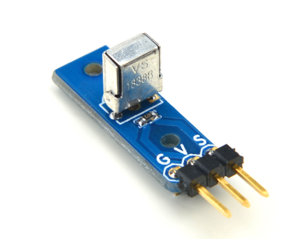
- The Matrix-IR receiver is a 38KHz infrared receiver that receives 38KHz signals from an infrared remote control, amplifies and filers them to other devices. Its signal decoding is implemented by programming MCU.
- Transmission distance: 12 ~ 13 meters.
2 Features
- GPIO control, 3.3/5V
- Small
- 2.54mm spacing pin header
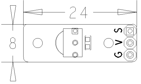
- PCB Dimension(mm): 8 x 24
- Pin Description:
| Pin | Description |
| S | GPIO |
| V | Supply Voltage 5V |
| G | Ground |
3 Basic Device Operation
- The IR receiver contains a photo diode, amplifier, band pass filter, integrator, hysteresis comparator and etc. When the IR receiver detects infrared signals it sends them to the preamplifier and band pass filter. After the signals are processed by the band pass filter (30KHz ~ 60KHz) they will be further processed by the integrator and comparator and finally be output as High or Low.
- Note: the output signal is the reversal of the input signal.
4 Download Matrix Source Code
All the matrix modules' code samples are open source. They are maintained on GitHub: https://github.com/friendlyarm/matrix.git
Each branch in this hub contains the matrix modules' code samples for a board that the matrix modules can work with.
- The matrix-nanopi branch contains the matrix modules' code samples for the NanoPi
- The matrix-nanopi2 branch contains the matrix modules' code samples for the NanoPi 2
- The matrix-tiny4412 branch contains the matrix modules' code samples for the Tiny4412;
- The matrix-raspberrypi branch contains the matrix modules' code samples for the RaspberryPi;
Please follow the steps below to get the source code:
Install the git utility on a PC running Ubuntu14.04
$ sudo apt-get install git
Clone the matrix code from GitHub
$ git clone https://github.com/friendlyarm/matrix.git
If this is successful a "matrix" directory will be generated, which will contain all the matrix modules' code samples.
5 Connect to NanoPi 2
5.1 Hardware Connection
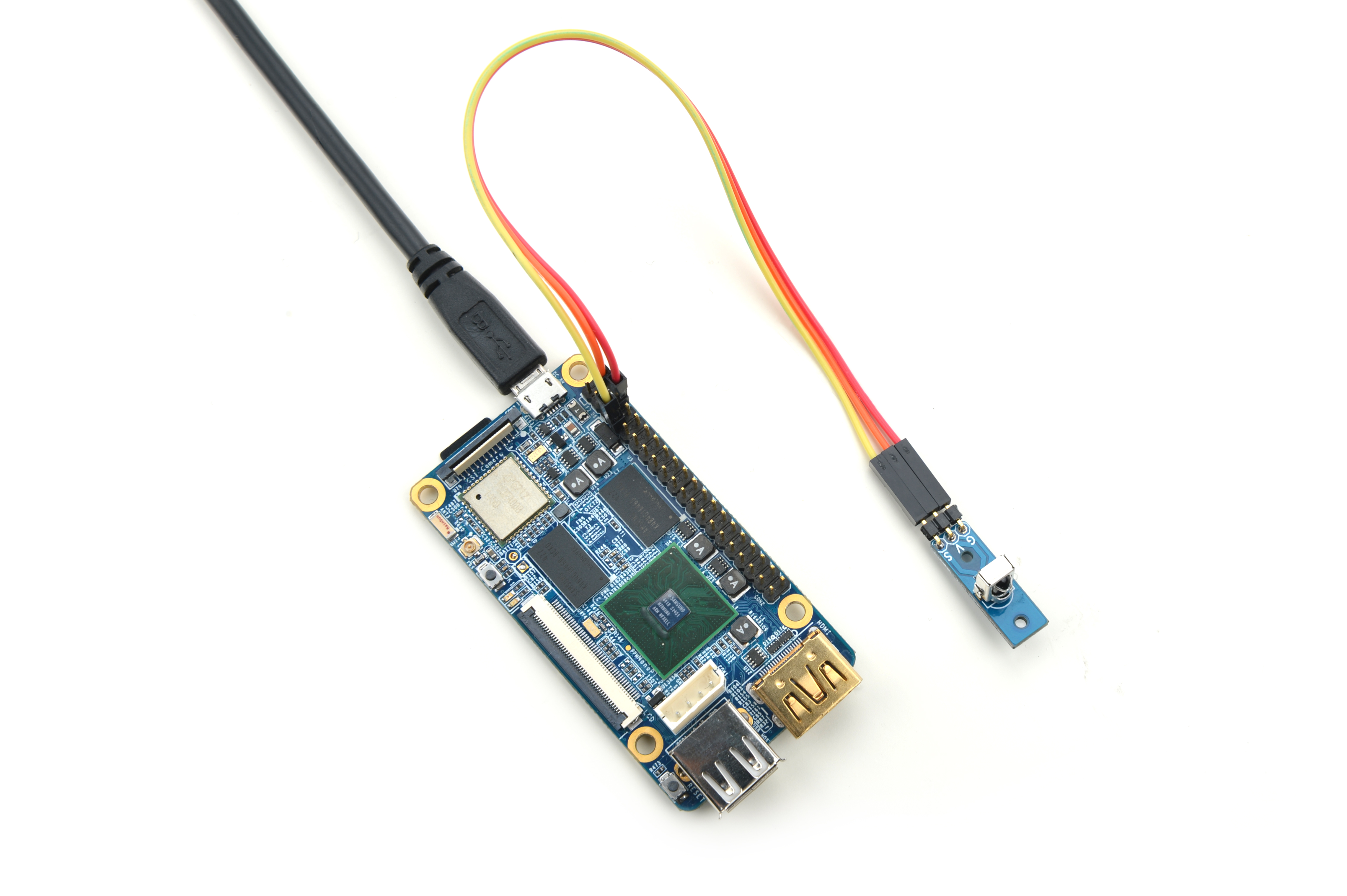
Please refer to the following connection diagram to connect the Matrix-IR_Receiver to the NanoPi 2:

Connection Details:
| Matrix-IR_Receiver | NanoPi 2 |
| S | Pin7 |
| V | Pin4 |
| G | Pin6 |
5.2 Compile Test Program
Please login the matrix hub and enter the nanopi2 branch
$ cd matrix
$ git checkout nanopi2
Compile the Matrix code
$ make CROSS_COMPILE=arm-linux- clean
$ make CROSS_COMPILE=arm-linux-
$ make CROSS_COMPILE=arm-linux- install
Note: please make sure to install the cross compiler "arm-linux-gcc-4.9.3" on your PC, which is used to compile files for the NanoPi 2.
Generated library files are under the "install/lib" directory. The test program is under the "install/usr/bin" directory. The modules are under the "modules" directory.
5.3 Run Test Program
Please insert a TF card which is flashed with Debian to a Linux host and mount its boot and rootfs sections.
We assume the rootfs is mounted to /media/rootfs then please run the following commands to copy the module, library and test program to the card
$ cp modules /media/rootfs/ -r
$ cp install/lib/* /media/rootfs/lib/ -d
$ cp install/usr/bin/* /media/rootfs/usr/bin/
Insert this TF card to your NanoPi 2, power on and run the following commands to load the driver
$ cd /modules
$ insmod matrix_ir_recv.ko
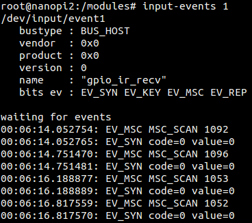
If the driver is successfully loaded a device node will be generated under /dev/input/. In our test case the node was event1.
There is an open source utility "input-utils" which can be used to read the event device's data. Here is how it works:
$ apt-get install input-utils
$ input-events 1
1 stands for device node "event1"
You can use a regular remote control to send signals to it. Here is what you expect to observe:


