Difference between revisions of "Matrix - IR Counter"
(→介绍) |
(→Basic Device Operation) |
||
| (7 intermediate revisions by the same user not shown) | |||
| Line 1: | Line 1: | ||
[[Matrix - IR Counter/zh|查看中文]] | [[Matrix - IR Counter/zh|查看中文]] | ||
| − | |||
==Introduction== | ==Introduction== | ||
[[File:Matrix-IR_Counter.png|thumb|]] | [[File:Matrix-IR_Counter.png|thumb|]] | ||
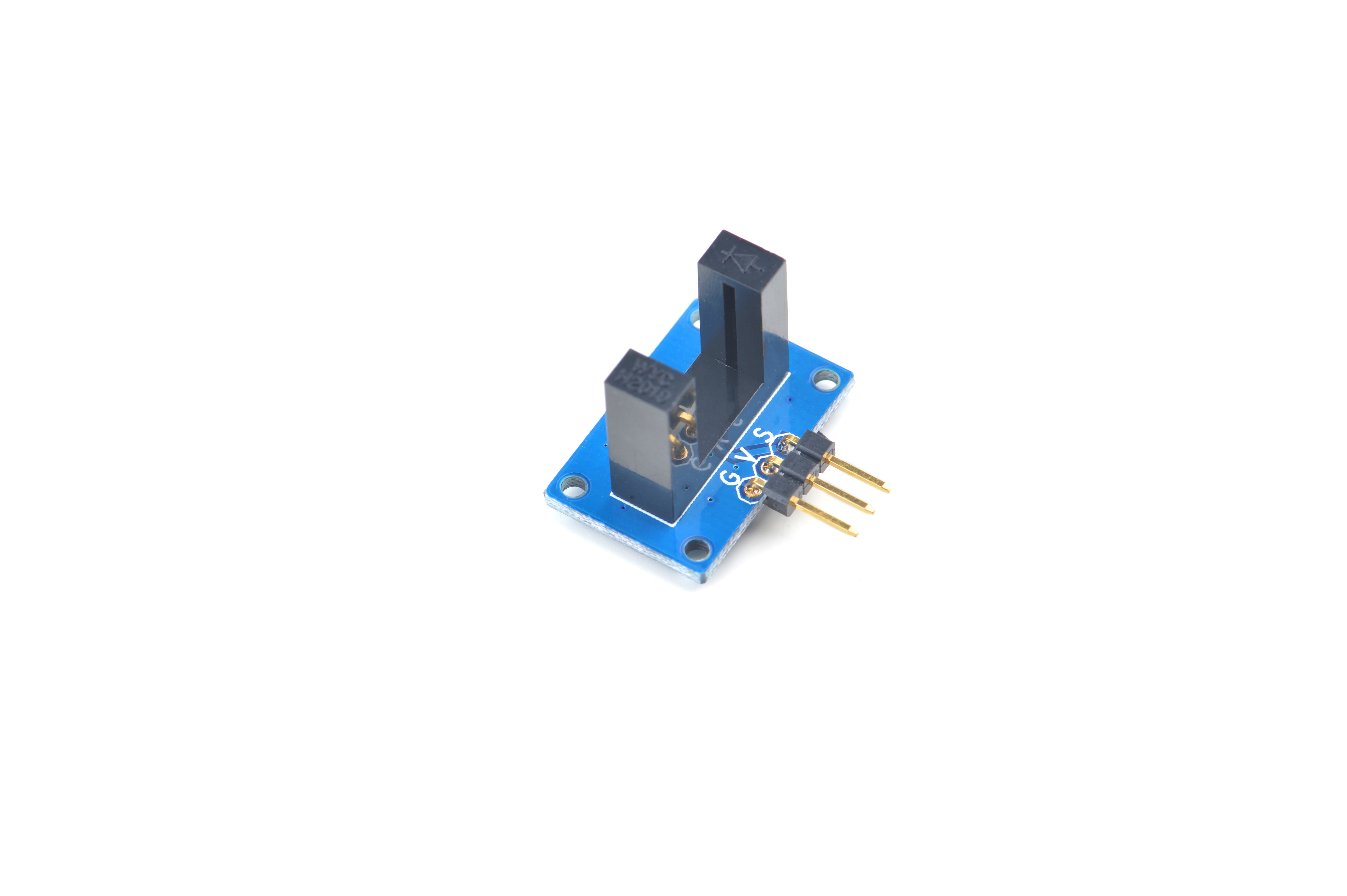
| − | * | + | * The Matrix IR_Counter uses a U type infrared beam photoelectric sensor. It has a 5 pin 2.54 mm pitch pin-header. Pin V is power supply and Pin G is ground. When there is no presence of an object Pin S outputs high |
| − | == | + | ==Features== |
| − | * | + | * GPIO interface |
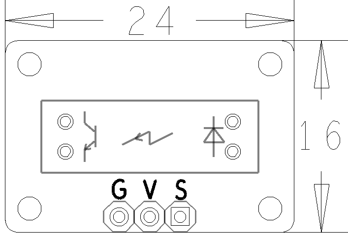
| − | * | + | * PCB dimension(mm): 16 x 24 mm |
| − | + | ||
[[File:Matrix-IR_Counter_PCB.png|frameless|400px|]] | [[File:Matrix-IR_Counter_PCB.png|frameless|400px|]] | ||
| − | * | + | * Pin Description: |
{| class="wikitable" | {| class="wikitable" | ||
|- | |- | ||
| − | | | + | |Pin || Description |
|- | |- | ||
| − | |S || | + | |S || Digital Output |
|- | |- | ||
| − | |V || | + | |V || Supply Voltage 5V |
|- | |- | ||
| − | |G || | + | |G || Ground |
|} | |} | ||
| − | == | + | ==Basic Device Operation== |
| − | * | + | * There are a transmitter and a receiver on the two wings of the U type slot separately. When the transmitter emits infrared signals an optic axis will be generated. If an object passes through the U type slot and blocks the optic axis the photoelectric switch will generate signals. When the optic axis is not blocked the receiver will receive infrared signals and the module will output high otherwise the module will output low. |
| − | == | + | ==Applications== |
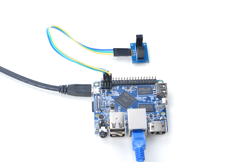
| − | === | + | ===Connect to NanoPi M1=== |
| − | + | Refer to the following connection diagram to connect the module to the NanoPi M1:<br> | |
[[File:Matrix-IR_Counter_nanopi_m1.jpg|frameless|600px|Matrix-IR_Counter_nanopi_m1]] | [[File:Matrix-IR_Counter_nanopi_m1.jpg|frameless|600px|Matrix-IR_Counter_nanopi_m1]] | ||
| − | + | Connection Details: | |
{| class="wikitable" | {| class="wikitable" | ||
|- | |- | ||
| Line 44: | Line 42: | ||
|} | |} | ||
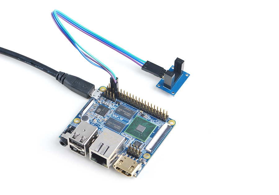
| − | === | + | ===Connect to NanoPi 2=== |
| − | + | Refer to the following connection diagram to connect the module to the NanoPi 2:<br> | |
[[File:Matrix-IR_Counter_nanopi_2.jpg|frameless|600px|Matrix-IR_Counter_nanopi_2]] | [[File:Matrix-IR_Counter_nanopi_2.jpg|frameless|600px|Matrix-IR_Counter_nanopi_2]] | ||
| − | + | Connection Details: | |
{| class="wikitable" | {| class="wikitable" | ||
|- | |- | ||
| Line 60: | Line 58: | ||
|} | |} | ||
| − | === | + | ===Connect to NanoPi M2 / NanoPi 2 Fire=== |
| − | NanoPi | + | Refer to the following connection diagram to connect the module to the NanoPi M2/ NanoPi 2 Fire.<br> |
| − | + | ||
[[File:Matrix-IR_Counter_nanopi_m2.jpg|frameless|600px|Matrix-IR_Counter_nanopi_m2]] | [[File:Matrix-IR_Counter_nanopi_m2.jpg|frameless|600px|Matrix-IR_Counter_nanopi_m2]] | ||
| − | + | Connection Details: | |
{| class="wikitable" | {| class="wikitable" | ||
|- | |- | ||
| Line 77: | Line 74: | ||
|} | |} | ||
| − | === | + | ===Connect to NanoPC-T2=== |
| − | + | Refer to the following connection diagram to connect the module to the NanoPC-T2:<br> | |
[[File:Matrix-IR_Counter_NanoPC-T2.jpg|frameless|600px|Matrix-IR_Counter_NanoPC-T2]] | [[File:Matrix-IR_Counter_NanoPC-T2.jpg|frameless|600px|Matrix-IR_Counter_NanoPC-T2]] | ||
| − | + | Connection Details: | |
{| class="wikitable" | {| class="wikitable" | ||
|- | |- | ||
| Line 93: | Line 90: | ||
|} | |} | ||
| − | == | + | ==Compile & Run Test Program== |
| − | + | Boot your ARM board with Debian and copy the matrix code: | |
<syntaxhighlight lang="bash"> | <syntaxhighlight lang="bash"> | ||
$ apt-get update && apt-get install git | $ apt-get update && apt-get install git | ||
$ git clone https://github.com/friendlyarm/matrix.git | $ git clone https://github.com/friendlyarm/matrix.git | ||
</syntaxhighlight> | </syntaxhighlight> | ||
| − | + | If your cloning is done successfully a "matrix" directory will be generated. | |
| − | + | Compile and install Matrix: | |
<syntaxhighlight lang="bash"> | <syntaxhighlight lang="bash"> | ||
$ cd matrix | $ cd matrix | ||
| Line 107: | Line 104: | ||
</syntaxhighlight> | </syntaxhighlight> | ||
| − | + | Run test program: | |
<syntaxhighlight lang="bash"> | <syntaxhighlight lang="bash"> | ||
$ matrix-gpio_int | $ matrix-gpio_int | ||
</syntaxhighlight> | </syntaxhighlight> | ||
| − | + | Note: this module is not plug and play therefore before running the module please make sure it is connected to an ARM board.<br> | |
| − | + | Here is what you should observe:<br> | |
<syntaxhighlight lang="bash"> | <syntaxhighlight lang="bash"> | ||
Waiting event... | Waiting event... | ||
Device[0] value is 1 | Device[0] value is 1 | ||
</syntaxhighlight> | </syntaxhighlight> | ||
| − | + | If there is presence of an object in front of it an event will be triggered. | |
| − | == | + | ==Code Sample== |
| − | + | This Matrix code sample can work with all the ARM boards mentioned in this module's wiki. The name of this code sample is "matrix-gpio_int". Here is its source code: | |
<syntaxhighlight lang="c"> | <syntaxhighlight lang="c"> | ||
int main(int argc, char ** argv) | int main(int argc, char ** argv) | ||
| Line 160: | Line 157: | ||
} | } | ||
</syntaxhighlight> | </syntaxhighlight> | ||
| − | + | For more details about this APIs called in this code sample refer to [[Matrix API reference manual]] <br> | |
| + | |||
| + | ==Resources== | ||
| − | == | + | ==Update Log== |
| + | ===June-21-2016=== | ||
| + | * Created English wiki | ||
Latest revision as of 04:15, 21 June 2016
Contents
1 Introduction
- The Matrix IR_Counter uses a U type infrared beam photoelectric sensor. It has a 5 pin 2.54 mm pitch pin-header. Pin V is power supply and Pin G is ground. When there is no presence of an object Pin S outputs high
2 Features
- GPIO interface
- PCB dimension(mm): 16 x 24 mm
- Pin Description:
| Pin | Description |
| S | Digital Output |
| V | Supply Voltage 5V |
| G | Ground |
3 Basic Device Operation
- There are a transmitter and a receiver on the two wings of the U type slot separately. When the transmitter emits infrared signals an optic axis will be generated. If an object passes through the U type slot and blocks the optic axis the photoelectric switch will generate signals. When the optic axis is not blocked the receiver will receive infrared signals and the module will output high otherwise the module will output low.
4 Applications
4.1 Connect to NanoPi M1
Refer to the following connection diagram to connect the module to the NanoPi M1:

Connection Details:
| Matrix-IR_Counter | NanoPi M1 |
| S | Pin7 |
| V | Pin4 |
| G | Pin6 |
4.2 Connect to NanoPi 2
Refer to the following connection diagram to connect the module to the NanoPi 2:
Matrix-IR_Counter_nanopi_2
Connection Details:
| Matrix-IR_Counter | NanoPi 2 |
| S | Pin7 |
| V | Pin4 |
| G | Pin6 |
4.3 Connect to NanoPi M2 / NanoPi 2 Fire
Refer to the following connection diagram to connect the module to the NanoPi M2/ NanoPi 2 Fire.

Connection Details:
| Matrix-IR_Counter | NanoPi M2 |
| S | Pin7 |
| V | Pin4 |
| G | Pin6 |
4.4 Connect to NanoPC-T2
Refer to the following connection diagram to connect the module to the NanoPC-T2:
Matrix-IR_Counter_NanoPC-T2
Connection Details:
| Matrix-IR_Counter | NanoPC-T2 |
| S | Pin15 |
| V | Pin29 |
| G | Pin30 |
5 Compile & Run Test Program
Boot your ARM board with Debian and copy the matrix code:
$ apt-get update && apt-get install git
$ git clone https://github.com/friendlyarm/matrix.git
If your cloning is done successfully a "matrix" directory will be generated.
Compile and install Matrix:
$ cd matrix
$ make && make install
Run test program:
$ matrix-gpio_intNote: this module is not plug and play therefore before running the module please make sure it is connected to an ARM board.
Here is what you should observe:
Waiting event...
Device[0] value is 1
If there is presence of an object in front of it an event will be triggered.
6 Code Sample
This Matrix code sample can work with all the ARM boards mentioned in this module's wiki. The name of this code sample is "matrix-gpio_int". Here is its source code:
int main(int argc, char ** argv)
{
    int i, board;
    int retSize = -1;
    char value[ARRAY_SIZE(dev)];

    if ((board = boardInit()) < 0) {
        printf("Fail to init board\n");
        return -1;
    }

    if (argc == 2)
        dev[0].pin = atoi(argv[1]);
    system("modprobe "DRIVER_MODULE);
    signal(SIGINT, intHandler);
    if (board == BOARD_NANOPI_T2)
        dev[0].pin = GPIO_PIN(15);
    printf("Use GPIO_PIN(%d)\n", dev[0].pin);
    if ((devFD =sensorInit(dev, ARRAY_SIZE(dev))) == -1) {
        printf("Fail to init sensor\n");
        goto err;
    }
    printf("Waiting event...\n");
    if ((retSize = sensorRead(devFD, value, ARRAY_SIZE(dev))) == -1) {
        printf("Fail to read sensors\n");
    }
    if (retSize > 0) {
        i = 0;
        for (i=0; i<retSize; i++) {
            printf("Device[%d] value is %d\n", i, value[i]);
        }
    }
    sensorDeinit(devFD);
err:
    system("rmmod "DRIVER_MODULE);
    return 0;
}
For more details about this APIs called in this code sample refer to Matrix API reference manual
7 Resources
8 Update Log
8.1 June-21-2016
- Created English wiki

