Difference between revisions of "Matrix - I2C LCD1602"
From FriendlyELEC WiKi
(→LCD1602) |
(→LCD1602) |
||
| Line 27: | Line 27: | ||
===LCD1602=== | ===LCD1602=== | ||
*The PCF8574 module's P0 - P7's pin spec are as follows: | *The PCF8574 module's P0 - P7's pin spec are as follows: | ||
| − | |||
[[File:1602.png|frameless|400px|1602]] | [[File:1602.png|frameless|400px|1602]] | ||
| − | *RS is command/data, RW is read/write, E is Enable(), BL is backlight and D4-D7 are data bits. | + | *RS is command/data, RW is read/write, E is Enable(Edge-triggering), BL is backlight and D4-D7 are data bits. |
| − | * | + | *An LCD uses four data bits. However the RS has eight bits. Therefore for each write to RS you need to write DB7-DB4 first and then DB3-DB0. |
| − | + | *Note:the LCD has 192 commonly used characters stored in CGROM. For example if you want to display "A" you can directly write "A". In addition the LCD module allows users to define eight user-defined characters which are stored in CGRAM. The details about CGRAM are not be covered here. | |
| − | * | + | |
==How To== | ==How To== | ||
Revision as of 08:38, 17 August 2015
Contents
1 Introduction
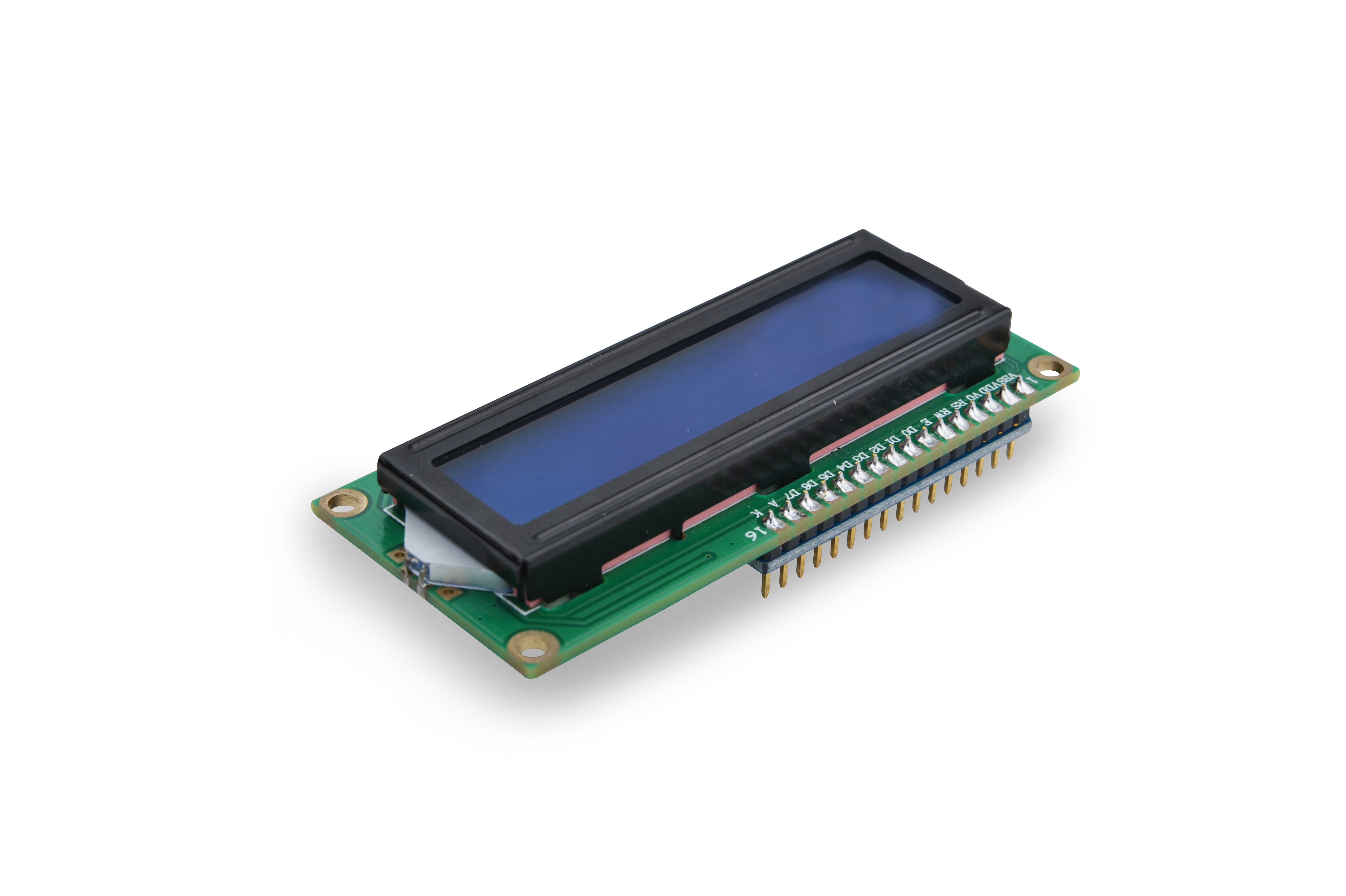
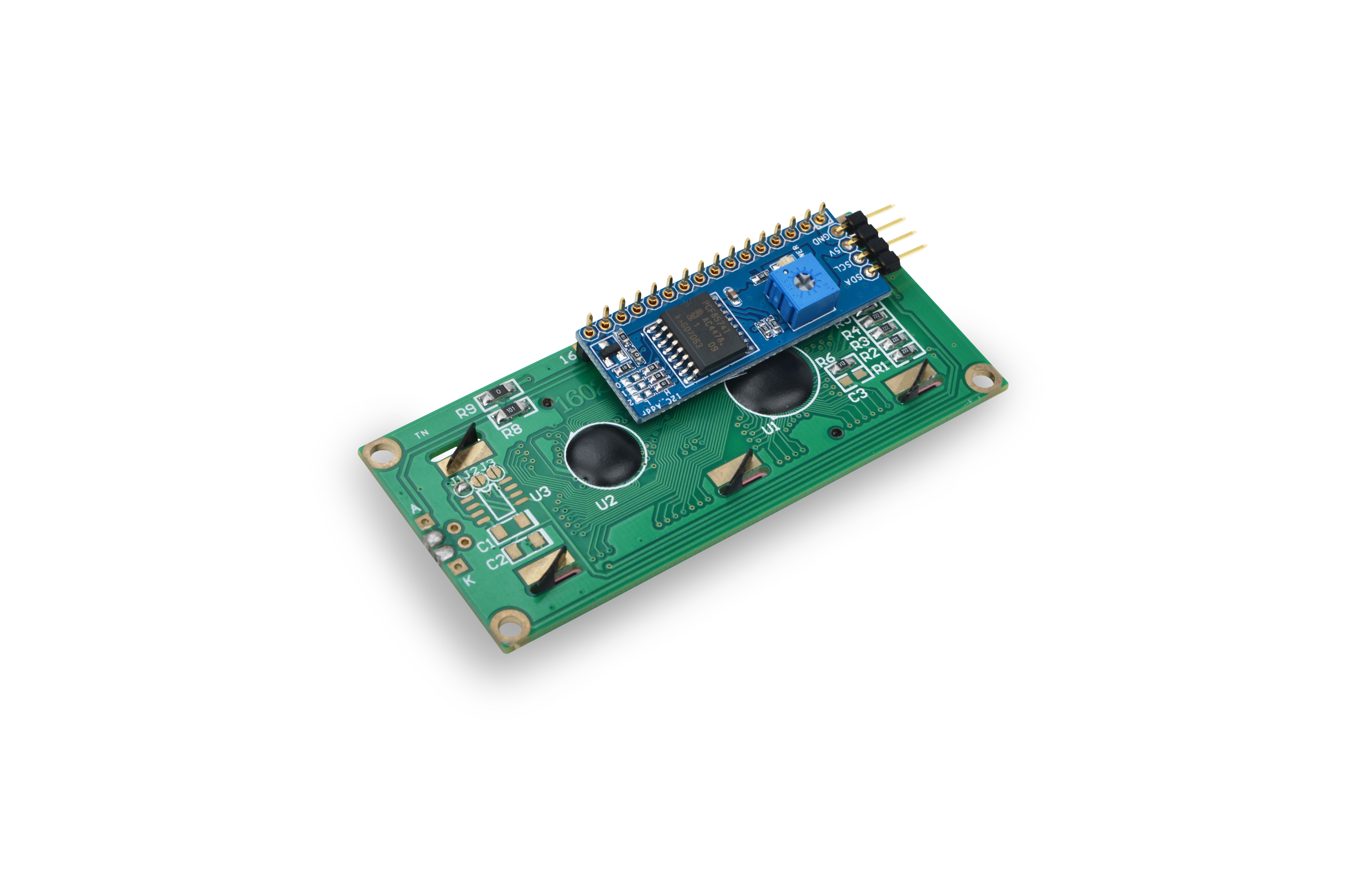
This is an LCD module which has an I2C controller. It can display 16 x 2 characters. Its interface is parallel. To simplify its application we designed a controller on this module, which interfaces with other modules through I2C and transfers received signals to parallel signals to LCD1602. It can display, turn on and off back light.
2 Features
- I2C interface. It can display characters, and turn on and off back light
- 2.54 mm spacing pin
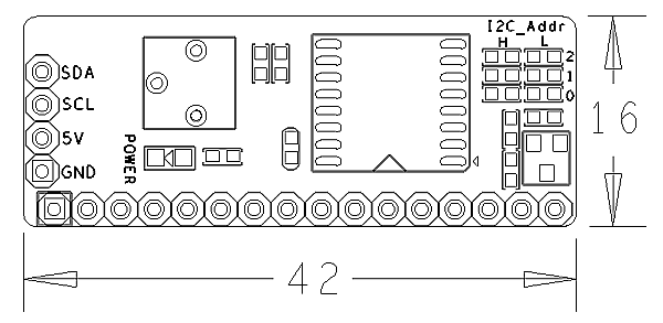
- I2C PCB dimension:16 x 42 mm
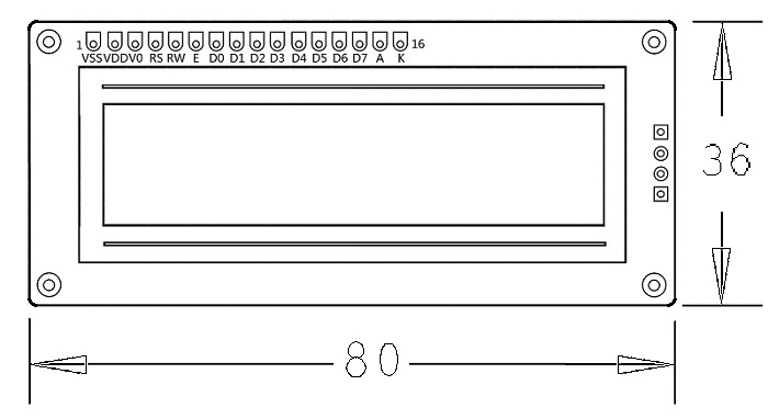
- LCD1602 PCB dimension: 36 x 80 mm
3 How They Work
3.1 PCF8574
- The PCF8574 module's interface is I2C parallel which is 8 bit and has 8 IO (P0 - P7) outputs.
- The PCF8574 module uses the PCF8574T chip whose address diagram is as follows:
- If you set A2-A0 all to "1" the address will be 0x27(0100111). By default RW is "0" and the module is in the "write" mode.
- If it is in the write mode and the address is set you can open "i2c-0" and write data to it.
- If you want to set it to "read" (RW set to "1") please refer to PCF8574's datasheet for more details
3.2 LCD1602
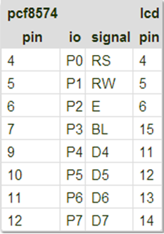
- The PCF8574 module's P0 - P7's pin spec are as follows:
- RS is command/data, RW is read/write, E is Enable(Edge-triggering), BL is backlight and D4-D7 are data bits.
- An LCD uses four data bits. However the RS has eight bits. Therefore for each write to RS you need to write DB7-DB4 first and then DB3-DB0.
- Note:the LCD has 192 commonly used characters stored in CGROM. For example if you want to display "A" you can directly write "A". In addition the LCD module allows users to define eight user-defined characters which are stored in CGRAM. The details about CGRAM are not be covered here.
4 How To
4.1 Connection
- Connect to Tiny4412 SDK (1506)
- GND: Ground
- VCC: 5V
- SDA: I2C SDA
- SCL: I2C SCL
4.2 Code Sample in C Under Linux
#include <stdio.h>
#include <unistd.h>
#include <sys/types.h>
#include <sys/stat.h>
#include <fcntl.h>
#include <stdlib.h>
#include "libfahw.h"

void test(char* line1, char* line2)
{
    int devFD;
    if ((devFD = LCD1602Init()) == -1) {
        printf("Fail to init LCD1602\n");
        return;
    }

            if (LCD1602Clear(devFD) == -1) {
                    printf("Fail to Clear\n");
                    return;
            }

    if (LCD1602DispLines(devFD, line1, line2) == -1) {
        printf("Fail to Display String\n");
        return ;
    }

    LCD1602DeInit(devFD);
}

int main(int argc, char ** argv) {
    int i;
    for (i=0; i<10; i++) {
         test("FriendlyARM", "From 2003");
         sleep(3);
    }
    return 0;
}
4.3 Compile and Run
git clone http://github.com/friendlyarm/fa-hardware.git
cd fa-hardware
cd demo
cd matrix-i2c_lcd1602
make
Copy your compiled bin to your board and you are ready to go.
