Difference between revisions of "Matrix - Compact Kit B"
(→Applications) |
|||
| (29 intermediate revisions by 2 users not shown) | |||
| Line 1: | Line 1: | ||
[[Matrix - Compact Kit B/zh|查看中文]] | [[Matrix - Compact Kit B/zh|查看中文]] | ||
| + | |||
| + | ==Introduction== | ||
| + | [[File:Matrix-Compact_Kit_B.png|thumb|]] | ||
| + | * The Matrix Compact Kit B is a FriendlyARM developed compact board with various hardware resources, interfaces and ports. It contains user keys, LEDs, buzzer, ADC, compass, temperature sensor, IR receiver and TFT interface. It works with FriendlyARM's NanoPi 2 Fire and NanoPi M2 via its 40 pin male connector and is compatible with Raspberry Pi and Arduino boards. In addition you can connect various devices to its IO pin-header. | ||
| + | |||
| + | ==Features== | ||
| + | Matrix - Compact Kit B contains the following components:<br> | ||
| + | * 0.9 TFT LCD | ||
| + | |||
| + | * 3 x Switch | ||
| + | |||
| + | * 4 x 5mm LED | ||
| + | |||
| + | * Buzzer | ||
| + | |||
| + | * ADC | ||
| + | |||
| + | * Potentiometer | ||
| + | |||
| + | * 40pin Female Connector | ||
| + | |||
| + | * 4pin pin-header – I2C | ||
| + | |||
| + | * 4pin pin-header – UART | ||
| + | |||
| + | * 3pin double pin-header – 3.3V and GND | ||
| + | |||
| + | * 18B20 Temperature Sensor | ||
| + | |||
| + | * IR Receiver | ||
| + | |||
| + | * 10 x 3pin pin-header – 3 x AIO & 7 x DIO (two can be configured to PWM and four can be configured to SPI) | ||
| + | |||
| + | * Compass | ||
| + | |||
| + | ==Dimensional Diagram and Pin Description== | ||
| + | * PCB Dimension(mm):64 x 40 | ||
| + | [[File:Matrix-Compact_Kit_B_PCB.png|frameless|400px|]] | ||
| + | * '''40 pin female connector's pin description''' | ||
| + | ::{| class="wikitable" | ||
| + | |- | ||
| + | |Pin# || Name ||Pin# || Name | ||
| + | |- | ||
| + | |1 || SYS_3.3V ||2 || VDD_5V | ||
| + | |- | ||
| + | |3 || I2C0_SDA ||4 || VDD_5V | ||
| + | |- | ||
| + | |5 || I2C0_SCL ||6 || DGND | ||
| + | |- | ||
| + | |7 || GPIOD8/PPM ||8 || UART3_TXD/GPIOD21 | ||
| + | |- | ||
| + | |9 || DGND ||10 || UART3_RXD/GPIOD17 | ||
| + | |- | ||
| + | |11 || UART4_TX/GPIOB29 ||12 || GPIOD1/PWM0 | ||
| + | |- | ||
| + | |13 || GPIOB30 ||14 || DGND | ||
| + | |- | ||
| + | |15 || GPIOB31 ||16 || GPIOC14/PWM2 | ||
| + | |- | ||
| + | |17 || SYS_3.3V ||18 || GPIOB27 | ||
| + | |- | ||
| + | |19 || SPI0_MOSI/GPIOC31 ||20 || DGND | ||
| + | |- | ||
| + | |21 || SPI0_MISO/GPIOD0 ||22 || UART4_RX/GPIOB28 | ||
| + | |- | ||
| + | |23 || SPI0_CLK/GPIOC29 ||24 || SPI0_CS/GPIOC30 | ||
| + | |- | ||
| + | |25 || DGND ||26 || GPIOB26 | ||
| + | |- | ||
| + | |27 || I2C1_SDA ||28 || I2C1_SCL | ||
| + | |- | ||
| + | |29 || GPIOC8 ||30 || DGND | ||
| + | |- | ||
| + | |31 || GPIOC7 ||32 || GPIOC28 | ||
| + | |- | ||
| + | |33 || GPIOC13/PWM1 ||34 || DGND | ||
| + | |- | ||
| + | |35 || SPI2_MISO/GPIOC11 ||36 || SPI2_CS/GPIOC10 | ||
| + | |- | ||
| + | |37 || AliveGPIO3 ||38 || SPI2_MOSI/GPIOC12 | ||
| + | |- | ||
| + | |39 || DGND ||40 || SPI2_CLK/GPIOC9 | ||
| + | |} | ||
| + | * '''30 pin header's pin description''' | ||
| + | ::{| class="wikitable" | ||
| + | |- | ||
| + | |Pin# || Name ||Pin# || Name ||Pin# || Name | ||
| + | |- | ||
| + | |1 || GND ||2 || VDD_5V ||3 ||A1_PCF | ||
| + | |- | ||
| + | |4 || GND ||5 || VDD_5V ||6 ||A2_PCF | ||
| + | |- | ||
| + | |7 || GND ||8 || VDD_5V ||9 ||A3_PCF | ||
| + | |- | ||
| + | |10 || GND ||11 || VDD_5V ||12 ||D1_Pi11 | ||
| + | |- | ||
| + | |13 || GND ||14 || VDD_5V ||15 ||D2_Pi33 | ||
| + | |- | ||
| + | |16 || GND ||17 || VDD_5V ||18 ||D3_Pi16 | ||
| + | |- | ||
| + | |19 || GND ||20 || VDD_5V ||21 ||D4_Pi19 | ||
| + | |- | ||
| + | |22 || GND ||23 || VDD_5V ||24 ||D5_Pi21 | ||
| + | |- | ||
| + | |25 || GND ||26 || VDD_5V ||27 ||D6_Pi23 | ||
| + | |- | ||
| + | |28 || GND ||29 || VDD_5V ||30 ||D7_Pi24 | ||
| + | |- | ||
| + | |} | ||
| + | |||
| + | [[File:18B20 and IRR.png |thumb|300px|18B20 and IR Receiver's Layout]] | ||
| + | * '''DS18B20 and IR receiver's pin description''' | ||
| + | ::{| class="wikitable" | ||
| + | |- | ||
| + | |Module ||Pin# || Name ||Pin# || Name ||Pin# || Name | ||
| + | |- | ||
| + | |18B20 ||1 || VDD_5V ||2 || DATA ||3 || GND | ||
| + | |- | ||
| + | |IR Receiver ||1 || DATA ||2 || GND ||3 || VDD_5V | ||
| + | |- | ||
| + | |} | ||
| + | |||
| + | |||
| + | ==Applications== | ||
| + | ===Connect to NanoPi M1=== | ||
| + | Refer to the following connection diagram to connect the module to the NanoPi M1:<br> | ||
| + | [[File:Matrix-Compact_Kit_B_nanopi_m1.jpg|frameless|600px|Matrix-Compact_Kit_B_nanopi_m1]] | ||
| + | |||
| + | ===Connect to NanoPi M2 / NanoPi 2 Fire=== | ||
| + | Refer to the following connection diagram to connect the module to the NanoPi M2/ NanoPi 2 Fire:<br> | ||
| + | [[File:Matrix-Compact_Kit_B_nanopi_m2.jpg|frameless|600px|Matrix-Compact_Kit_B_nanopi_m2]] | ||
| + | |||
| + | ==Compile & Run Test Program== | ||
| + | Boot your ARM board with Debian and copy the matrix code: | ||
| + | <syntaxhighlight lang="bash"> | ||
| + | $ apt-get update && apt-get install git | ||
| + | $ git clone https://github.com/friendlyarm/matrix.git | ||
| + | </syntaxhighlight> | ||
| + | If your cloning is done successfully a "matrix" directory will be generated. | ||
| + | |||
| + | Compile and install Matrix: | ||
| + | <syntaxhighlight lang="bash"> | ||
| + | $ cd matrix | ||
| + | $ make && make install | ||
| + | </syntaxhighlight> | ||
| + | |||
| + | Run test program: | ||
| + | <syntaxhighlight lang="bash"> | ||
| + | $ matrix-compact_kit | ||
| + | </syntaxhighlight> | ||
| + | Note: this module is not plug and play therefore before running the module please make sure it is connected to an ARM board.<br> | ||
| + | Here is what you should observe:<br> | ||
| + | <syntaxhighlight lang="bash"> | ||
| + | LED blinking 1 | ||
| + | LED blinking 2 | ||
| + | Button: 1 1 1 | ||
| + | The channel0 value is 2070 | ||
| + | The angle is 336.3 | ||
| + | Pwm start | ||
| + | Pwm stop | ||
| + | </syntaxhighlight> | ||
| + | |||
| + | Run Qt program to test the TFT LCD: | ||
| + | <syntaxhighlight lang="bash"> | ||
| + | cd matrix/demo/nanopi-status | ||
| + | ./build.sh | ||
| + | ./run.sh /dev/fb-st7735s | ||
| + | </syntaxhighlight> | ||
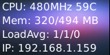
| + | The program will present the system's basic information. Here is what you expect to observe:<br> | ||
| + | [[File:st7735s-status.pnc|frameless|600px|st7735s-status]] | ||
| + | |||
| + | ==Code Sample== | ||
| + | This Matrix code sample can work with all the ARM boards mentioned in this module's wiki. The name of this code sample is "matrix-compact_kit". Here is its source code: | ||
| + | <syntaxhighlight lang="c"> | ||
| + | int main(int argc, char ** argv) | ||
| + | { | ||
| + | int board; | ||
| + | |||
| + | if ((board = boardInit()) < 0) { | ||
| + | printf("Fail to init board\n"); | ||
| + | return -1; | ||
| + | } | ||
| + | testLED(board); | ||
| + | readButton(); | ||
| + | readADC(); | ||
| + | readCompass(); | ||
| + | testPWM(board); | ||
| + | // readTemp(); | ||
| + | // testIR(); | ||
| + | |||
| + | return 0; | ||
| + | } | ||
| + | </syntaxhighlight> | ||
| + | For more details about this APIs called in this code sample refer to [[Matrix API reference manual]] <br> | ||
| + | |||
| + | <!--- | ||
| + | ==Download Matrix Source Code== | ||
| + | All the matrix modules' code samples are open source. They are maintained on GitHub: https://github.com/friendlyarm/matrix.git <br> | ||
| + | Each branch in this hub contains the matrix modules' code samples for a board that the matrix modules can work with.<br> | ||
| + | * The matrix-nanopi branch contains the matrix modules' code samples for the NanoPi; | ||
| + | * The matrix-nanopi2 branch contains the matrix modules' code samples for the NanoPi 2; | ||
| + | * The matrix-tiny4412 branch contains the matrix modules' code samples for the Tiny4412; | ||
| + | * The matrix-raspberrypi branch contains the matrix modules' code samples for the RaspberryPi; | ||
| + | |||
| + | Follow the steps below to get the source code<br> | ||
| + | Install the git utility on a PC running Ubuntu14.04 | ||
| + | <syntaxhighlight lang="bash"> | ||
| + | $ sudo apt-get install git | ||
| + | </syntaxhighlight> | ||
| + | |||
| + | Clone the matrix code from GitHub | ||
| + | <syntaxhighlight lang="bash"> | ||
| + | $ git clone https://github.com/friendlyarm/matrix.git | ||
| + | </syntaxhighlight> | ||
| + | If this is successful a "matrix" directory will be generated, which will contain all the matrix modules' code samples. | ||
| + | |||
| + | ==Connect to NanoPi 2 Fire== | ||
| + | ===Hardware Connection=== | ||
| + | Refer to the following connection diagram to connect the Matrix-Compact_Kit_B to the NanoPi 2 Fire<br> | ||
| + | [[File:Matrix-Compact_Kit_B_nanopi2.jpg|frameless|600px|Matrix-Compact_Kit_B_nanopi2]] | ||
| + | |||
| + | ===Compile Test Program=== | ||
| + | Login to the matrix hub and enter the nanopi2 branch | ||
| + | <syntaxhighlight lang="bash"> | ||
| + | $ cd matrix | ||
| + | $ git checkout nanopi2 | ||
| + | </syntaxhighlight> | ||
| + | |||
| + | Compile the Matrix code | ||
| + | <syntaxhighlight lang="bash"> | ||
| + | $ make CROSS_COMPILE=arm-linux- clean | ||
| + | $ make CROSS_COMPILE=arm-linux- | ||
| + | $ make CROSS_COMPILE=arm-linux- install | ||
| + | </syntaxhighlight> | ||
| + | Note: make sure to install the cross compiler "arm-linux-gcc-4.9.3" on your PC, which is used to compile files for the NanoPi 2.<br> | ||
| + | Generated library files are under the "install/lib" directory. The test program is under the "install/usr/bin" directory.<br> | ||
| + | The modules are under the "modules" directory. The driver's source code is in github: https://github.com/friendlyarm/linux-3.4.y.git <br> | ||
| + | |||
| + | ===Copy Test Program=== | ||
| + | Insert a TF card which is flashed with Debian into a Linux host and mount its boot and rootfs sections.<br> | ||
| + | We assume the rootfs is mounted to /media/rootfs then run the following commands to copy the module, library and test program to the card.<br> | ||
| + | <syntaxhighlight lang="bash"> | ||
| + | $ cp modules /media/rootfs/ -r | ||
| + | $ cp install/lib/* /media/rootfs/lib/ -d | ||
| + | $ cp install/usr/bin/* /media/rootfs/usr/bin/ | ||
| + | </syntaxhighlight> | ||
| + | |||
| + | ===Test LCD=== | ||
| + | Insert this TF card to your NanoPi 2 Fire, power on and run the following commands.<br> | ||
| + | <syntaxhighlight lang="bash"> | ||
| + | $ cd /modules | ||
| + | $ insmod fbtft_device.ko name=matrix-st7735s gpios=dc:58,reset:63,cs:59 | ||
| + | $ sudo FRAMEBUFFER=/dev/fb-st7735s startx & | ||
| + | </syntaxhighlight> | ||
| + | "fbtft_device" is the LCD's driver.After it is loaded the LCD will be initialized.<br> | ||
| + | "startx" sets the LCD to the output device. Here is what you should expect:<br> | ||
| + | [[File:03.jpg|frameless|600px|03]] | ||
| + | |||
| + | ===Test Buzzer=== | ||
| + | Jump the buzzer to "ON" and run the following commands:<br> | ||
| + | <syntaxhighlight lang="bash"> | ||
| + | $ cd /modules | ||
| + | $ insmod matrix_pwm.ko | ||
| + | $ matrix-buzzer | ||
| + | </syntaxhighlight> | ||
| + | Here is what you expect to observe:<br> | ||
| + | [[File:matrix-buzzer_result.png|frameless|600px|matrix-buzzer_result]] <br> | ||
| + | You will hear the buzzer beeping and the PWM's default frequency is 1KHz and the duty cycle is 50%. | ||
| + | |||
| + | ===Access LED=== | ||
| + | {| class="wikitable" | ||
| + | |- | ||
| + | |LED || CPU GPIO || Linux ID(used in the Linux Kernel) || ID on the Compact Kit B board | ||
| + | |- | ||
| + | |Red LED1 || GPIOB28 || 60 || 28 | ||
| + | |- | ||
| + | |Green LED2 || GPIOC7 || 71 || 31 | ||
| + | |- | ||
| + | |Blue LED3 || ALIVEGPIO3 || 163 || 37 | ||
| + | |- | ||
| + | |Yellow LED4 || GPIOC11 || 75 || 35 | ||
| + | |} | ||
| + | Take LED1 as an example, run the following commands: | ||
| + | <syntaxhighlight lang="bash"> | ||
| + | $ cd /sys/class/gpio/ | ||
| + | $ echo 60 > export | ||
| + | $ echo out > gpio60/direction | ||
| + | $ echo 1 > gpio60/value | ||
| + | </syntaxhighlight> | ||
| + | "1" turns on LED1 and "0" turns off LED1. | ||
| + | |||
| + | ===Read User Key Value=== | ||
| + | {| class="wikitable" | ||
| + | |- | ||
| + | |User Key || CPU GPIO || Linux ID(used in the Linux Kernel) || ID on the Compact Kit B board | ||
| + | |- | ||
| + | |KEY1 || GPIOC10 || 74 || 36 | ||
| + | |- | ||
| + | |KEY2 || GPIOC12 || 76 || 38 | ||
| + | |- | ||
| + | |KEY3 || GPIOC9 || 73 || 40 | ||
| + | |} | ||
| + | Take KEY1 as an example run the following commands: | ||
| + | <syntaxhighlight lang="bash"> | ||
| + | $ cd /sys/class/gpio/ | ||
| + | $ echo 74 > export | ||
| + | $ echo in > gpio74/direction | ||
| + | $ cat gpio74/value | ||
| + | </syntaxhighlight> | ||
| + | When KEY1 is pressed "value" is 0 otherwise "value" is 1. | ||
| + | |||
| + | ===Test AD=== | ||
| + | Run the following command to get Channel 0's value: | ||
| + | <syntaxhighlight lang="bash"> | ||
| + | $ cd /modules | ||
| + | $ insmod pcf8591.ko | ||
| + | $ matrix-adc | ||
| + | </syntaxhighlight> | ||
| + | When you turn the resistor the AD value will change. Here is what you should expect:<br> | ||
| + | [[File:matrix-cpt_kit_result2.png|frameless|600px|matrix-cpt_kit_result_ad]] | ||
| + | |||
| + | ===Test Compass=== | ||
| + | Run the following command to activate the compass: | ||
| + | <syntaxhighlight lang="bash"> | ||
| + | $ matrix-compass | ||
| + | </syntaxhighlight> | ||
| + | When you change the module's direction you will get a changing value. Here is what you should expect:<br> | ||
| + | [[File:matrix-cpt_kit_result3.png|frameless|600px|matrix-cpt_kit_result_cps]] | ||
| + | |||
| + | ===Test Temperature Sensor=== | ||
| + | |||
| + | Run the following commands to test the temperature sensor: | ||
| + | <syntaxhighlight lang="bash"> | ||
| + | $ cd /modules | ||
| + | $ insmod w1-gpio.ko | ||
| + | $ insmod w1-gpio-board.ko gpio=72 | ||
| + | $ matrix-temp_sensor | ||
| + | </syntaxhighlight> | ||
| + | gpio=72 means pin GPIOC8 is used. 72 is the index number used in the Linux kernel.<br> | ||
| + | Here is what you should expect:<br> | ||
| + | [[File:matrix-temperature_sensor_result.png|frameless|600px|matrix-temperature_sensor_result]] | ||
| + | |||
| + | ===Test IR Receiver=== | ||
| + | |||
| + | Run the following commands to test the IR receiver: | ||
| + | <syntaxhighlight lang="bash"> | ||
| + | $ cd /modules | ||
| + | $ insmod matrix_ir_recv.ko gpio=92 | ||
| + | </syntaxhighlight> | ||
| + | gpio=92 means pin GPIOC28 is used. 92 is the index number used in the Linux kernel.<br> | ||
| + | After the driver is successfully loaded a device node will be generated under /dev/input/. We assume it is event1 in our example.<br> | ||
| + | |||
| + | An open source utility "input-utils" can be used to read a device's data. Here is how to do it:<br> | ||
| + | <syntaxhighlight lang="bash"> | ||
| + | $ apt-get install input-utils | ||
| + | $ input-events 1 | ||
| + | </syntaxhighlight> | ||
| + | "1" stands for device node event1.<br> | ||
| + | |||
| + | If you send data to the IR receiver with a remote control you will be able to see this:<br> | ||
| + | [[File:matrix-ir_receiver_result.png|frameless|600px|matrix-ir_receiver_result]] | ||
| + | |||
| + | ===Code Samples in Python=== | ||
| + | |||
| + | ==Connect to NanoPi== | ||
| + | |||
| + | ==Connect to Tiny4412== | ||
| + | |||
| + | ==Connect to Raspberry Pi== | ||
| + | |||
| + | ==Connect to Arduino== | ||
| + | ---> | ||
| + | ==Resources== | ||
| + | *[Schematic]([http://wiki.friendlyarm.com/wiki/images/9/90/SCHEMATIC1_martix_compact_B.pdf Matrix - Compact Kit B-Schematic.pdf]) | ||
| + | *[0.9'LCD datasheet]([http://wiki.friendlyarm.com/wiki/images/3/3b/0.9inch_TFT_ST7735S.pdf Matrix - Compact Kit B-0.9'LCD datasheet.pdf]) | ||
| + | |||
| + | ==Update Log== | ||
| + | ===May-23-2016=== | ||
| + | * Released English version | ||
| + | ===June-19-2016=== | ||
| + | * Re-organized and simplified wiki | ||
Latest revision as of 10:33, 19 June 2016
Contents
1 Introduction

- The Matrix Compact Kit B is a FriendlyARM developed compact board with various hardware resources, interfaces and ports. It contains user keys, LEDs, buzzer, ADC, compass, temperature sensor, IR receiver and TFT interface. It works with FriendlyARM's NanoPi 2 Fire and NanoPi M2 via its 40 pin male connector and is compatible with Raspberry Pi and Arduino boards. In addition you can connect various devices to its IO pin-header.
2 Features
Matrix - Compact Kit B contains the following components:
- 0.9 TFT LCD
- 3 x Switch
- 4 x 5mm LED
- Buzzer
- ADC
- Potentiometer
- 40pin Female Connector
- 4pin pin-header – I2C
- 4pin pin-header – UART
- 3pin double pin-header – 3.3V and GND
- 18B20 Temperature Sensor
- IR Receiver
- 10 x 3pin pin-header – 3 x AIO & 7 x DIO (two can be configured to PWM and four can be configured to SPI)
- Compass
3 Dimensional Diagram and Pin Description
- PCB Dimension(mm):64 x 40

- 40 pin female connector's pin description
Pin# Name Pin# Name 1 SYS_3.3V 2 VDD_5V 3 I2C0_SDA 4 VDD_5V 5 I2C0_SCL 6 DGND 7 GPIOD8/PPM 8 UART3_TXD/GPIOD21 9 DGND 10 UART3_RXD/GPIOD17 11 UART4_TX/GPIOB29 12 GPIOD1/PWM0 13 GPIOB30 14 DGND 15 GPIOB31 16 GPIOC14/PWM2 17 SYS_3.3V 18 GPIOB27 19 SPI0_MOSI/GPIOC31 20 DGND 21 SPI0_MISO/GPIOD0 22 UART4_RX/GPIOB28 23 SPI0_CLK/GPIOC29 24 SPI0_CS/GPIOC30 25 DGND 26 GPIOB26 27 I2C1_SDA 28 I2C1_SCL 29 GPIOC8 30 DGND 31 GPIOC7 32 GPIOC28 33 GPIOC13/PWM1 34 DGND 35 SPI2_MISO/GPIOC11 36 SPI2_CS/GPIOC10 37 AliveGPIO3 38 SPI2_MOSI/GPIOC12 39 DGND 40 SPI2_CLK/GPIOC9
- 30 pin header's pin description
Pin# Name Pin# Name Pin# Name 1 GND 2 VDD_5V 3 A1_PCF 4 GND 5 VDD_5V 6 A2_PCF 7 GND 8 VDD_5V 9 A3_PCF 10 GND 11 VDD_5V 12 D1_Pi11 13 GND 14 VDD_5V 15 D2_Pi33 16 GND 17 VDD_5V 18 D3_Pi16 19 GND 20 VDD_5V 21 D4_Pi19 22 GND 23 VDD_5V 24 D5_Pi21 25 GND 26 VDD_5V 27 D6_Pi23 28 GND 29 VDD_5V 30 D7_Pi24

- DS18B20 and IR receiver's pin description
Module Pin# Name Pin# Name Pin# Name 18B20 1 VDD_5V 2 DATA 3 GND IR Receiver 1 DATA 2 GND 3 VDD_5V
4 Applications
4.1 Connect to NanoPi M1
Refer to the following connection diagram to connect the module to the NanoPi M1:

4.2 Connect to NanoPi M2 / NanoPi 2 Fire
Refer to the following connection diagram to connect the module to the NanoPi M2/ NanoPi 2 Fire:

5 Compile & Run Test Program
Boot your ARM board with Debian and copy the matrix code:
$ apt-get update && apt-get install git
$ git clone https://github.com/friendlyarm/matrix.git
If your cloning is done successfully a "matrix" directory will be generated.
Compile and install Matrix:
$ cd matrix
$ make && make install
Run test program:
$ matrix-compact_kitNote: this module is not plug and play therefore before running the module please make sure it is connected to an ARM board.
Here is what you should observe:
LED blinking 1
LED blinking 2
Button:  1 1 1
The channel0 value is 2070
The angle is 336.3
Pwm start
Pwm stop
Run Qt program to test the TFT LCD:
cd matrix/demo/nanopi-status
./build.sh
./run.sh /dev/fb-st7735s
The program will present the system's basic information. Here is what you expect to observe:
6 Code Sample
This Matrix code sample can work with all the ARM boards mentioned in this module's wiki. The name of this code sample is "matrix-compact_kit". Here is its source code:
int main(int argc, char ** argv)
{
    int board;

    if ((board = boardInit()) < 0) {
        printf("Fail to init board\n");
        return -1;
    }
    testLED(board);
    readButton();
    readADC();
    readCompass();
    testPWM(board);
    // readTemp();
    // testIR();

    return 0;
}
For more details about this APIs called in this code sample refer to Matrix API reference manual
7 Resources
- [Schematic](Matrix - Compact Kit B-Schematic.pdf)
- [0.9'LCD datasheet](Matrix - Compact Kit B-0.9'LCD datasheet.pdf)
8 Update Log
8.1 May-23-2016
- Released English version
8.2 June-19-2016
- Re-organized and simplified wiki