Difference between revisions of "Matrix - Analog to Digital Converter"
(→特性) |
(→工作原理) |
||
| Line 44: | Line 44: | ||
|} | |} | ||
| − | == | + | ==Basic Device Operation== |
| − | + | The PCF8591's I2C-bus is for bidirectional, two-line communication between different ICs or modules. The two lines are a Serial DAta line (SDA) and a Serial CLock line (SCL). Both lines must | |
| − | <br> | + | be connected to a positive supply via a pull-up resistor. Data transfer may be initiated only when the bus is not busy. The AINT0 - AINT4 pins are analog inputs which can be programmed to single-ended or differential inputs. The supply voltage is 0 - VDD.<br> |
| + | |||
1、PCF8591在I2C总线系统通过激活来发送一个有效的地址到设备中,可编程地址必须根据地址引脚A0、A1、A2来设置。I2C协议中信息发送开始后发送的第一个字节是地址信息,地址字节的最后一位是用于设置以后数据传输方向的读/写位。 | 1、PCF8591在I2C总线系统通过激活来发送一个有效的地址到设备中,可编程地址必须根据地址引脚A0、A1、A2来设置。I2C协议中信息发送开始后发送的第一个字节是地址信息,地址字节的最后一位是用于设置以后数据传输方向的读/写位。 | ||
<br> | <br> | ||
Revision as of 07:25, 23 September 2015
Contents
1 Introduction
- The Matrix-Analog_to_Digital_Converter is a single-chip, single-supply low-power 8-bit CMOS data acquisition device.
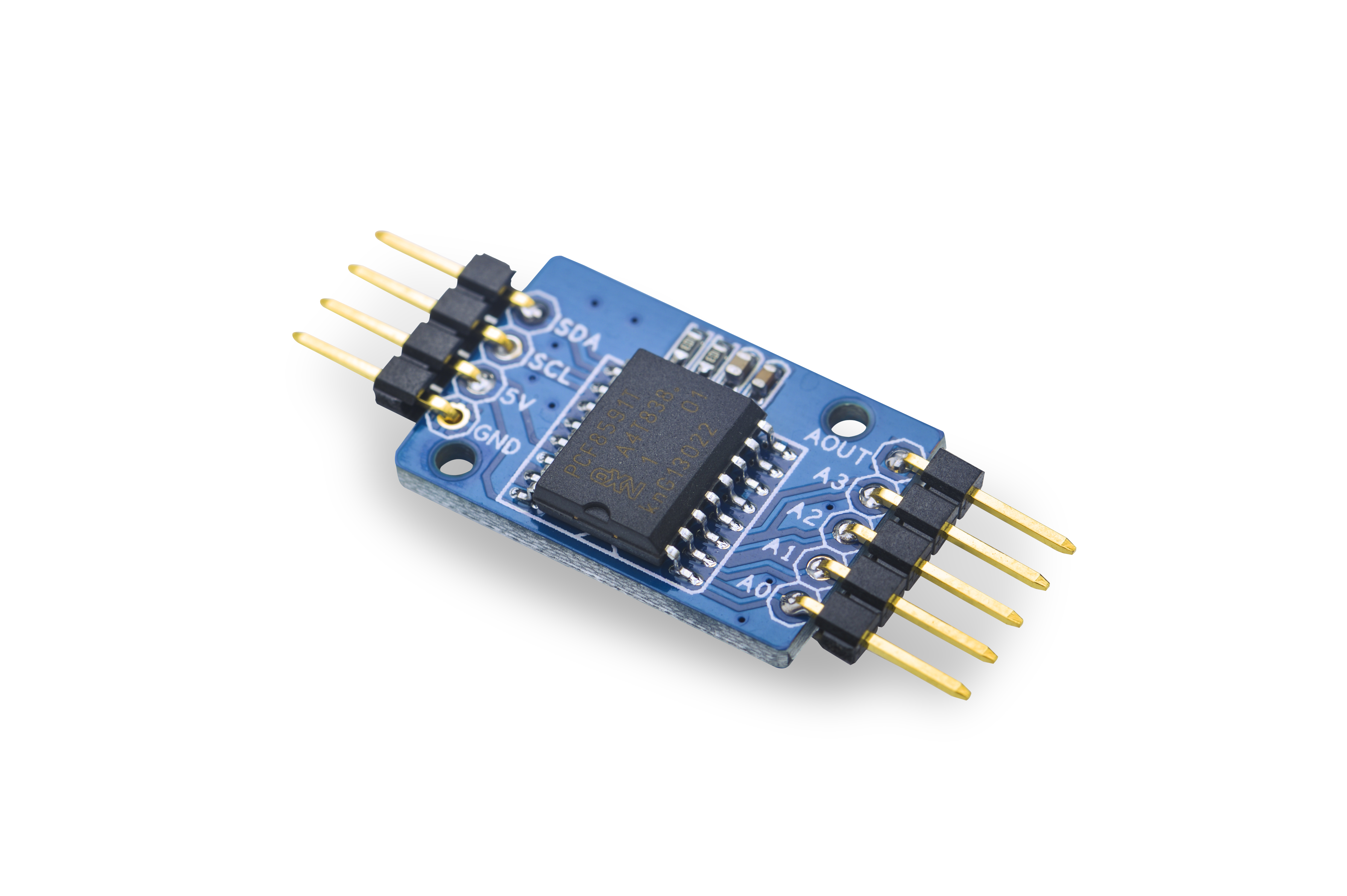
- It utilizes the PCF8591 chip with four analog inputs, one analog output and a serial I2C-bus interface. Three address pins A0, A1 and A2 are used for programming the hardware address, allowing
the use of up to eight devices connected to the I2C-bus without additional hardware. Address, control and data to and from the device are transferred serially via the two-line bidirectional I2C-bus. The maximum conversion rate is given by the maximum speed of the I2C-bus.
- The I2C hardware address is configured to 1001000x
- The operating supply voltage is from 2.5V to 6.0V,Among the 2.54 mm spacing pin header the 5V pin is the supply voltage. If you need 0 - 3.3V analog signals and keep the acquisition resolution you can connect it to a 3.3V supply voltage.
2 Features
- Wide range supply voltage: 2.5V - 6.0V
- I2C interface: 3.3V/5V
- 8-bit A/D x 4
- 8-bit D/A x 1
- Small and easy to be used in various situations
- 2.54 mm spacing pin
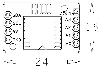
- PCB dimension (mm): 16 x 24
- Pin Description:
| Pin | Description |
| SDA | I2C SDA |
| SCL | I2C SCL |
| 5V | Supply Voltage 5V |
| GND | Ground |
| AOUT | Analog Output |
| A3 | Analog Input3 |
| A2 | Analog Input2 |
| A1 | Analog Input1 |
| A0 | Analog Input0 |
3 Basic Device Operation
The PCF8591's I2C-bus is for bidirectional, two-line communication between different ICs or modules. The two lines are a Serial DAta line (SDA) and a Serial CLock line (SCL). Both lines must
be connected to a positive supply via a pull-up resistor. Data transfer may be initiated only when the bus is not busy. The AINT0 - AINT4 pins are analog inputs which can be programmed to single-ended or differential inputs. The supply voltage is 0 - VDD.
1、PCF8591在I2C总线系统通过激活来发送一个有效的地址到设备中,可编程地址必须根据地址引脚A0、A1、A2来设置。I2C协议中信息发送开始后发送的第一个字节是地址信息,地址字节的最后一位是用于设置以后数据传输方向的读/写位。
2、发送到PCF8591 的第二个字节将被存储在控制寄存器,用于控制器件功能。控制寄存器的高半字节用于允许模拟输出,和将模拟输入编程为单端或差分输入。低半字节选择一个由高半字节定义的模拟输入通道。
3、在A/D 转换周期将临时使用片上D/A 转换器和高增益比较器。一个A/D 转换周期总是开始于发送一个有效读模式地址给PCF8591 之后。A/D 转换周期在应答时钟脉冲的后沿被触发,并在传输前一次转换结果时执行A/D转换器采用。
4 下载Matrix源码
Matrix配件相关的代码是完全开源的,统一由一个仓库进行管理:git://github.com/friendlyarm/matrix.git
该仓库里不同的分支代表着Matrix配件所支持的不同开发板。
- nanopi分支包含了Matrix对NanoPi的支持;
- tiny4412分支包含了Matrix对Tiny4412的支持;
- raspberrypi分支包含了Matrix对RaspberryPi的支持;
在主机PC上安装git,以Ubuntu14.04为例
$ sudo apt-get install git
克隆Matrix配件代码仓库
$ git clone git://github.com/friendlyarm/matrix.git
克隆完成后会得到一个matrix目录,里面存放着所有Matrix配件的代码。
5 与NanoPi连接使用
5.1 准备工作
在NanoPi上运行Debian系统,然后在主机PC上安装并使用相应的编译器。参考wiki:NanoPi
注意:必须使用nanopi-v4.1.y-matrix分支编译出来的内核。
下载NanoPi内核源代码并编译
$ git clone https://github.com/friendlyarm/linux-4.x.y.git
$ cd linux-4.x.y
$ git checkout nanopi-v4.1.y-matrix
$ make nanopi_defconfig
$ touch .scmversion
$ make
5.2 硬件连接
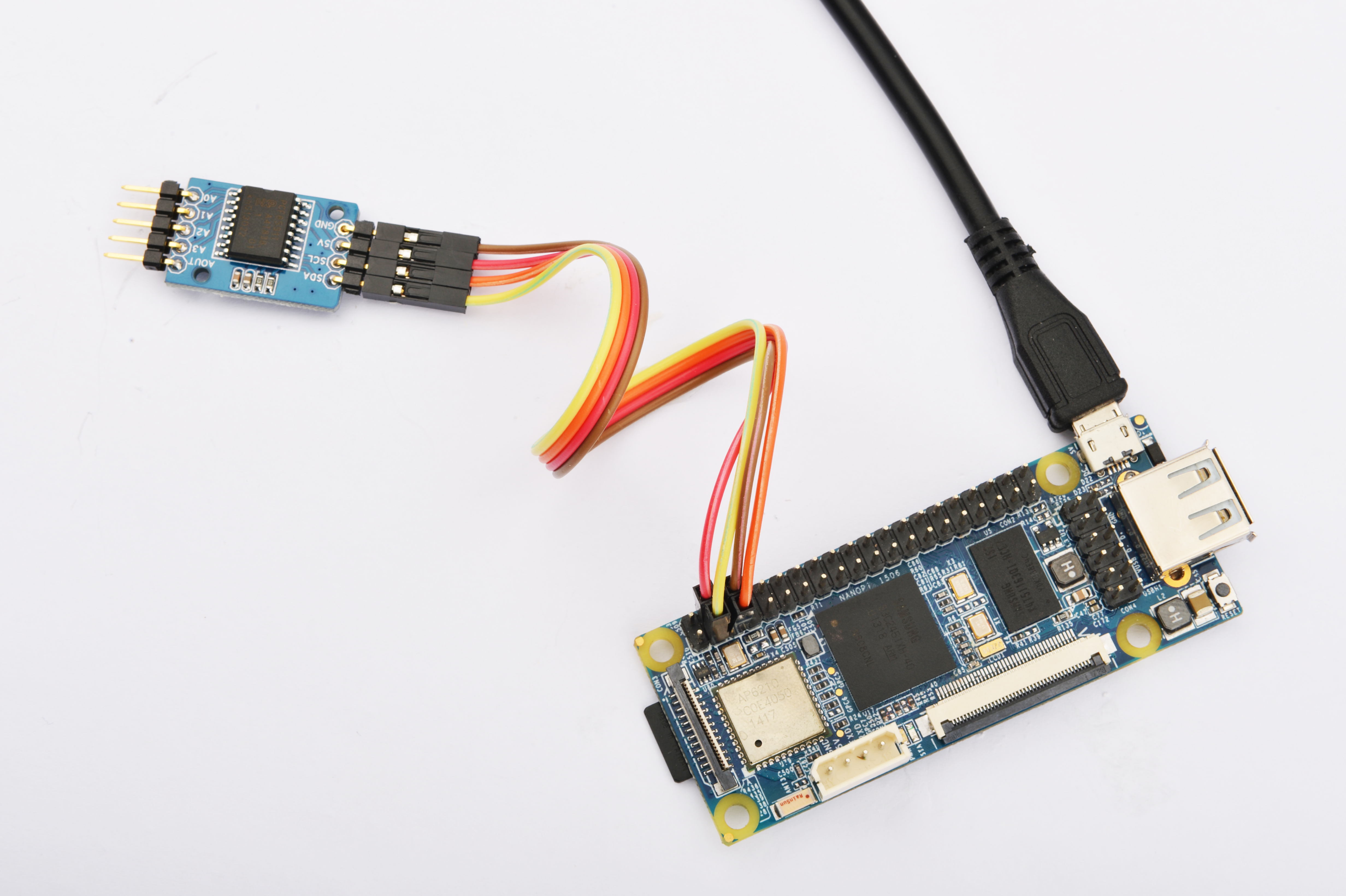
参考下图连接模块Matrix-Analog_to_Digital_Converter和NanoPi

连接说明:
| Matrix-Analog_to_Digital_Converter | NanoPi |
| SDA | Pin3 |
| SCL | Pin5 |
| 5V | Pin4 |
| GND | Pin6 |
5.3 编译测试程序
进入Matrix代码仓库,切换到nanopi分支
$ cd matrix
$ git checkout nanopi
编译Matrix配件代码
$ make CROSS_COMPILE=arm-linux- clean
$ make CROSS_COMPILE=arm-linux-
$ make CROSS_COMPILE=arm-linux- install
注意:请确保你的主机PC当前使用的交叉编译器为NanoPi-Debian配套的arm-linux-gcc-4.4.3。
编译出来的库文件位于install/lib目录下,而测试程序则位于install/usr/bin目录下,模块Matrix-Analog_to_Digital_Converter对应的测试程序为matrix-analog_to_digital_converter。
5.4 运行测试程序
拷贝库文件和测试程序到NanoPi的文件系统上
$ cp install/usr/bin/* nanopi_rootfs/usr/bin/
$ cp install/lib/* nanopi_rootfs/lib/ -d
然后启动NanoPi,在Debian的shell终端中执行如下命令运行模块Matrix-Analog_to_Digital_Converter的测试程序
注意:此模块并不支持热插拔,启动系统前需要确保硬件正常连接。
$ matrix-analog_to_digital_converter5.5 代码展示
int main(int argc, char ** argv)
{
    int devFD;
    int data, channel, mode;

    if ((devFD = pcf8591Init()) == -1) {
        printf("Fail to init pcf8591\n");
        return -1;
    }

    if (pcf8591SetCtrl(devFD, PCF8591_INIT_AD_CONTROL) == -1) {
        printf("Fail to Set pcf8591 control AD\n");
        pcf8591DeInit(devFD);
        return -1;
    }

    mode = 0;
    printf("pcf8591 working as AD in mode%d\n",mode);
    for (channel = PCF8591_AIN_CHANNEL0; channel <= PCF8591_AIN_CHANNEL3; channel++) {
        data = pcf8591Read(devFD, mode, channel);
        printf("Channel%d's value: %d\n",channel,data);
    }

    pcf8591DeInit(devFD);
    return 0;
}
6 与Tiny4412连接使用
6.1 准备工作
参考Tiny4412光盘里的《友善之臂Ubuntu使用手册》,在Tiny4412上运行UbuntuCore系统,然后在主机PC上安装并使用相应的编译器。
注意:只能使用Tiny4412SDK-1506的底板。
6.2 硬件连接
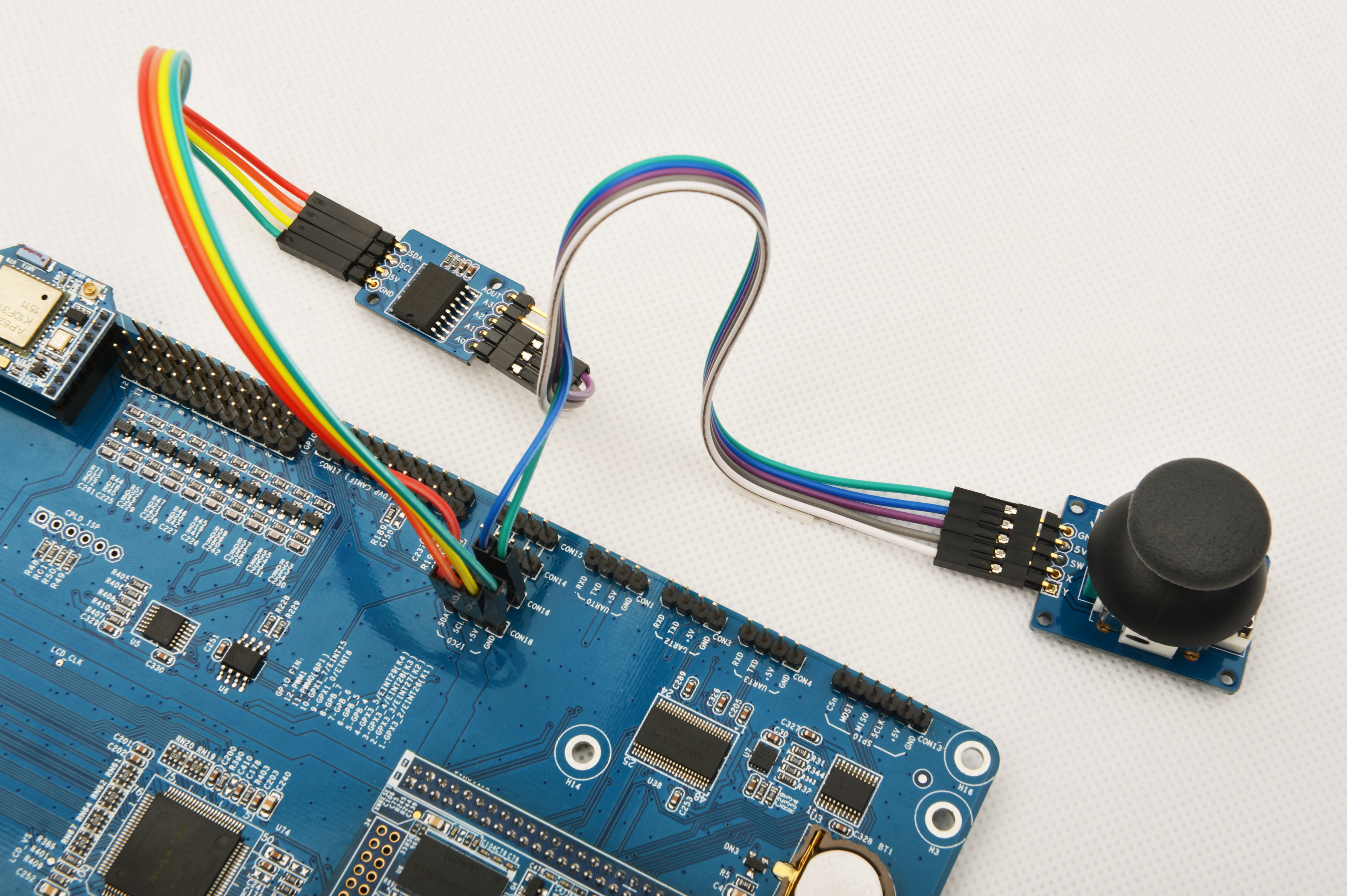
参考下图连接模块Matrix-Analog_to_Digital_Converter和Tiny4412

连接说明:
| Matrix-Analog_to_Digital_Converter | NanoPi |
| SDA | CON18 SDA |
| SCL | CON18 SCL |
| 5V | CON18 5V |
| GND | CON18 GND |
6.3 编译测试程序
进入Matrix代码仓库,切换到tiny4412分支
$ cd matrix
$ git checkout tiny4412
编译Matrix配件代码
$ make CROSS_COMPILE=arm-linux-gnueabihf- clean
$ make CROSS_COMPILE=arm-linux-gnueabihf-
$ make CROSS_COMPILE=arm-linux-gnueabihf- install
注意:请确保你的主机PC当前使用的交叉编译器为Tiny4412-UbuntuCore配套的arm-linux-gnueabihf-gcc-4.7.3。
编译出来的库文件位于install/lib目录下,而测试程序则位于install/usr/bin目录下,模块Matrix-Analog_to_Digital_Converter对应的测试程序为matrix-analog_to_digital_converter。
6.4 运行测试程序
拷贝库文件和测试程序到Tiny4412的UbuntuCore的文件系统上
$ cp install/usr/bin/* tiny4412_rootfs/usr/bin/
$ cp install/lib/* tiny4412_rootfs/lib/ -d
然后启动Tiny4412,在UbuntuCore的shell终端中执行如下命令运行模块Matrix-Analog_to_Digital_Converter的测试程序
$ matrix-analog_to_digital_converter6.5 代码展示
int main(int argc, char ** argv)
{
    int devFD;
    int data, channel, mode;

    if ((devFD = pcf8591Init()) == -1) {
        printf("Fail to init pcf8591\n");
        return -1;
    }

    if (pcf8591SetCtrl(devFD, PCF8591_INIT_AD_CONTROL) == -1) {
        printf("Fail to Set pcf8591 control AD\n");
        pcf8591DeInit(devFD);
        return -1;
    }

    mode = 0;
    printf("pcf8591 working as AD in mode%d\n",mode);
    for (channel = PCF8591_AIN_CHANNEL0; channel <= PCF8591_AIN_CHANNEL3; channel++) {
        data = pcf8591Read(devFD, mode, channel);
        printf("Channel%d's value: %d\n",channel,data);
    }

    pcf8591DeInit(devFD);
    return 0;
}
7 与RaspberryPi连接使用
8 与Arduino连接使用
9 相关资料

