NanoPi M1 Plus
Contents
- 1 Introduction
- 2 Hardware Spec
- 3 Diagram, Layout and Dimension
- 4 Get Started
- 5 Work with Debian
- 5.1 Run Debian
- 5.2 Extend TF Card's rootfs Section
- 5.3 Ethernet Connection
- 5.4 Wireless Connection
- 5.5 Login to Debian via VNC and SSH
- 5.6 HDMI Audio Output
- 5.7 Test GPU
- 5.8 Test VPU
- 5.9 Test USB WiFi
- 5.10 Connect NanoPi M1 Plus to DVP Camera CAM500B
- 5.11 Connect NanoPi M1 Plus to USB Camera(FA-CAM202)
- 5.12 Use OpenCV to Access Camera
- 5.13 Check CPU's Working Temperature
- 5.14 Check System Information with Rpi-Monitor
- 6 Make Your Own Debian
- 7 Android系统的使用
- 8 如何编译Android系统
- 9 更多OS
- 10 3D打印文件下载
- 11 NanoPi M1 Plus初学者入门开发教程
- 12 资源链接
- 13 更新日志
1 Introduction
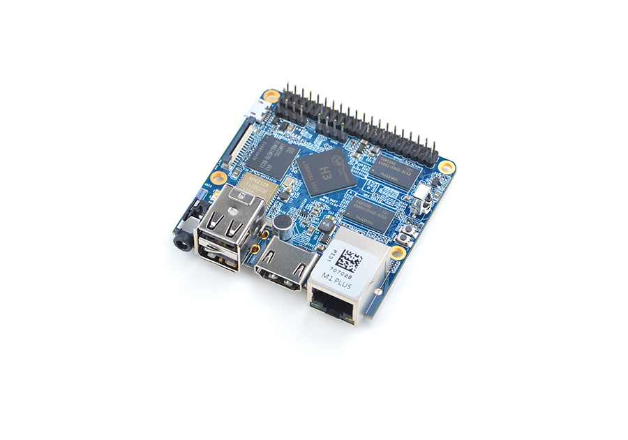
- The NanoPi M1 Plus is designed and developed by FriendlyElec for professionals, enterprise users, makers and hobbyists. It is only two thirds the size of a Raspberry Pi. FriendlyElec has made a Debian, Ubuntu-MATE, Ubuntu-Core and Android images ready for it.
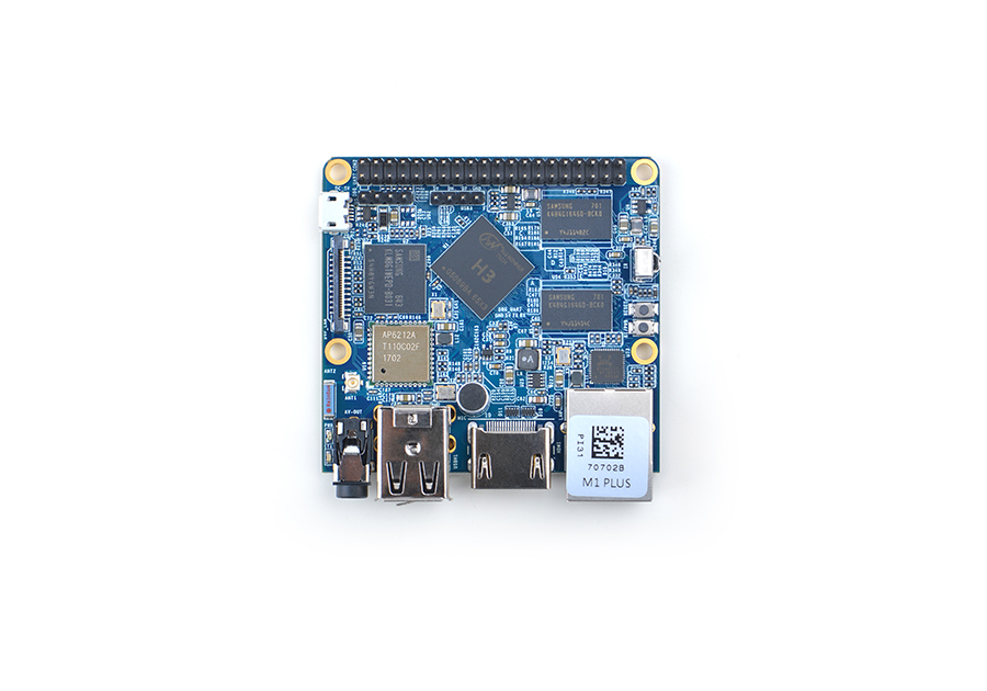
- The NanoPi M1 Plus uses the Allwinner H3 Soc. It integrates Gbps Ethernet, IR receiver, video/audio output, WiFi & Bluetooth, onboard microphone and supports DVP/Camera/HDMI and CVBS. It has a serial debug port. Its GPIO pins are compatible with those of a Raspberry Pi.
2 Hardware Spec
- CPU: Allwinner H3, Quad-core Cortex-A7@1.2GHz
- GPU: Mali400MP2@600MHz,Supports OpenGL ES2.0
- DDR3 RAM: 1GB
- eMMC: 8GB
- Wireless: 802.11 b/g/n
- Bluetooth: 4.0 dual mode
- Antenna Interface: Shared by WiFi and Bluetooth, IPX interface
- Connectivity: 10/100/1000M Ethernet
- Audio: 3.5mm jack/Via HDMI
- Microphone: onboard microphone
- IR: onboard IR receiver
- USB Host: USB 2.0 x 3, 2 x USB Type A and 1 x 2.54mm pitch pin-header
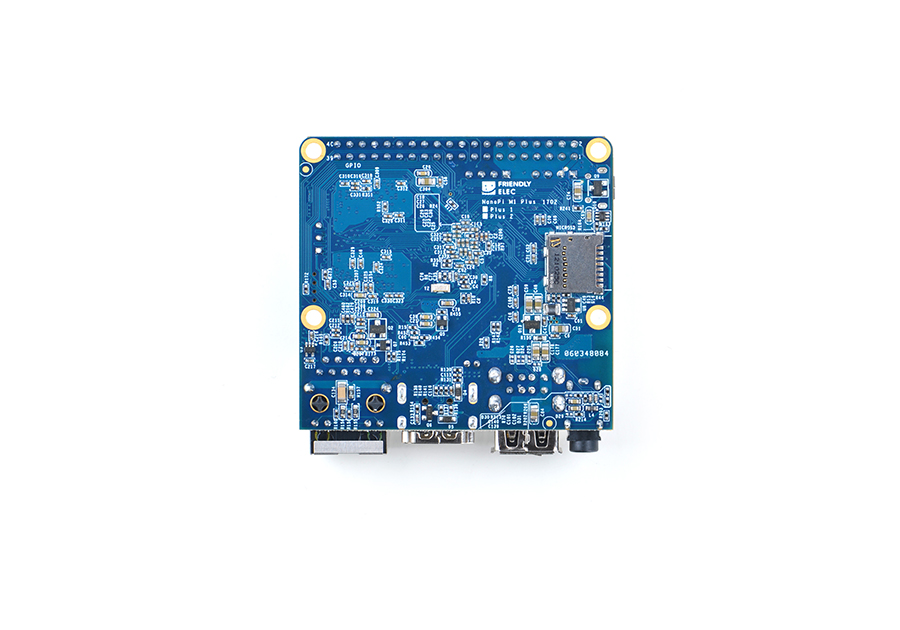
- MicroSD Slot: x1
- MicroUSB: power input and data transmission, OTG
- Audio Output: HDMI 1.4 1080P, CVBS
- DVP Camera Interface: 24pin, 0.5mm pitch FPC seat
- Serial Debug Port: 4Pin, 2.54mm pitch pin-header
- GPIO: 40pin, 2.54mm pitch pin-header, compatible with RasberryPi 2's GPIO. It contains UART, SPI, I2C, I2S/PCM, SPDIF-OUT and IO
- User Button: 1 x Power Button and 1 x Reset Button
- LED: 1 x Power LED and 1 x System Status LED
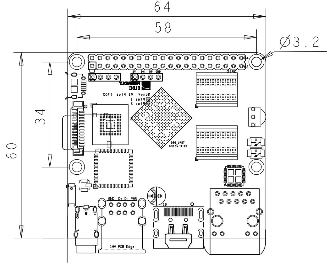
- PCB Dimension: 64 x 60 mm, ENIG
- Power Supply: DC 5V/2A
- OS/Software: u-boot, Debian, Ubuntu-MATE, Ubuntu-Core
3 Diagram, Layout and Dimension
3.1 Layout
- GPIO Pin Description
Pin# Name Linux gpio Pin# Name Linux gpio 1 SYS_3.3V 2 VDD_5V 3 I2C0_SDA 4 VDD_5V 5 I2C0_SCL 6 GND 7 GPIOG11 203 8 UART1_TX/GPIOG6 198 9 GND 10 UART1_RX/GPIOG7 199 11 UART2_TX/GPIOA0 0 12 PWM1/GPIOA6 6 13 UART2_RTS/GPIOA2 2 14 GND 15 UART2_CTS/GPIOA3 3 16 UART1_RTS/GPIOG8 200 17 SYS_3.3V 18 UART1_CTS/GPIOG9 201 19 SPI0_MOSI/GPIOC0 64 20 GND 21 SPI0_MISO/GPIOC1 65 22 UART2_RX/GPIOA1 1 23 SPI0_CLK/GPIOC2 66 24 SPI0_CS/GPIOC3 67 25 GND 26 SPDIF-OUT/GPIOA17 17 27 I2C1_SDA/GPIOA19/PCM0_CLK/I2S0_BCK 19 28 I2C1_SCL/GPIOA18/PCM0_SYNC/I2S0_LRCK 18 29 GPIOA20/PCM0_DOUT/I2S0_SDOUT 20 30 GND 31 GPIOA21/PCM0_DIN/I2S0_SDIN 21 32 NC 33 NC 34 GND 35 NC 36 NC 37 GPIOA9 9 38 NC 39 GND 40 NC
- Debug Port(UART0)
Pin# Name 1 GND 2 VDD_5V 3 UART_TXD0 4 UART_RXD0
- USB Pin Header
Pin# Name 1 5V 2 DM 3 DP 4 GND
- DVP Camera Interface Pin Description
Pin# Name Description 1, 2 SYS_3.3V 3.3V Output, it can be used to power camera modules 7,9,13,15,24 GND Ground, 0V 3 I2C2_SCL I2C clock signal 4 I2C2_SDA I2C data signal 5 GPIOE15 regular GPIO, used to control connected camera modules 6 GPIOE14 regular GPIO, used to control connected camera modules 8 MCLK Clock signals output to camera modules 10 NC Not connected 11 VSYNC vertical synchronization 12 HREF/HSYNC horizontal synchronization 14 PCLK peripheral clock 16-23 Data bit7-0 data bits
- Notes
- SYS_3.3V: 3.3V power output
- VDD_5V: 5V power output5V. When the external device’s power is greater than the MicroUSB’s the external device is charging the board otherwise the board powers the external device.The input range is 4.7V ~ 5.6V
- All pins are 3.3V, output current is 5mA
- For more details refer to the document:NanoPi-M1-Plus-1702-Schematic.pdf
3.2 Board Dimension
- For more details please refer to the document:pcb in dxf format
4 Get Started
4.1 Essentials You Need
Before starting to use your NanoPi M1 Plus get the following items ready
- NanoPi M1 Plus
- MicroSD Card/TF Card: Class 10 or Above, minimum 8GB SDHC
- A DC 5V/2A power is a must
- HDMI monitor
- USB keyboard, mouse and possible a USB hub(or a TTL to serial board)
- A host computer running Ubuntu 14.04 64 bit system
4.2 TF Cards We Tested
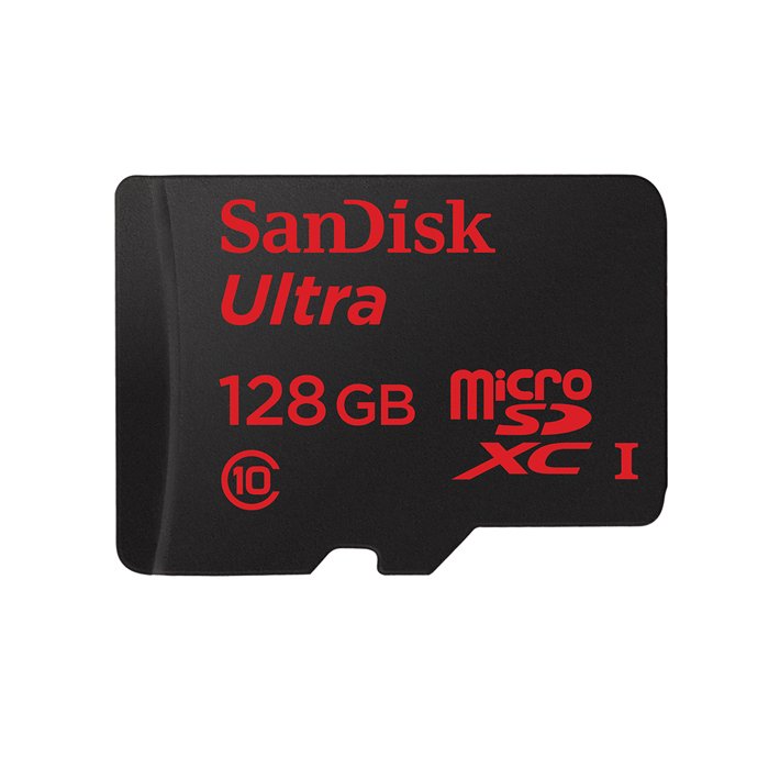
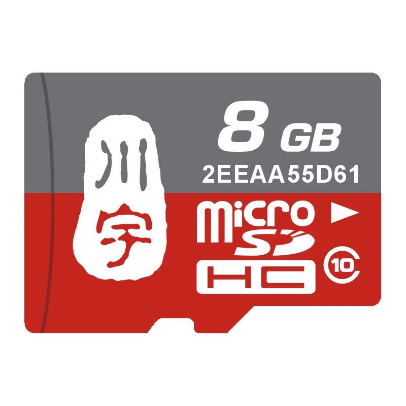
To make your NanoPi M1 Plus boot and run fast we highly recommend you use a Class10 8GB SDHC TF card or a better one. The following cards are what we used in all our test cases presented here:
- SanDisk TF 8G Class10 Micro/SD TF card:
- SanDisk TF128G MicroSDXC TF 128G Class10 48MB/S:
- 川宇 8G C10 High Speed class10 micro SD card:
4.3 Make an Installation TF Card
4.3.1 Download Image Files
Get the following files from here download link to download image files (under the "officail-ROMs" diirectory) and the flashing utility (under the "tools" diirectory):
Image Files nanopi-m1-plus-debian-sd4g.img.zip Debian Image File nanopi-m1-plus-ubuntu-core-qte-sd4g.img.zip Ubuntu core with Qt Embedded nanopi-m1-eflasher-sd8g.img.zip eflasher which can be used to Flash image files to eMMC nanopi-m1-plus-android.img.zip Android Image File Flash Utility win32diskimager.rar Windows utility. Under Linux users can use "dd" PhoenixCard_V310.rar Windows utility for flashing Android image. Attention: the "dd" command under Linux doesn't work for flashing Android image HDDLLF.4.40.exe Windows utility for formatting a TF card
4.3.2 TF Card Systems
4.3.2.1 Make Debian Image Card
- Extract the nanopi-m1-plus-debian-sd4g.img.zip and win32diskimager.rar files. Insert a TF card(at least 8G) into a Windows PC and run the win32diskimager utility as administrator. On the utility's main window select your TF card's drive, the wanted image file and click on "write" to start flashing the TF card.
- Insert this card into your NanoPi M1 Plus' BOOT slot and power on (with a 5V/2A power source). If the green LED is on and the blue LED is blinking this indicates your NanoPi M1 Plus has successfully booted.
Note:you can make a Ubuntu image card in this way too.
4.3.2.2 Make Android Image Card
- On a Windows PC run the HDDLLF.4.40 utility as administrator. Insert a TF card(at least 8G) into this PC and format it. After formatting is done take out the TF card, insert it into the PC again and format it with Windows internal format utility to format it to FAT32. After this formatting is done take out the card.
- Extract the nanopi-m1-plus-android.img.zip and PhoenixCard_V310.rar files. Insert the TF card you made in the previous step into a Windows PC and run the PhoenixCard_V310 utility as administrator. On the utility's main window select your TF card's drive, the wanted image file and click on "write" to start flashing the TF card.
- Insert this card into your NanoPi M1 Plus' BOOT slot and power on (with a 5V/2A power source). If the green LED is on and the blue LED is blinking this indicates your NanoPi M1 Plus has successfully booted.
Note: you must format your TF card before you start making it an Android image card.
4.3.3 Flash image to eMMC with eflasher
- Extract the nanopi-m1-eflasher-sd8g.img.zip and win32diskimager.rar files. Insert a TF card(at least 4G) into a Windows PC and run the win32diskimager utility as administrator. On the utility's main window select your TF card's drive, the wanted image file and click on "write" to start flashing the TF card.
- Insert this card into your NanoPi M1 Plus' BOOT slot and power on (with a 5V/2A power source). If the green LED is on and the blue LED is blinking this indicates your NanoPi M1 Plus has successfully booted.
- Connect the board to an HDMI monitor or an LCD and a USB mouse, and select an OS to start installation.
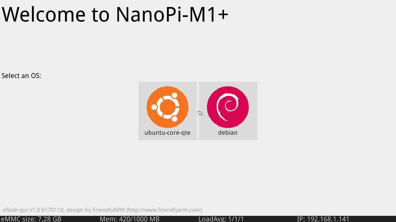
If no monitor is connected you can select an OS by running the following command:
eflasher
Type a number and enter to select an OS, then type "yes" and enter to start installation. After installation is done shutdown the system, take out the TF card, power on your board again and it will boot from eMMC.
5 Work with Debian
5.1 Run Debian
- Insert a TF card with Debian image into your NanoPi M1 Plus, connect the it to an HDMI monitor and a 5V/2A power it will be automatically powered on. If you can see the blue LED flashing it means your board is working and you will see Debain being loaded on the HDMI monitor.
1) If you connect your NanoPi M1 Plus to an HDMI monitor you need to use a USB mouse and a USB keyboard to operate.
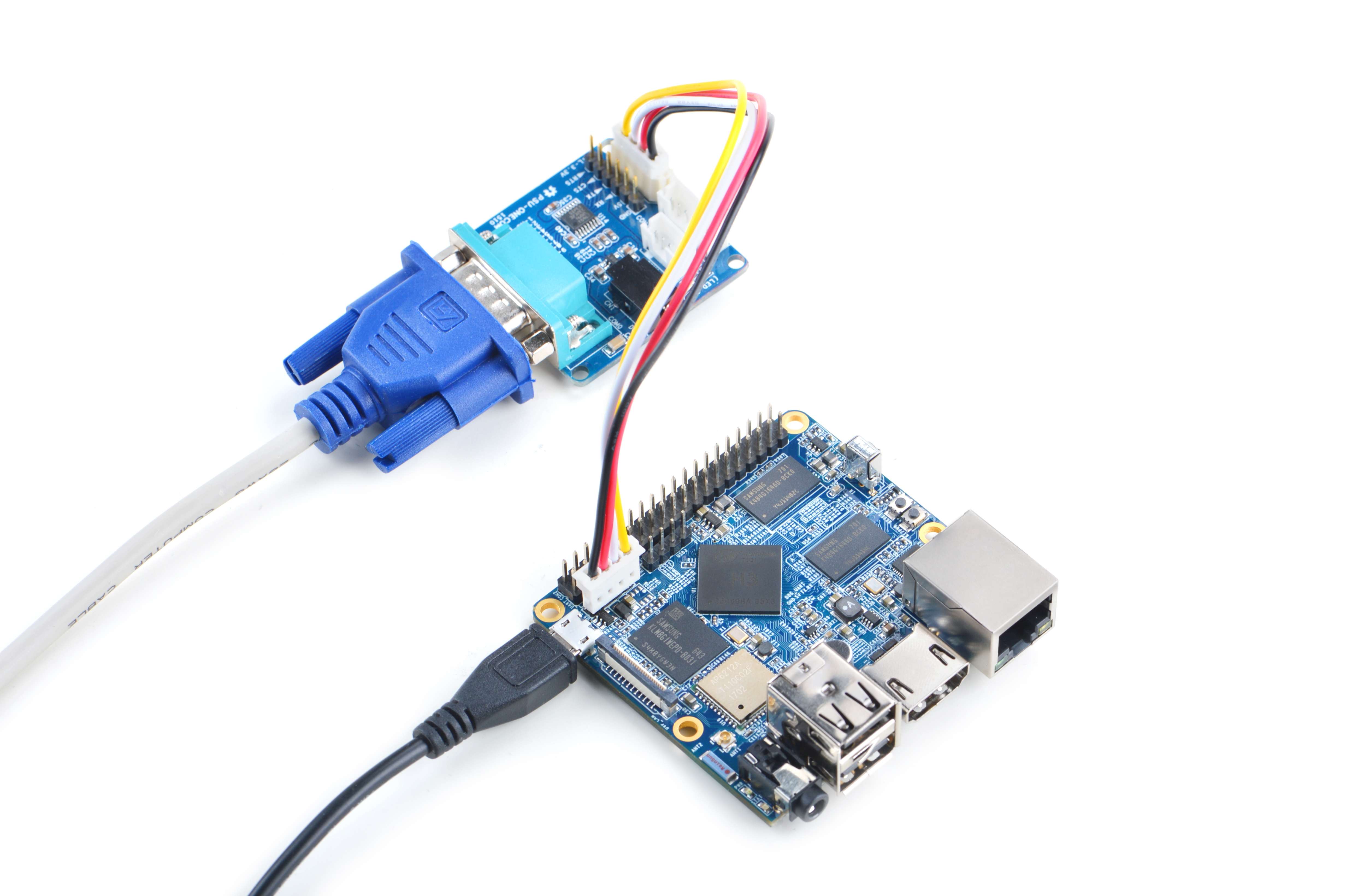
2) If you want to do kernel development you need to use a serial communication board, ie a PSU-ONECOM board, which will allow you to operate the board via a serial terminal.
- Here is a setup where we connect a NanoPi M1 Plus to a PC via the PSU-ONECOM and you can power on your M1 Plus from either the PSU-ONECOM or its MicroUSB:
- The password for both "root" and "fa" is "fa" under Debian.
- Update packages
sudo apt-get update
5.2 Extend TF Card's rootfs Section
When you boot Debian for the first time with your image card your OS will automatically resize the file system and this process takes a relatively long time.After your OS is fully loaded you can check the file system's size by using the following command:
df -h
5.3 Ethernet Connection
If the NanoPi M1 Plus is connected to a network via Ethernet before it is powered on it will automatically obtain an IP after it is powered up. If it is not connected via Ethernet or its DHCP is not activated obtaining an IP will fail and system will hang on for about 15 to 60 seconds
- Setup MAC Address
The NanoPi M1 Plus by default doesn't have a valid MAC address. If the board connects a network successfully it will automatically generate a random MAC in "/etc/network/interfaces.d/eth0". Users can change it to a self-defined valid one:
vi /etc/network/interfaces.d/eth0
Here is the content of a sample configuration file:
auto eth0
allow-hotplug eth0
iface eth0 inet dhcp
hwaddress 76:92:d4:85:f3:0f
The "hwaddress" specifies the MAC address. Here the "76:92:d4:85:f3:0f" is a random MAC. We suggest users change it to a valid one.
Note: when you reset the MAC please make sure your MAC meets IEEE's definition otherwise it will cause unexpected issues.
After you make your change, save, exit and reboot your board or run the following commands to restart the network:
systemctl restart networking
5.4 Wireless Connection
Open the file "/etc/wpa_supplicant/wpa_supplicant.conf" with vi or gedit and append the following lines:
network={
        ssid="YourWiFiESSID"
        psk="YourWiFiPassword"
}
The "YourWiFiESSID" and "YourWiFiPassword" need to be replaced with your actual ESSID and password.
Save, exit and run the following commands your board will be connected to your specified WiFi:
ifdown wlan0
ifup wlan0
If your WiFi password has special characters or you don't want your password saved as plain text you can use "wpa_passphrase" to generate a psk for your WiFi password. Here is how you can do it:
wpa_passphrase YourWiFiESSID
Following the prompt type in your password. If you open the file "/etc/wpa_supplicant/wpa_supplicant.conf" you will find that your password has been updated and you can delete your clear-text password.
5.5 Login to Debian via VNC and SSH
If your NanoPi M1 Plus is not connected to a display device you can login to your NanoPi M1 Plus from a mobile phone or PC. You need to download and install a "VNC Viewer" from here and login to the NanoPi M1 Plus via VNC at port 1. Its default password is "fa123456".
Here is a screenshot which shows how it looks like when users login to a NanoPi M1 Plus from an iPhone via VNC:
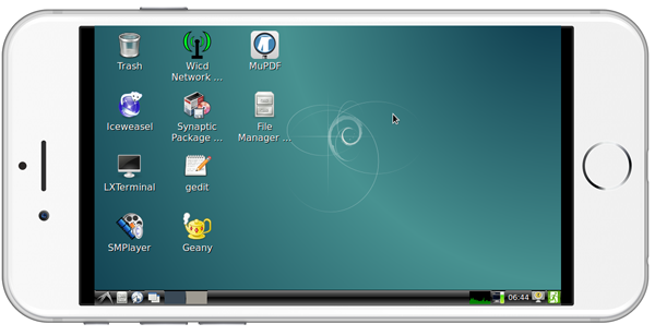
You can login via "SSH -l root 192.168.8.1" and the default password for "root" is "fa". You need to replace "192.168.8.1" with your actual IP address.
5.6 HDMI Audio Output
Our Debian system's default audio output is the 3.5mm audio jack. You can turn on the HDMI audio by editing the /etc/asound.conf file:
pcm.!default {
    type hw
    card 1
    device 0
}

ctl.!default {
    type hw
    card 1
}
card 0 points to the 3.5mm audio jack and card 1 points to the HDMI audio. You need to save your changes and reboot your system to make your changes take effect.
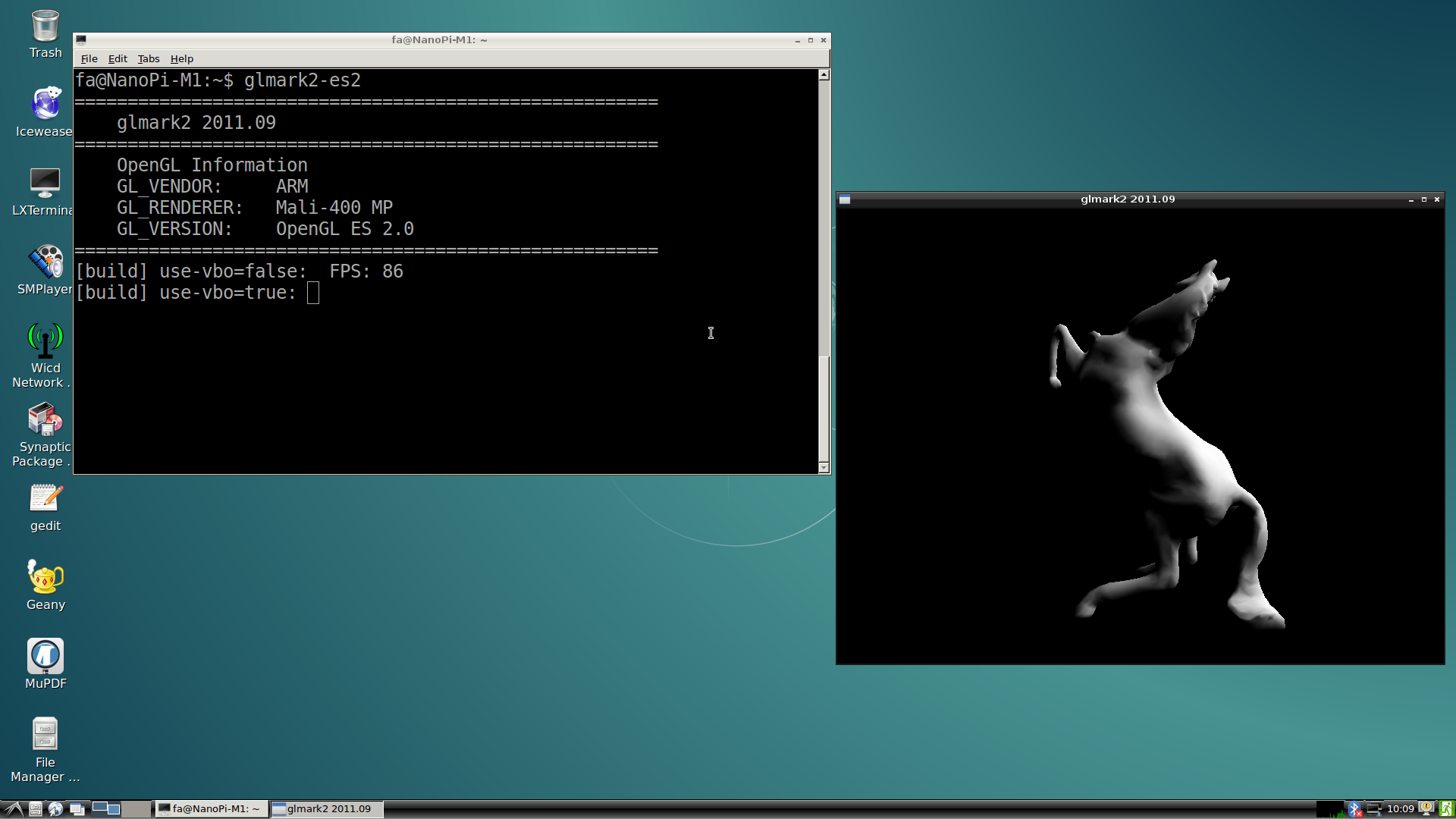
5.7 Test GPU
After Debian loads please login from a terminal and run "glmark2-es2":
glmark2-es2
5.8 Test VPU
Visit this link download link to download the test files under the "test-video" directory
After Debian is loaded login from a terminal and run the following commands:
sudo apt-get install mpv
video_play mpv ./big_buck_bunny_1080p_H264_AAC_25fps_7200K.MP4
In our test it could do hard coding and play 1080P video fluently.
5.9 Test USB WiFi
Our Debian system has support for popular USB WiFi drivers. Many USB WiFi modules are plug and play with our system. Here is a list of models we tested;
Number Model 1 RTL8188CUS 802.11n WLAN Adapter 2 RT2070 Wireless Adapter 3 RT2870/RT3070 Wireless Adapter 4 RTL8192CU Wireless Adapter 5 mi WiFi mt7601
If you NanoPi M1 Plus is connected to a USB WiFi and is powered up you can log into M1 Plus and run the following command to check if the USB WiFi is recognized. If "wlan0" is listed it indicates your USB WiFi has been recognized:
ifconfig -a
Open the /etc/wpa_supplicant/wpa_supplicant.conf file and append the following lines:
network={
        ssid="YourWiFiESSID"
        psk="YourWiFiPassword"
}
The "YourWiFiESSID" and "YourWiFiPassword" need to be replaced with your actual ESSID and password.
Save, exit and run the following commands to connect to your WiFi router:
ifdown wlan0
ifup wlan0
If your WiFi password has special characters or you don't want your password saved as plain text you can use "wpa_passphrase" to generate a psk for your WiFi password. Here is how you can do it:
wpa_passphrase YourWiFiESSID
Following the prompt type in your password and you will get a new password in the /etc/wpa_supplicant/wpa_supplicant.conf file. Now you can replace the existing password in the wlan0 file with the new one.
5.10 Connect NanoPi M1 Plus to DVP Camera CAM500B
The CAM500B camera module is a 5M-pixel camera with DVP interface. For more tech details about it you can refer to Matrix - CAM500B.
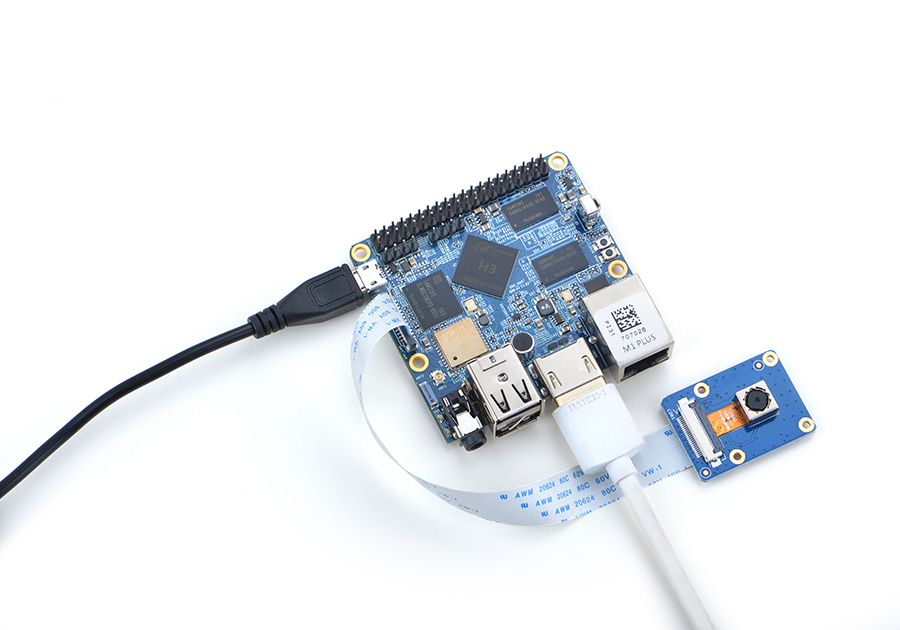
Follow the hardware setup presented in the above picture to connect your NanoPi M1 Plus to a CAM500B. Then boot Debian on your M1 Plus, connect your M1 Plus to a network, log into the board as root and run "mjpg-streamer":
cd /root/mjpg-streamer
make
./start.sh
The mjpg-streamer application is an open source video steam server. After it is successfully started the following messages will be popped up:
 i: Using V4L2 device.: /dev/video0
 i: Desired Resolution: 1280 x 720
 i: Frames Per Second.: 30
 i: Format............: YUV
 i: JPEG Quality......: 90
 o: www-folder-path...: ./www/
 o: HTTP TCP port.....: 8080
 o: username:password.: disabled
 o: commands..........: enabled
In our case the M1 Plus' IP address was 192.168.1.230. We typed 192.168.1.230:8080 in a browser and were able to view the images taken from the camera's. Here is what you would expect to observe:
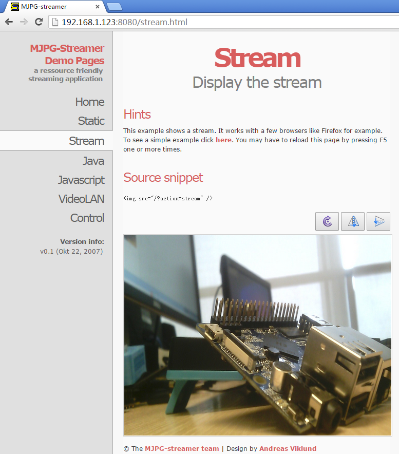
The mjpg-streamer soft-encodes data with libjpeg and you can hard-encode its data with ffmpeg which will greatly increase CPU's efficiency and speed up data encoding:
ffmpeg -t 30 -f v4l2 -channel 0 -video_size 1280x720 -i /dev/video0 -pix_fmt nv12 -r 30 \
        -b:v 64k -c:v cedrus264 test.mp4
By default it records a 30-second video. Typing "q" stops video recording. After recording is stopped a test.mp4 file will be generated.
5.11 Connect NanoPi M1 Plus to USB Camera(FA-CAM202)
The FA-CAM202 is a 200M USB camera.
In this use case the NanoPi M1 Plus runs Debian. Connect your NanoPi M1 Plus to an HDMI monitor. After Debain is fully loaded open a terminal and run the following command:
xawtv 0You will be able to preview with your camera Note: "0" in our case stands for the camera's device name "/dev/video0". You need to use your camera's index in this command.
5.12 Use OpenCV to Access Camera
- The full name of "OpenCV" is Open Source Computer Vision Library and it is a cross platform vision library.
- Make sure your NanoPi M1 is connected to the internet and an HDMI monitor. Boot Debian on the NanoPi M1 and login
- Install OpenCV libraries:
apt-get update
apt-get install libcv-dev libopencv-dev
- Refer to the instructions in the previous sections to make sure the camera works
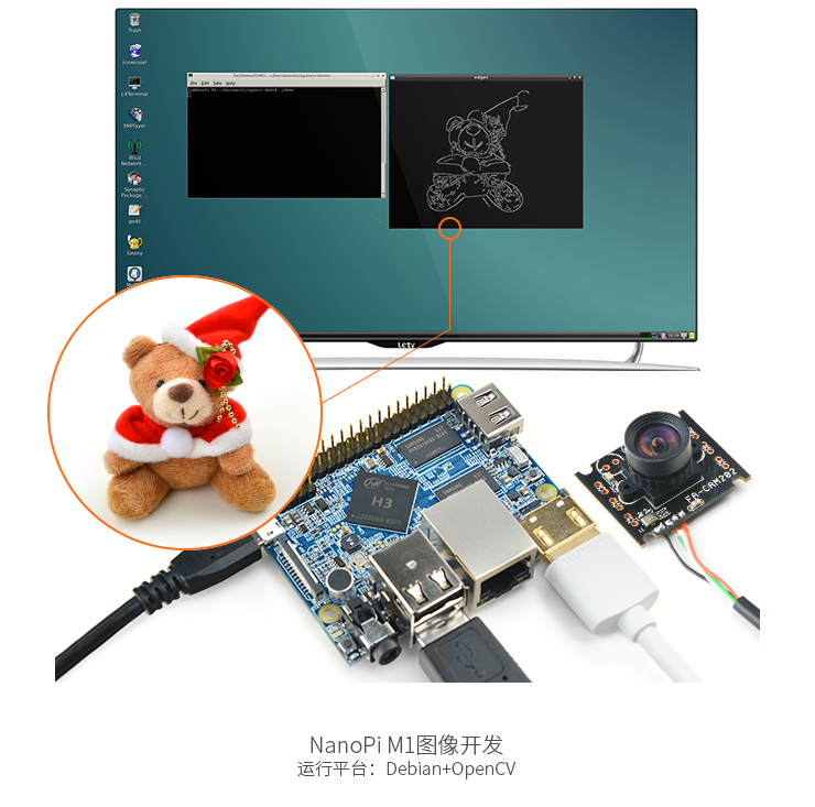
- Compile and run a code sample(Official Code Sample in C++ provided by the OpenCV organization):
cd /home/fa/Documents/opencv-demo
make
./demo
Here is what you expect to observe:
5.13 Check CPU's Working Temperature
You can use the following command to read H3's temperature and frequency
cpu_freq
5.14 Check System Information with Rpi-Monitor
Our Debian contains the Rpi-Monitor utility with which users can check system information and status.
In our case our NanoPi M1's IP was 192.168.1.230 and we typed the following IP in a browser:
192.168.1.230:8888We were directed to the following page:
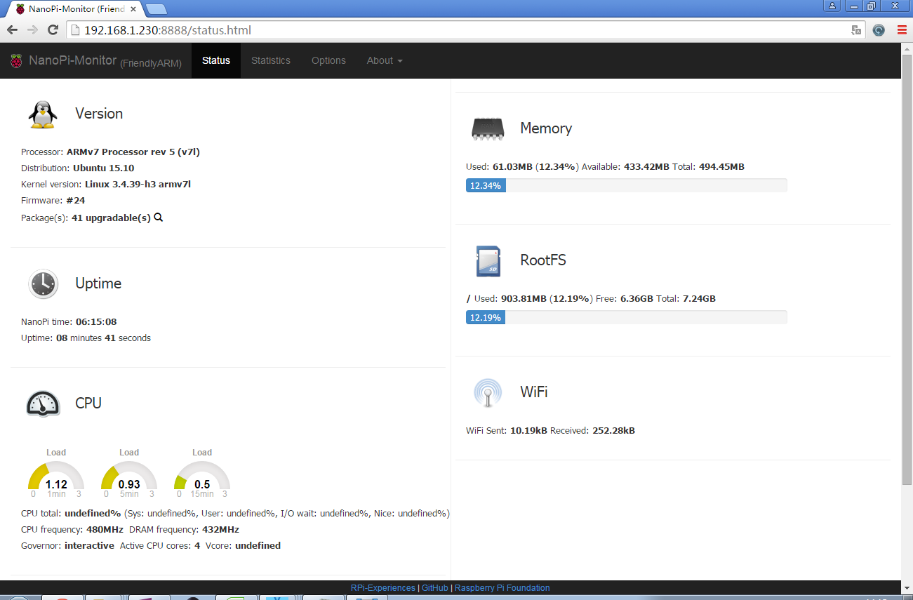
Users can easily check these system information and status.
6 Make Your Own Debian
6.1 Preparations
Visit this link [1] and enter the "sources/nanopi-H3-bsp" directory and download all the source code.Use the 7-zip utility to extract it and a lichee directory and an Android directory will be generated.You can check that by running the following command:
ls ./
android lichee
Or you can get it from our github:
git clone https://github.com/friendlyarm/h3_lichee.git lichee
Note: "lichee" is the project name named by Allwinner for its CPU's source code which contains the source code of U-boot, Linux kernel and various scripts.
6.2 Install Cross Compiler
Visit this site download link, enter the "toolchain" directory, download the cross compiler "gcc-linaro-arm.tar.xz" and copy it to the "lichee/brandy/toochain/" directory.
6.3 编译lichee源码
编译全志 H3 的BSP源码包必须使用64bit的Linux PC系统,并安装下列软件包,下列操作均基于Ubuntu-14.04 LTS-64bit:
sudo apt-get install gawk git gnupg flex bison gperf build-essential \
zip curl libc6-dev libncurses5-dev:i386 x11proto-core-dev \
libx11-dev:i386 libreadline6-dev:i386 libgl1-mesa-glx:i386 \
libgl1-mesa-dev g++-multilib mingw32 tofrodos \
python-markdown libxml2-utils xsltproc zlib1g-dev:i386
为Debian系统编译lichee源码包,进入lichee目录,执行命令:
cd lichee
./build.sh -p sun8iw7p1 -b nanopi-h3
该命令会为Debian系统一次性编译好U-boot、Linux内核和模块。
lichee目录里内置了交叉编译器,当使用build.sh脚本进行源码编译时,会自动使用该内置的编译器,所以无需手动安装编译器。
6.4 打包系统组件
./gen_script.sh -b nanopi-m1-plus
该命令会为U-boot打上全志系列CPU的硬件板级配置补丁,然后所有编译生成的可执行文件(包括U-boot、Linux内核)拷贝到lichee/tools/pack/out/目录以便进行统一管理。
下列命令可以更新TF卡上的U-boot:
./fuse_uboot.sh /dev/sdx
/dev/sdx请替换为实际的TF卡设备文件名。
内核boot.img和驱动模块均位于linux-3.4/output目录下,将boot.img拷贝到TF卡的boot分区的根目录即可更新内核。
6.5 编译U-boot
如果你想单独编译U-boot,可以执行命令:
./build.sh -p sun8iw7p1 -b nanopi-h3 -m uboot
./gen_script.sh -b nanopi-m1-plus
gen_script.sh脚本会为U-boot打上全志系列CPU的硬件板级配置补丁,只有打过补丁文件的U-boot才能烧写到TF卡中正常运行。 执行下列命令更新TF卡上的U-boot:
./fuse_uboot.sh /dev/sdx
/dev/sdx请替换为实际的TF卡设备文件名。
6.6 编译Linux内核
如果你想单独编译Linux内核,可以执行命令:
./build.sh -p sun8iw7p1 -b nanopi-h3 -m kernel
编译完成后内核boot.img和驱动模块均位于linux-3.4/output目录下,将boot.img拷贝到TF卡的boot分区的根目录即可。
6.7 清理lichee源码
./build.sh -p sun8iw7p1_linux -b nanopi-h3 -m clean
7 Android系统的使用
7.1 连接USB WiFi
Android系统目前仅支持型号为rtl8188etv/rtl8188eu的USB WiFi,即插即用。
7.2 使用红外遥控器(RC-100)
启动Android系统后,可用红外遥控器(型号为RC-100)进行远程操控。
RC-100上的按键功能如下:
按键名称 按键功能 POWER 开机/关机 F1 搜索 F2 打开浏览器 F3 进入/退出鼠标模式 UP 向上移动 DOWN 向下移动 LEFT 向左移动 RIGHT 向右移动 OK 确认 音量- 减小音量 音量静音 静音 音量+ 增大音量 SETTING 打开设置 HOME 回到主界面 BACK 返回上一个界面
Android系统第一次启动时,需要点击屏幕上的按钮完成教学示范,用户可以按下 F3 进入鼠标模式,然后配合上下左右和OK按键完成教学操作。
7.3 播放4K视频
访问此处下载地址的test-video目录,下载4K视频文件4K-Chimei-inn-60mbps.mp4,将其拷贝到SD卡或者U盘上。
在M1+上启动并运行Android系统,将带有视频文件的SD卡或者U盘接到M1+上,通过文件浏览器ESFileExplorer找到视频文件,点击视频文件并选择使用系统自带应用Gallery播放视频,即可观看影片。
经测试,将视频文件拷贝到U盘播放效果会更佳。
8 如何编译Android系统
8.1 准备工作
访问此处下载地址的sources/nanopi-h3-bsp目录,下载所有压缩文件,使用7-Zip工具解压后得到lichee目录和android目录,请务必保证这2个目录位于同一个目录中,如下:
ls ./
android lichee
也可以从github上克隆lichee源码:
git clone https://github.com/friendlyarm/h3_lichee.git lichee
注:lichee是全志为其CPU的板级支持包所起的项目名称,里面包含了U-boot,Linux等源码和众多的编译脚本。
编译全志 H3 的BSP源码包必须使用 64bit 的Linux系统,并安装下列软件包,下列操作均基于Ubuntu-14.04 LTS-64bit:
sudo apt-get install gawk git gnupg flex bison gperf build-essential \
zip curl libc6-dev libncurses5-dev:i386 x11proto-core-dev \
libx11-dev:i386 libreadline6-dev:i386 libgl1-mesa-glx:i386 \
libgl1-mesa-dev g++-multilib mingw32 tofrodos \
python-markdown libxml2-utils xsltproc zlib1g-dev:i386
8.2 安装交叉编译器
访问此处下载地址的toolchain目录,下载交叉编译器压缩包gcc-linaro-arm.tar.xz,然后将该压缩包放置在lichee/brandy/toochain/目录下即可,无需解压。
8.3 编译Android
- 搭建编译环境
搭建编译Android的环境建议使用64位的Ubuntu-14.04 LTS-64bit,安装需要的包即可。
sudo apt-get install bison g++-multilib git gperf libxml2-utils make python-networkx zip
sudo apt-get install flex libncurses5-dev zlib1g-dev gawk minicom
更多说明可查看:android_initializing。
- 安装JDK
使用JDK1.6.0_45版本,下载和安装说明请查看Oracle官方网址:Oracle JDK ,这里假设JDK已经成功安装到路径/usr/lib/jvm/下。
- 编译系统
cd lichee
export PATH=/usr/lib/jvm/jdk1.6.0_45/bin:$PATH
./gen_android_img.sh -b nanopi-m1-plus -t android
上述命令会编译lichee目录和android目录,编译完成后会在lichee/tools/pack/目录下生成Android系统固件sun8iw7p1_android_nanopi-h3_uart0.img。
8.4 清理lichee源码
./build.sh -p sun8iw7p1_android -b nanopi-h3 -m clean
9 更多OS
10 3D打印文件下载
- NanoPi M1 Plus 3D打印外壳:[2]
11 NanoPi M1 Plus初学者入门开发教程
- 《硬件编程开发教程》点击下载
12 资源链接
- H3芯片手册 Allwinner_H3_Datasheet_V1.2.pdf
- 模块介绍以及开发文档:
- 按键模块
- LED模块
- 模数转换
- 继电器模块
- 三轴重力加速度模块
- 三轴数字指南针模块
- 温度传感器模块
- 温湿度传感器模块
- 蜂鸣器
- 摇杆模块(Joystick)
- I2C(PCF8574)+LCD1602
- 声音传感器
- 超声波模块
- GPS模块
- 迷你扩展板Matrix - Compact Kit
- 火焰传感器
- CAM500 500万像素摄像头
- 滚珠开关模块
- 2'8 SPI Key TFT 2.8寸spi液晶屏
- 红外计数模块
- 红外接收模块
- 电机驱动器模块
- MQ-2 烟雾传感器模块
- MQ-3 气体传感器
- 单点电容式数字触摸传感器模块
- 光敏电阻模块
- 电位器模块
- 压力传感器模块
- RGB LED
- RTC模块
- Rotary Encoder
- 土壤湿度检测传感器模块
- 热敏电阻模块
- USB WiFi
- 水位/水滴识别检测传感器模块
13 更新日志
13.1 2017-02-04
- 修复Debian系统和Ubuntu-Core系统USB WiFi无法使用的问题;
- 将Ubuntu-Core系统的版本号从15.10升级到16.04;
