Difference between revisions of "Mini Shield for NanoPi Duo"
(→Hardware Spec) |
(→Hardware Setup) |
||
| Line 111: | Line 111: | ||
A NanoPi Duo can be mounted on a Mini Shield. Here is a hardware setup diagram:<br> | A NanoPi Duo can be mounted on a Mini Shield. Here is a hardware setup diagram:<br> | ||
[[File:Mini Shield for NanoPi Duo.jpg|frameless|600px|Mini Shield for NanoPi Duo_NanoPi_Duo]] | [[File:Mini Shield for NanoPi Duo.jpg|frameless|600px|Mini Shield for NanoPi Duo_NanoPi_Duo]] | ||
| + | |||
| + | The Mini Shield for NanoPi Duo has an Ethernet port and USB ports<br> | ||
| + | [[File:NanoPi-Duo_USB2LCD.jpg|frameless|450px|NanoPi Duo]]<br> | ||
It can fit into a Raspberry Pi's case. Here is a hardware setup:<br> | It can fit into a Raspberry Pi's case. Here is a hardware setup:<br> | ||
Revision as of 09:53, 9 November 2017
Contents
1 Introduction
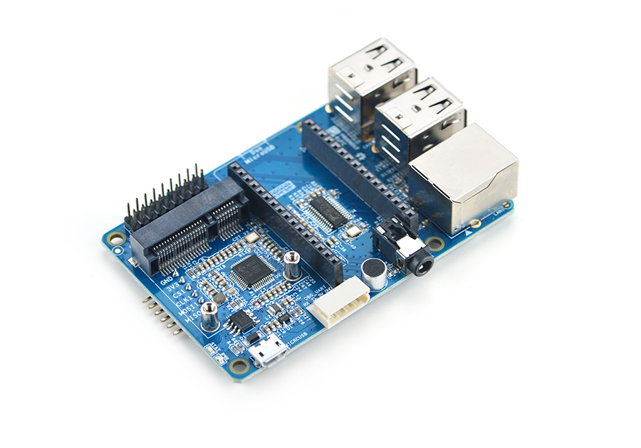
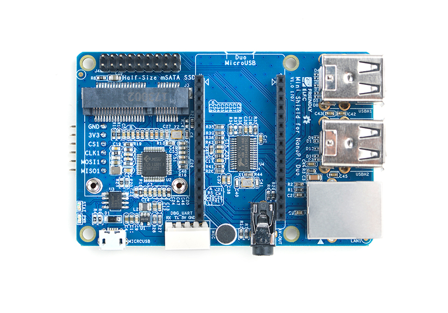
- The Mini Shield for NanoPi Duo is a dedicated carrier board for the NanoPi Duo. It extends Duo's Ethernet, serial port, audio, USB and etc.
- The mini shield has an onboard JMS567 USB to SATA IC and an mSATA interface.
- The mini shield has an onboard FE1.1s which extends four USB Host ports.
- It has a serial port and Ethernet port.
- It has an onboard microphone and a 3.5mm audio jack.
- The mini shield has a 2 x9 Pin header which extends NanoPi Duo's IO pins.
- There is a 6-pin SPI header on the reverse side.
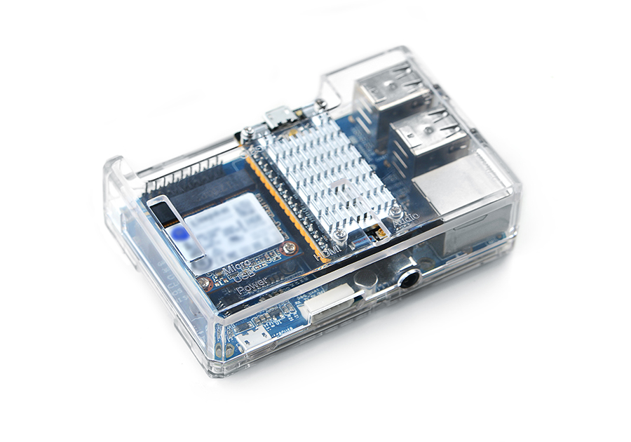
- This shield's dimension and mounting holes' positions are exactly the same as those of a Raspberry Pi therefore it can well fit into a Raspberry Pi's case.
2 Hardware Spec
- its dimension is the same as that of a Raspberry Pi and it can fit into a Pi's case
- 4 x USB Host port
- Serial port and Ethernet port
- Audio input and output
- 2 x 9 Pin GPIO header
- 6 x Pin SPI header
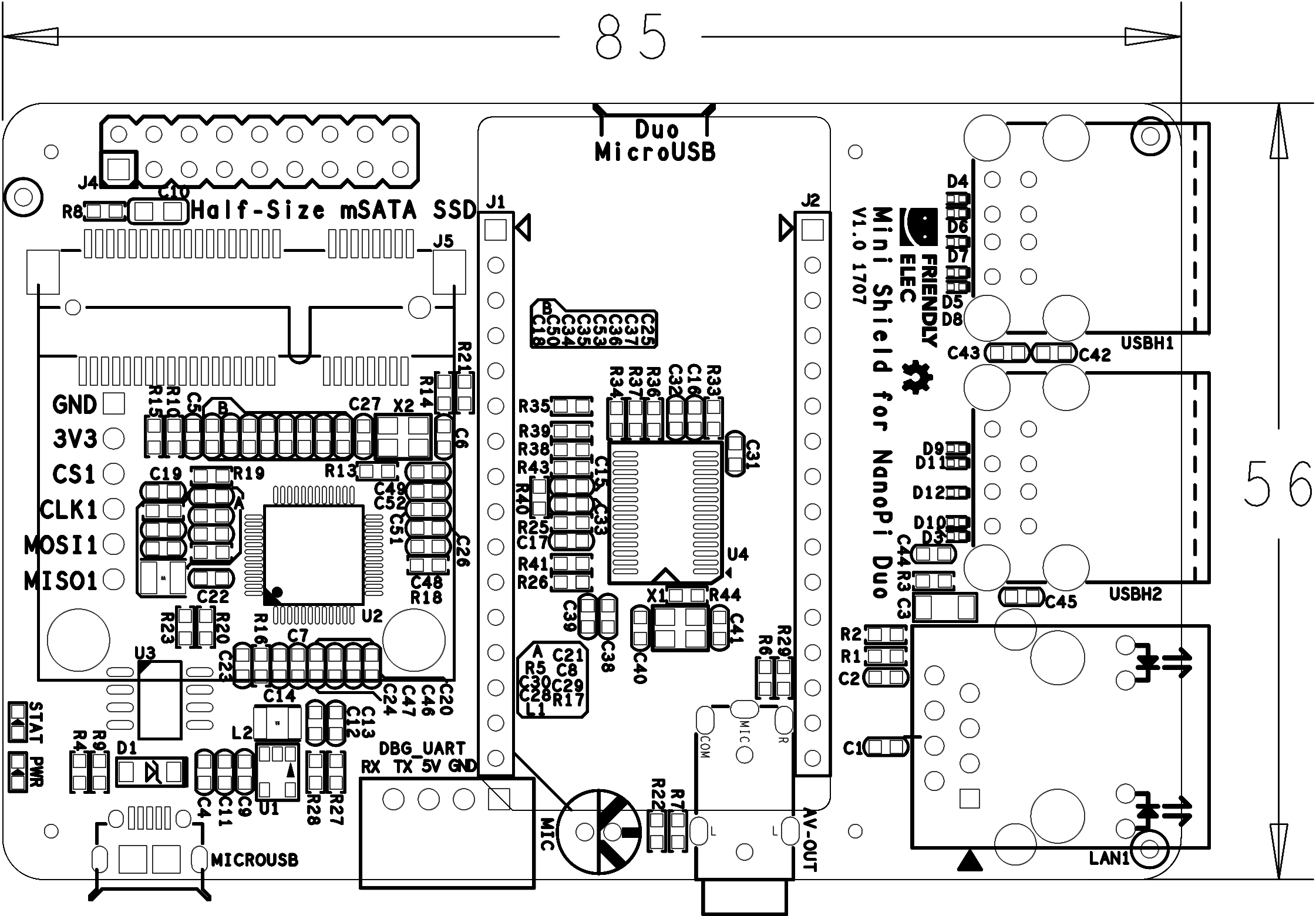
- PCB dimension(mm): 85 x 56
2.1 Diagram, Layout and Dimension
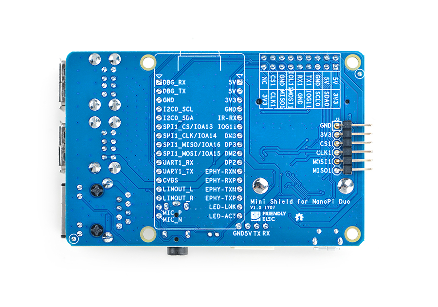
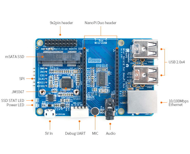
Here is a layout of ports and interfaces. There are detailed descriptions for ports and interfaces on the other side of the board.
- NanoPi Duo Pin-header Pin Description
Number# Name Number# Name 1 VDD_5V 1 DEBUG_RX(UART_RXD0)/GPIOA5/PWM0 2 VDD_5V 2 DEBUG_TX(UART_TXD0)/GPIOA4 3 SYS_3.3V 3 GND 4 GND 4 I2C0_SCL/GPIOA11 5 GPIOL11/IR-RX 5 I2C0_SDA/GPIOA12 6 GPIOG11 6 UART3_TX/SPI1_CS/GPIOA13 7 USB-DM3 7 UART3_RX/SPI1_CLK/GPIOA14 8 USB-DP3 8 UART3_CTS/SPI1_MISO/GPIOA16 9 USB-DM2 9 UART3_RTS/SPI1_MOSI/GPIOA15 10 USB-DP2 10 UART1_RX/GPIOG7 11 EPHY-RXN 11 UART1_TX/GPIOG6 12 EPHY-RXP 12 CVBS 13 EPHY-TXN 13 LINEOUT_L 14 EPHY-TXP 14 LINEOUT_R 15 EPHY-LED-LINK 15 MIC_P 16 EPHY-LED-SPD 16 MIC_N
- 9x2 Pin Header Pin Description
Number# Name Number# Name 1 SYS_3.3V 2 VDD_5V 3 I2C0_SDA / GPIOA12 4 VDD_5V 5 I2C0_SCL / GPIOA11 6 GND 7 GPIOG11 8 UART1_TX / GPIOG6 9 GND 10 UART1_RX / GPIOG7 11 SPI1_MOSI/GPIOA15 12 GPIOL11 13 SPI1_MISO/GPIOA16 14 GND 15 SPI1_CLK/GPIOA14 16 SPI1_CS/GPIOA13 17 SYS_3.3V 18 NC
- 6 Pin SPI Pin Header Pin Description
Number# Name 1 GND 2 SYS_3.3V 3 SPI1_CS/GPIOA13 4 SPI1_CLK/GPIOA14 5 SPI1_MOSI/GPIOA15 6 SPI1_MISO/GPIOA16
3 Hardware Setup
A NanoPi Duo can be mounted on a Mini Shield. Here is a hardware setup diagram:
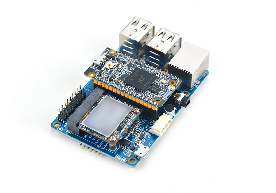
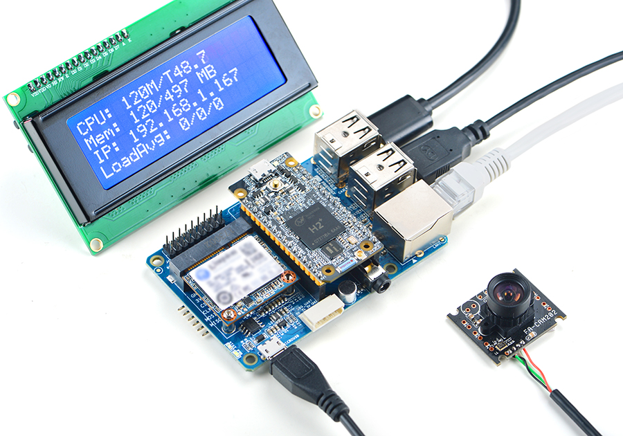
The Mini Shield for NanoPi Duo has an Ethernet port and USB ports
It can fit into a Raspberry Pi's case. Here is a hardware setup:
4 Applications
4.1 Connect SSD to mSATA
Connect an SSD hard disk to the shield's mSATA, power on the board and type the following command to check the SSD's status:
fdisk -l
Here is what you expect to observe:

4.2 Boot System from SSD
A NanoPi-Duo can be booted from the SSD on a Mini Shield for NanoPi Duo. Booting OS from an SSD has the following benefits:
1) faster read/write;
2) much longer life time than a TF card;
3) more reliable than booting from a TF card;
You can install an OS to SSD by using the npi-config utility. Here are the steps to follow:
sudo npi-configEnter the "Boot Options" menu, go to "Boot device" and you will see two options:
1) D1 Hard drive
2) D2 TF card
Select "D1 Hard drive" and proceed with its prompts.
Select "D2 TF card" to boot OS from a TF card.
If your npi-config doesn't have a "Boot device" menu it might be that your npi-config is out of date and you can update it by selecting "Update" in the menu.
4.3 Audio
1. Audio Recording:
arecord -D hw:0,0 -f cd test.wav
Here is what you expect to observe:
![]()
2. Audio Playing:
aplay /root/Music/test.wav
Here is what you expect to observe:

5 Resources
- [Schematic](Schematic - Mini Shield for NanoPi Duo.pdf)
- [Dimension](Dimension - Mini Shield for NanoPi Duo_PCB(dxf))
6 Update Log
6.1 August-16-2017
- Released English Version
