Difference between revisions of "NanoPC-T4"
(→Layout) |
(updated by API) |
||
| (141 intermediate revisions by 4 users not shown) | |||
| Line 14: | Line 14: | ||
* SoC: Rockchip RK3399 | * SoC: Rockchip RK3399 | ||
** CPU: big.LITTLE,Dual-Core Cortex-A72(up to 2.0GHz) + Quad-Core Cortex-A53(up to 1.5GHz) | ** CPU: big.LITTLE,Dual-Core Cortex-A72(up to 2.0GHz) + Quad-Core Cortex-A53(up to 1.5GHz) | ||
| − | ** GPU: Mali-T864 GPU,supports OpenGL ES1.1/2.0/3.0/3 | + | ** GPU: Mali-T864 GPU,supports OpenGL ES1.1/2.0/3.0/3.1, OpenCL, DX11, and AFBC |
** VPU: 4K VP9 and 4K 10bits H265/H264 60fps decoding, Dual VOP, etc | ** VPU: 4K VP9 and 4K 10bits H265/H264 60fps decoding, Dual VOP, etc | ||
| − | * PMU: RK808-D PMIC, cooperated with independent DC/DC, enabling DVFS, | + | * PMU: RK808-D PMIC, cooperated with independent DC/DC, enabling DVFS, sofeware power-down, RTC wake-up, system sleep mode |
* RAM: Dual-Channel 4GB LPDDR3-1866 | * RAM: Dual-Channel 4GB LPDDR3-1866 | ||
* Flash: 16GB eMMC 5.1 Flash | * Flash: 16GB eMMC 5.1 Flash | ||
* Ethernet: Native Gigabit Ethernet | * Ethernet: Native Gigabit Ethernet | ||
| − | * Wi-Fi/BT: 802.11a/b/g/n/ac, Bluetooth 4.1, Wi-Fi and Bluetooth combo module, dual antenna interface | + | * Wi-Fi/BT: 802.11a/b/g/n/ac, Bluetooth 4.1, Wi-Fi and Bluetooth combo module, 2x2 MIMO, dual antenna interface |
* Video Input: one or two 4-Lane MIPI-CSI, dual ISP, up to 13MPix/s,supports simultaneous input of dual camera data | * Video Input: one or two 4-Lane MIPI-CSI, dual ISP, up to 13MPix/s,supports simultaneous input of dual camera data | ||
* Video output | * Video output | ||
| Line 27: | Line 27: | ||
** LCD Interface: one eDP 1.3(4-Lane,10.8Gbps), one or two 4-Lane MIPI-DSI | ** LCD Interface: one eDP 1.3(4-Lane,10.8Gbps), one or two 4-Lane MIPI-DSI | ||
* Audio Out: 3.5mm Dual channel headphone jack, or HDMI | * Audio Out: 3.5mm Dual channel headphone jack, or HDMI | ||
| − | * Audio In: | + | * Audio In: 2-Pin 2.54mm microphone interface |
* USB 2.0: 2 independent native USB 2.0 Host A interfaces | * USB 2.0: 2 independent native USB 2.0 Host A interfaces | ||
* USB 3.0: 1 native USB 3.0 Host A type interface | * USB 3.0: 1 native USB 3.0 Host A type interface | ||
| Line 34: | Line 34: | ||
* microSD Slot x 1 | * microSD Slot x 1 | ||
* 40Pin GPIO Extension ports: | * 40Pin GPIO Extension ports: | ||
| − | ** | + | ** 3 X 3V/1.8V I2C, up to 1 x 3V UART, 1 X 3V SPI, 1 x SPDIF_TX, up to 8 x 3V GPIOs |
** 1 x 1.8V I2S, 3 x 1.8V GPIOs | ** 1 x 1.8V I2S, 3 x 1.8V GPIOs | ||
* ADC: 3 x 1.8V ADC inputs, 5 Pin 2.54mm header | * ADC: 3 x 1.8V ADC inputs, 5 Pin 2.54mm header | ||
| Line 45: | Line 45: | ||
* Power supply: DC 12V/2A | * Power supply: DC 12V/2A | ||
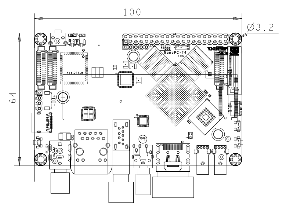
* PCB: Ten Layer, 100 mm x 64 mm | * PCB: Ten Layer, 100 mm x 64 mm | ||
| − | *Ambient Operating Temperature: | + | *Ambient Operating Temperature: -20℃ to 70℃ |
==Software Features== | ==Software Features== | ||
| Line 51: | Line 51: | ||
==Diagram, Layout and Dimension== | ==Diagram, Layout and Dimension== | ||
===Layout=== | ===Layout=== | ||
| − | [[File:NanoPC-T4- | + | [[File:NanoPC-T4-1902-IF-01.jpg |thumb|600px|NanoPC-T4 Layout]] |
* '''40 Pin GPIO Pin Spec''' | * '''40 Pin GPIO Pin Spec''' | ||
::{| class="wikitable" | ::{| class="wikitable" | ||
| Line 63: | Line 63: | ||
|5 || I2C2_SCL(3V) ||6 || GND | |5 || I2C2_SCL(3V) ||6 || GND | ||
|- | |- | ||
| − | |7 || GPIO1_A0(3V) ||8 || | + | |7 || GPIO1_A0(3V) ||8 || GPIO4_C1/I2C3_SCL(3V) |
|- | |- | ||
| − | |9 || GND ||10 || | + | |9 || GND ||10 || GPIO4_C0/I2C3_SDA(3V) |
|- | |- | ||
|11 || GPIO1_A1(3V) ||12 || GPIO1_C2(3V) | |11 || GPIO1_A1(3V) ||12 || GPIO1_C2(3V) | ||
| Line 148: | Line 148: | ||
|22 || GPIO1_B5_TP_RST || 3V output for reseting touch panel, Connect to the reset input of touch panel | |22 || GPIO1_B5_TP_RST || 3V output for reseting touch panel, Connect to the reset input of touch panel | ||
|- | |- | ||
| − | |23 || PWM0_BL || 3V PWM output, for LCD backlight dimming | + | |23 || PWM0_BL || 3V PWM output, for LCD backlight dimming. pull up to VCC3V3_SYS on LCD side. |
|- | |- | ||
|24 || GPIO4_D5_LCD_BL_EN || 3V output for turning on/off the LCD backlight | |24 || GPIO4_D5_LCD_BL_EN || 3V output for turning on/off the LCD backlight | ||
| Line 394: | Line 394: | ||
|} | |} | ||
* '''Cooling Fan interface Pin Spec''' | * '''Cooling Fan interface Pin Spec''' | ||
| − | :: Connector P/N: | + | :: Connector P/N: JST GH connector,BM03B-GHS-TBT |
::{| class="wikitable" | ::{| class="wikitable" | ||
|- | |- | ||
| Line 432: | Line 432: | ||
*'''RTC''' | *'''RTC''' | ||
::RTC backup current is 27uA. | ::RTC backup current is 27uA. | ||
| + | ::Connector P/N: Molex 53398-0271 | ||
:'''Notes''' | :'''Notes''' | ||
::#The Power Jack is the only power input port. All power pins at other ports are output. | ::#The Power Jack is the only power input port. All power pins at other ports are output. | ||
| − | ::#[[Modify_T4_PWRON|How to make T4 start automatically when power is plugged in]] | + | ::#[[Modify_T4_PWRON|How to make T4(1802) start automatically when power is plugged in]] |
| − | ::#For more details refer to | + | ::#For more details refer to [[#Schematic.2C_PCB_CAD_File|Schematics]] |
===Board Dimension=== | ===Board Dimension=== | ||
[[File:NanoPC-T4_1802_Drawing.png|frameless|800px|NanoPC-T4 Dimensions]] | [[File:NanoPC-T4_1802_Drawing.png|frameless|800px|NanoPC-T4 Dimensions]] | ||
| − | ::For more details refer to the CAD document: [http://wiki.friendlyarm.com/wiki/images/b/bc/NanoPC-T4_1802_Drawing%28dxf%29.zip NanoPC-T4_1802_Drawing(dxf).zip] | + | ::For more details refer to the CAD document: [http://wiki.friendlyelec.com/wiki/images/b/bc/NanoPC-T4_1802_Drawing%28dxf%29.zip NanoPC-T4_1802_Drawing(dxf).zip] |
| + | |||
| + | ==Get Started== | ||
| + | ===Essentials You Need=== | ||
| + | Before starting to use your NanoPC-T4 get the following items ready | ||
| + | * NanoPC-T4 | ||
| + | * Type-C cable | ||
| + | * TF Card: Class 10 or Above, minimum 8GB SDHC | ||
| + | * USB to serial adapter(optinal, for debugging or access from PC host) | ||
| + | * A DC 12V/2A power is a must | ||
| + | * HDMI monitor or LCD | ||
| + | * USB keyboard, mouse and possible a USB hub(or a TTL to serial board) | ||
| + | * A host computer running <b>Ubuntu 18.04 64-bit system</b> | ||
| + | ===Install OS=== | ||
| + | {{Downloads-RK3399|NanoPC-T4}} | ||
| + | {{BurnLinuxToSD-Rockchip|NanoPC-T4}} | ||
| + | {{BurnLinuxToEMMC-Rockchip|NanoPC-T4}} | ||
| + | {{RK3399-DebugPort|NanoPC-T4}} | ||
| + | ==Work with Debian11 Desktop== | ||
| + | ===Introduction to Debian11 Desktop=== | ||
| + | {{DebianBullseyeDesktop-Intro|NanoPC-T4}} | ||
| + | {{DebianBullseyeDesktop-Common|NanoPC-T4}} | ||
| + | {{DebianBullseyeDesktop-WithHDMI|NanoPC-T4}} | ||
| + | ==Work with Debian10 Desktop== | ||
| + | * Refer to: | ||
| + | ** [[Debian Buster Desktop|Debian Buster]] | ||
| + | ==Work with FriendlyDesktop== | ||
| + | {{FriendlyDesktop-Intro|NanoPC-T4}} | ||
| + | {{FriendlyDesktop-Contents|NanoPC-T4}} | ||
| + | ===Using NVME SSD on FriendlyDesktop=== | ||
| + | Please see this article: [[Template:How to Initialize and Format New SSD And HDD|How to Initialize and Format New SSD And HDD]]<br /> | ||
| + | ===How to setup WiFiAP on FriendlyDesktop=== | ||
| + | Please see this article: [[Template:Linux-Create-WiFiAP]]<br /> | ||
| + | {{FriendlyCoreGeneral|NanoPC-T4}} | ||
| + | {{FriendlyCoreRunX11Application|NanoPC-T4}} | ||
| + | {{RK3399 Linux mpv|NanoPC-T4}} | ||
| + | ===Change startup LOGO=== | ||
| + | Replace the following two files in the kernel source code directory and recompile the kernel:<br/> | ||
| + | kernel/logo.bmp<br/> | ||
| + | kernel/logo_kernel.bmp<br/> | ||
| + | Or use the script to operate, as shown below: | ||
| + | <syntaxhighlight lang="bash"> | ||
| + | git clone https://github.com/friendlyarm/sd-fuse_rk3399 | ||
| + | cd sd-fuse_rk3399 | ||
| + | convert files/logo.jpg -type truecolor /tmp/logo.bmp | ||
| + | convert files/logo.jpg -type truecolor /tmp/logo_kernel.bmp | ||
| + | LOGO=/tmp/logo.bmp KERNEL_LOGO=/tmp/logo_kernel.bmp ./build-kernel.sh eflasher | ||
| + | LOGO=/tmp/logo.bmp KERNEL_LOGO=/tmp/logo_kernel.bmp ./build-kernel.sh friendlydesktop-arm64 | ||
| + | ./mk-emmc-image.sh friendlydesktop-arm64 | ||
| + | </syntaxhighlight> | ||
| + | ==Features applicable to FriendlyDesktop and FriendlyCore== | ||
| + | {{Linux-RK3399MIPICamera|NanoPC-T4}} | ||
| + | {{RK3399-Linux-Install-Docker|NanoPC-T4}} | ||
| + | {{RK3399 Linux FFmpeg|NanoPC-T4}} | ||
| + | {{How to Initialize and Format New SSD And HDD|NanoPC-T4}} | ||
| + | {{RK3399 Linux PWMFan|NanoPC-T4}} | ||
| + | ===Using 4G Module EC20 on Linux=== | ||
| + | Please see this article: [[How to use 4G Module on NanoPC-T4]]<br /> | ||
| + | ==Buildroot Linux== | ||
| + | {{RK3399 Buildroot Intro|NanoPC-T4}} | ||
| + | <br /> | ||
| + | For a more detailed description of the Buildroot system, please refer to: [[Buildroot|Buildroot]]<br /> | ||
| + | ==Work with Lubuntu== | ||
| + | See here: [[Lubuntu desktop 16.04 for RK3399]]<br /> | ||
| + | Using NVME SSD on Lubuntu: [[Template:How to Initialize and Format New SSD And HDD|How to Initialize and Format New SSD And HDD]]<br /> | ||
| + | {{RK3399-Android8|NanoPC-T4}} | ||
| + | {{RK3399-Android-RemoteController|NanoPC-T4}} | ||
| + | {{RK3399-Android-USBCamera|NanoPC-T4}} | ||
| + | {{RK3399-Android-4G-EC20|NanoPC-T4}} | ||
| + | {{RK3399-Android-SSD|NanoPC-T4}} | ||
| + | {{RK3399 Android PWMFan|NanoPC-T4}} | ||
| + | ==Work with Android7.1== | ||
| + | See here: [[RK3399-Android7|Android7]] | ||
| + | ==How to Compile== | ||
| + | {{Rockchip-DevEnv|NanoPC-T4}} | ||
| + | {{RK3399-BuildFromSource|NanoPC-T4}} | ||
| + | {{RK3399-HWAccess|NanoPC-T4}} | ||
| + | {{RockchipMiscCustome|RK3399}} | ||
| + | {{RockchipCommonLinuxTips|rk3399}} | ||
| + | {{RockchipUnbrick|NanoPC-T4}} | ||
| + | {{MoreOS}} | ||
| + | ==Link to Rockchip Resources== | ||
| + | *Link to Rockchip's resources: https://gitlab.com/friendlyelec/rk3399-nougat/tree/nanopc-t4-nougat/RKDocs | ||
| + | *[http://opensource.rock-chips.com/images/d/d7/Rockchip_RK3399_Datasheet_V2.1-20200323.pdf RK3399 datasheet V2.1] | ||
| + | *[http://opensource.rock-chips.com/images/e/ee/Rockchip_RK3399TRM_V1.4_Part1-20170408.pdf RK3399TRM V1.4] | ||
| + | |||
| + | ==Schematic, PCB CAD File== | ||
| + | *Schematic: [http://wiki.friendlyelec.com/wiki/images/f/f4/NanoPC-T4-1802-Schematic.pdf NanoPC-T4-1802-Schematic.pdf] | ||
| + | *Schematic: [http://wiki.friendlyelec.com/wiki/images/e/e0/NanoPC-T4-1902-Schematic.pdf NanoPC-T4-1902-Schematic.pdf] | ||
| + | *PCB CAD File:[http://wiki.friendlyelec.com/wiki/images/b/bc/NanoPC-T4_1802_Drawing%28dxf%29.zip NanoPC-T4_1802_Drawing(dxf).zip] | ||
| + | |||
| + | ==Update Log== | ||
| + | {{RK3399-UpdateLog|NanoPC-T4}} | ||
Revision as of 09:23, 4 June 2024
Contents
- 1 Introduction
- 2 Hardware Spec
- 3 Software Features
- 4 Diagram, Layout and Dimension
- 5 Get Started
- 6 Access hardware
- 7 Work with Debian11 Desktop
- 7.1 Introduction to Debian11 Desktop
- 7.2 Account & Password
- 7.3 View IP address
- 7.4 Connect to Debian via SSH
- 7.5 Update Software Packages
- 7.6 Install x11vnc Server on Debian for Remote Access
- 7.7 Install the kernel-header package
- 7.8 Change time zone
- 7.9 Change startup LOGO and Wallpaper
- 7.10 Soft Factory Reset
- 7.11 Start the program automatically at startup(For example Kodi)
- 7.12 Disable auto-mounting
- 7.13 Setup Chinese language and Input method
- 7.14 Installing Plex Multimedia Server
- 7.15 Install Docker on Debian
- 7.16 How to test NPU
- 7.17 WiFi Connection
- 7.18 Cancel auto-login
- 7.19 Test OpenGL ES
- 7.20 HDMI/DP LCD Resolution
- 7.21 Adjust HDMI overscan
- 7.22 Chromium web browser
- 7.23 Test hardware encoding
- 8 Work with Debian10 Desktop
- 9 Work with FriendlyDesktop
- 9.1 Account & Password
- 9.2 WiFi Connection
- 9.3 HDMI/DP LCD Resolution
- 9.4 Adjust HDMI overscan
- 9.5 eDP LCD Display Rotation
- 9.6 Test OpenGL ES
- 9.7 4K Video Playing
- 9.8 Work with USB Camera
- 9.9 File Transfer with Bluetooth
- 9.10 Install OpenCV
- 9.11 Develop Qt Applications
- 9.12 WiringPi and Python Wrapper
- 9.13 Switch audio default output device
- 9.14 Play RTSP video stream (or IP Camera)
- 9.15 Chromium web browser
- 9.16 Screen saver and auto sleep related settings
- 9.17 Install Scratch
- 9.18 Install Arduino IDE
- 9.19 Start the program automatically at startup
- 9.20 Login to the desktop as the root user
- 9.21 Using NVME SSD on FriendlyDesktop
- 9.22 How to setup WiFiAP on FriendlyDesktop
- 10 Work with FriendlyCore
- 10.1 Introduction
- 10.2 System Login
- 10.3 Configure System with npi-config
- 10.4 Develop Qt Application
- 10.5 Setup Program to AutoRun
- 10.6 Extend TF Card's Section
- 10.7 Transfer files using Bluetooth
- 10.8 WiFi
- 10.9 Ethernet Connection
- 10.10 WiringPi and Python Wrapper
- 10.11 Custom welcome message
- 10.12 Modify timezone
- 10.13 Select the system default audio device
- 10.14 Change the behavior of the PWM fan
- 10.15 Run the X11 application
- 10.16 Mpv hardware decoding video player
- 10.17 Change startup LOGO
- 11 Features applicable to FriendlyDesktop and FriendlyCore
- 12 Connect NVME SSD High Speed Hard Disk
- 13 Buildroot Linux
- 14 Work with Lubuntu
- 15 Work with Android 8.1
- 15.1 Connect MIPI Camera to NanoPC-T4
- 15.2 Use dual MIPI camera preview and video
- 15.3 Change system language
- 15.4 Android8.1 hardware access
- 15.5 Android Neural Networks SDK Sample
- 15.6 Using the adb
- 15.7 HDMI resolution and overscan setting
- 15.8 Screen rotation
- 15.9 Hide Navigation bar
- 15.10 Switch audio output channel
- 15.11 Adjust the volume of the recording
- 15.12 Custom logo and boot animation
- 15.13 Remove Google Framework
- 15.14 Navigate Android with Remote Control
- 15.15 Work with USB Camera to Take Pictures and Record Video
- 15.16 Using 4G Module EC20 on Android
- 15.17 Using SSD on Android
- 15.18 Fan speed setting
- 16 Work with Android7.1
- 17 How to Compile
- 17.1 Setup Development Environment
- 17.2 Build Openwrt/Friendlywrt
- 17.3 Build Buildroot
- 17.4 Build Other Linux
- 17.5 Build the code using scripts
- 17.6 Building AOSP from source
- 18 Access hardware
- 19 Backup rootfs and create custom SD image (to burn your application into other boards)
- 20 Configuring kernel command line parameters (only support for kernel4.4)
- 21 Common Linux-based operating system operations
- 22 Unbricking Method
- 23 More OS Support
- 24 Link to Rockchip Resources
- 25 Schematic, PCB CAD File
- 26 Update Log
- 26.1 2024-04-21
- 26.2 2024-03-15
- 26.3 2024-01-31
- 26.4 2023-12-01
- 26.5 2023-10-31
- 26.6 2023-07-01
- 26.7 2023-05-26
- 26.8 2023-05-21
- 26.9 2023-04-26
- 26.10 2023-02-10
- 26.11 2023-01-09
- 26.12 2022-12-04
- 26.13 2022-09-06
- 26.14 2022-08-19
- 26.15 2022-08-03
- 26.16 2022-07-27
- 26.17 2022-07-04
- 26.18 2021-12-02
- 26.19 2021-10-29
- 26.20 2021-08-31
- 26.21 2021-03-11
- 26.22 2020-12-24
- 26.23 2020-12-17
- 26.24 2020-10-27
- 26.25 2020-09-27
- 26.26 2020-09-16
- 26.27 2020-08-17
- 26.28 2020-07-10
- 26.29 2020-06-23
- 26.30 2020-03-24
- 26.31 2019-12-27
- 26.32 2019-09-26
- 26.33 2019-09-03
- 26.34 2019-07-18
- 26.35 2019-06-25
- 26.36 2019-05-23
- 26.37 2019-05-11
- 26.38 2019-03-08
- 26.39 2018-12-19
- 26.40 2018-11-12
- 26.41 2018-09-21
- 26.42 2018-09-05
1 Introduction
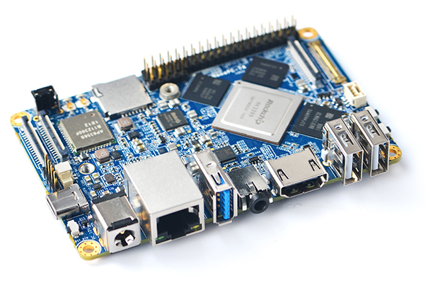
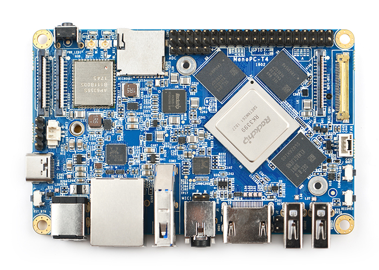
- The NanoPC-T4 is by far the smallest RK3399 based high-performance ARM board with popular ports and interfaces. Its software is fully open source. It is as small as 100 x 64 mm. It has 4GB LPDDR3 RAM, 16GB eMMC flash, onboard 2.4G & 5G dual-band WiFi module and a full standard M.2 PCIe interface which supports an NVME SSD high-speed hard drive. The NanoPC-T4 supports GPU and VPU acceleration and works with Android 7.1 and Lubuntu Desktop.
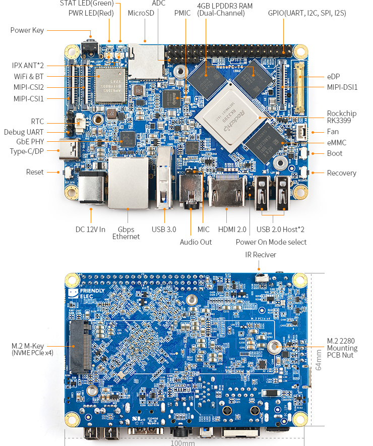
- The NanoPC-T4 has a MIPI-CSI dual camera interface, a MIPI-DSI and an eDP display interfaces, and an HDMI 2.0 interface. It has Type-C/DP, USB 3.0, USB2.0, MicroSD, Gbps Ethernet port, 3.5mm audio jack, infrared receiver, AD input, serial debug interface and a 40Pin RPi compatible connector.
- The RK3399 SoC has an internal Mali-T860 GPU which has powerful capabilities of processing 3D and HD H.265/H2.64 video streams. It supports dual camera inputs, dual ISP interface capable of doing image processing up to 13MPix/s. The NanoPC-T4 is a perfect platform for AI and deep learning applications. It can be widely used in advertisement machines, game machines, video conference applications, surveillance systems, clusters, VR/AR applications, machine vision applications and etc.
2 Hardware Spec
- SoC: Rockchip RK3399
- CPU: big.LITTLE,Dual-Core Cortex-A72(up to 2.0GHz) + Quad-Core Cortex-A53(up to 1.5GHz)
- GPU: Mali-T864 GPU,supports OpenGL ES1.1/2.0/3.0/3.1, OpenCL, DX11, and AFBC
- VPU: 4K VP9 and 4K 10bits H265/H264 60fps decoding, Dual VOP, etc
- PMU: RK808-D PMIC, cooperated with independent DC/DC, enabling DVFS, sofeware power-down, RTC wake-up, system sleep mode
- RAM: Dual-Channel 4GB LPDDR3-1866
- Flash: 16GB eMMC 5.1 Flash
- Ethernet: Native Gigabit Ethernet
- Wi-Fi/BT: 802.11a/b/g/n/ac, Bluetooth 4.1, Wi-Fi and Bluetooth combo module, 2x2 MIMO, dual antenna interface
- Video Input: one or two 4-Lane MIPI-CSI, dual ISP, up to 13MPix/s,supports simultaneous input of dual camera data
- Video output
- HDMI: HDMI 2.0a, supports 4K@60Hz,HDCP 1.4/2.2
- DP on Type-C: DisplayPort 1.2 Alt Mode on USB Type-C
- LCD Interface: one eDP 1.3(4-Lane,10.8Gbps), one or two 4-Lane MIPI-DSI
- Audio Out: 3.5mm Dual channel headphone jack, or HDMI
- Audio In: 2-Pin 2.54mm microphone interface
- USB 2.0: 2 independent native USB 2.0 Host A interfaces
- USB 3.0: 1 native USB 3.0 Host A type interface
- USB Type-C: Supports USB3.0 Type-C and DisplayPort 1.2 Alt Mode on USB Type-C
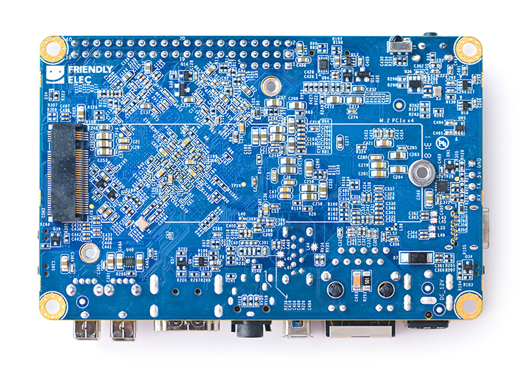
- PCIe: One M.2 M-Key PCIe x4 socket, compatible with PCIe 2.1, Dual operation mode; Onboard M3 PCB nut for mounting M.2 2280 module
- microSD Slot x 1
- 40Pin GPIO Extension ports:
- 3 X 3V/1.8V I2C, up to 1 x 3V UART, 1 X 3V SPI, 1 x SPDIF_TX, up to 8 x 3V GPIOs
- 1 x 1.8V I2S, 3 x 1.8V GPIOs
- ADC: 3 x 1.8V ADC inputs, 5 Pin 2.54mm header
- Debug: one Debug UART, 4 Pin 2.54mm header, 3V level, 1500000bps
- Keys: PowerKey, Reset, MASKROM(BOOT), Recovery
- LED: 1 x power LED and 1 x GPIO Controlled LED
- IR reciver: Onboard IR reciver, Acceptes 38KHz carrier frequency
- RTC Battery: 2 Pin 1.27/1.25mm RTC battery input connector
- Cooling: two 2.5mm PCB nuts for mounting heat sink; 3 Pin 12V cooling fan interface with PWM
- Power supply: DC 12V/2A
- PCB: Ten Layer, 100 mm x 64 mm
- Ambient Operating Temperature: -20℃ to 70℃
3 Software Features
4 Diagram, Layout and Dimension
4.1 Layout
- 40 Pin GPIO Pin Spec
Pin# Assignment Pin# Assignment 1 VCC3V3_SYS 2 VCC5V0_SYS 3 I2C2_SDA(3V) 4 VCC5V0_SYS 5 I2C2_SCL(3V) 6 GND 7 GPIO1_A0(3V) 8 GPIO4_C1/I2C3_SCL(3V) 9 GND 10 GPIO4_C0/I2C3_SDA(3V) 11 GPIO1_A1(3V) 12 GPIO1_C2(3V) 13 GPIO1_A3(3V) 14 GND 15 GPIO1_A4(3V) 16 GPIO1_C6(3V) 17 VCC3V3_SYS 18 GPIO1_C7(3V) 19 SPI1_TXD/UART4_TX(3V) 20 GND 21 SPI1_RXD/UART4_RX(3V) 22 GPIO1_D0(3V) 23 SPI1_CLK(3V) 24 SPI1_CSn0(3V) 25 GND 26 GPIO4_C5/SPDIF_TX(3V) 27 I2C2_SDA(1.8V) 28 I2C2_SCL(1.8V) 29 I2S1_LRCK_RX(1.8V) 30 GND 31 I2S1_LRCK_TX(1.8V) 32 I2S_CLK(1.8V) 33 I2S1_SCLK(1.8V) 34 GND 35 I2S1_SDI0(1.8V) 36 I2S1_SDO0(1.8V) 37 GPIO3_D4(1.8V) 38 GPIO3_D5(1.8V) 39 GND 40 GPIO3_D6(1.8V)
- eDP Interface Pin Spec
- Connector P/N: I-PEX-20455-030E
Pin# Assignment Description 1 GND Signal ground 2 EDP_TX3N eDP data lane 3 negative output 3 EDP_TX3P eDP data lane 3 positive output 4 GND Signal ground 5 EDP_TX2N eDP data lane 2 negative output 6 EDP_TX2P eDP data lane 2 positive output 7 GND Signal ground 8 EDP_TX1N eDP data lane 1 negative output 9 EDP_TX1P eDP data lane 1 positive output 10 GND Signal ground 11 EDP_TX0N eDP data lane 0 negative output 12 EDP_TX0P eDP data lane 0 positive output 13 GND Signal ground 14 EDPAUXP eDP CH-AUX positive differential output 15 EDPAUXN eDP CH-AUX negative differential output 16 GND Signal ground 17 VCC3V3_SYS 3.3V Power output for logic 18 VCC3V3_SYS 3.3V Power output for logic 19 I2C4_SDA 3V I2C data signal, Connect to touch panel 20 I2C4_SCL 3V I2C clock signal, Connect to touch panel 21 GPIO1_C4_TP_INT 3V interrupt input, Connect to the interrupt output of touch panel 22 GPIO1_B5_TP_RST 3V output for reseting touch panel, Connect to the reset input of touch panel 23 PWM0_BL 3V PWM output, for LCD backlight dimming. pull up to VCC3V3_SYS on LCD side. 24 GPIO4_D5_LCD_BL_EN 3V output for turning on/off the LCD backlight 25 GND Backlight ground 26 GND Backlight ground 27 GND Backlight ground 28 VCC12V0_SYS 12V Power output for Backlight Power 29 VCC12V0_SYS 12V Power output for Backlight Power 30 VCC12V0_SYS 12V Power output for Backlight Power
- MIPI-DSI Interface Pin Spec
- 0.5mm FPC connector
Pin# Assignment Description 1, 2, 3 VCC5V0_SYS 5V power output 4 GND Return current path 5 I2C4_SDA 3V I2C data signal, Connect to touch panel 6 I2C4_SCL 3V I2C clock signal, Connect to touch panel 7 GND Return current path 8 GPIO1_C4_TP_INT 3V interrupt input, Connect to the interrupt output of touch panel 9 GND Return current path 10 PWM0_BL 3V PWM output, for LCD backlight dimming 11 GND Return current path 12 GPIO4_D5_LCD_BL_EN 3V output for turning on/off the LCD backlight 13 GPIO4_D6_LCD_RST_H 3V output for reseting the LCD module 14 GPIO1_B5_TP_RST 3V output for reseting touch panel, Connect to the reset input of touch panel 15 GND Return current path 16 MIPI_TX0_D3N MIPI DSI negative differential data line transceiver output 17 MIPI_TX0_D3P MIPI DSI positive differential data line transceiver output 18 GND Return current path 19 MIPI_TX0_D2N MIPI DSI negative differential data line transceiver output 20 MIPI_TX0_D2P MIPI DSI positive differential data line transceiver output 21 GND Return current path 22 MIPI_TX0_D1N MIPI DSI negative differential data line transceiver output 23 MIPI_TX0_D1P MIPI DSI positive differential data line transceiver output 24 GND Return current path 25 MIPI_TX0_D0N MIPI DSI negative differential data line transceiver output 26 MIPI_TX0_D0P MIPI DSI positive differential data line transceiver output 27 GND Return current path 28 MIPI_TX0_CLKN MIPI DSI negative differential clock line transceiver output 29 MIPI_TX0_CLKP MIPI DSI positive differential clock line transceiver output 30 GND Return current path
- MIPI-CSI Interface Pin Spec
- 0.5mm FPC Connector
- MIPI-CSI2 can be configured to MIPI-DSI
Pin# MIPI-CSI1 MIPI-CSI2 Description 1 VCC5V0_SYS VCC5V0_SYS 5V Power ouput 2 VCC5V0_SYS VCC5V0_SYS 5V Power ouput 3 GND GND Return current path 4 VCC_CSI_AF2.8V VCC_CSI_AF2.8V 2.8V Power for VCM 5 VCC_CSI_1.2V VCC_CSI_1.2V 1.2V Power for image sensor core circuit 6 VCC1V8_CAM VCC1V8_CAM 1.8V power for I/O circuit 7 VCC_CSI_2.8V VCC_CSI_2.8V 2.8V power for image sensor analog circuit 8 VCC_CSI_1.0V VCC_CSI_1.0V 1.0V Power for image sensor core circuit 9 I2C1_SCL I2C2_SCL 1.8V I2C clock signal 10 I2C1_SDA I2C2_SDA 1.8V I2C data signal 11 MIPI_CSI0_RST MIPI_CSI1_RST reset camera module 12 MIPI_CSI0_PWN MIPI_CSI1_PWN Power down camera module 13 GND GND Return current path 14 GPIO2_B3_CIF_CLKOUTA GPIO2_B3_CIF_CLKOUTA MCLK to camera module 15 GND GND Return current path 16 MIPI_RX0_D3P MIPI_TX1/RX1_D3P MIPI CSI positive differential data line transceiver output 17 MIPI_RX0_D3N MIPI_TX1/RX1_D3N MIPI CSI negative differential data line transceiver output 18 GND GND Return current path 19 MIPI_RX0_D2P MIPI_TX1/RX1_D2P MIPI CSI positive differential data line transceiver output 20 MIPI_RX0_D2N MIPI_TX1/RX1_D2N MIPI CSI negative differential data line transceiver output 21 GND GND Return current path 22 MIPI_RX0_D1P MIPI_TX1/RX1_D1P MIPI CSI positive differential data line transceiver output 23 MIPI_RX0_D1N MIPI_TX1/RX1_D1N MIPI CSI negative differential data line transceiver output 24 GND GND Return current path 25 MIPI_RX0_CLKP MIPI_TX1/RX1_CLKP MIPI CSI positive differential clock line transceiver output 26 MIPI_RX0_CLKN MIPI_TX1/RX1_CLKN MIPI CSI negative differential clock line transceiver output 27 GND GND Return current path 28 MIPI_RX0_D0P MIPI_TX1/RX1_D0P MIPI CSI positive differential data line transceiver output 29 MIPI_RX0_D0N MIPI_TX1/RX1_D0N MIPI CSI negative differential data line transceiver output 30 GND GND Return current path
- M.2 PCIe Pin Spec
- PCIe Gen 2.1 x4
- M.2 Key M Connector for Socket 2/Socket 3 PCIe-based Module, such as PCIe SSD
- Connector P/N: MDT-420-M-01002
Pin# Assignment Description Pin# Assignment Description 1 GND Return current path 2 VCC3V3_SYS 3.3V Power output 3 GND Return current path 4 VCC3V3_SYS 3.3V Power output 5 PCIE_RX3_N PCIe differential data input signals 6 N/C no connection 7 PCIE_RX3_P PCIe differential data input signals 8 N/C no connection 9 GND Return current path 10 N/C no connection 11 PCIE_TX3N PCIe differential data output signals 12 VCC3V3_SYS 3.3V Power output 13 PCIE_TX3P PCIe differential data output signals 14 VCC3V3_SYS 3.3V Power output 15 GND Return current path 16 VCC3V3_SYS 3.3V Power output 17 PCIE_RX2_N PCIe differential data input signals 18 VCC3V3_SYS 3.3V Power output 19 PCIE_RX2_P PCIe differential data input signals 20 N/C no connection 21 GND Return current path 22 N/C no connection 23 PCIE_TX2N PCIe differential data output signals 24 N/C no connection 25 PCIE_TX2P PCIe differential data output signals 26 N/C no connection 27 GND Return current path 28 N/C no connection 29 PCIE_RX1_N PCIe differential data input signals 30 N/C no connection 31 PCIE_RX1_P PCIe differential data input signals 32 N/C no connection 33 GND Return current path 34 N/C no connection 35 PCIE_TX1N PCIe differential data output signals 36 N/C no connection 37 PCIE_TX1P PCIe differential data output signals 38 DEVSLP/NC internal pull up to VCC3V3_SYS with 10K 39 GND Return current path 40 I2C2_SCL 1.8V I2C clock signal 41 PCIE_RX0_N PCIe differential data input signals 42 I2C2_SDA 1.8V I2C data signal 43 PCIE_RX0_P PCIe differential data input signals 44 GPIO2_A2_PCIE_ALERT# 1.8V GPIO signal 45 GND Return current path 46 N/C no connection 47 PCIE_TX0N PCIe differential data output signals 48 N/C no connection 49 PCIE_TX0P PCIe differential data output signals 50 GPIO2_A4_PCIE_RESET# 1.8V GPIO signal 51 GND Return current path 52 CLKREQ#/NC internal pull down to GND with 0R 53 PCIE_REF_CLKN differential reference clock out for PCIe peripheral 54 GPIO2_A3_PCIE_WAKE# 1.8V GPIO signal 55 PCIE_REF_CLKP differential reference clock out for PCIe peripheral 56 N/C no connection 57 GND Return current path 58 N/C no connection 59 Connector Key Connector Key 60 Connector Key Connector Key 60 Connector Key Connector Key 61 Connector Key Connector Key 62 Connector Key Connector Key 63 Connector Key Connector Key 64 Connector Key Connector Key 65 Connector Key Connector Key 66 Connector Key Connector Key 67 N/C no connection 68 RTC_CLKO_SOC 1.8V 32.768KHz clock output 69 N/C no connection 70 VCC3V3_SYS 3.3V Power output 71 GND Return current path 72 VCC3V3_SYS 3.3V Power output 73 GND Return current path 74 VCC3V3_SYS 3.3V Power output 75 GND Return current path
- ADC interface Pin Spec
- ADC input rang : 0~1.8V
Pin# Assignment 1 GND 2 VCC_1V8 3 ADC_IN0 4 ADC_IN2 5 ADC_IN3
- Cooling Fan interface Pin Spec
- Connector P/N: JST GH connector,BM03B-GHS-TBT
Pin# Assignment Description 1 GND 0V 2 12V 12V output ,controlled by GPIO4_C6/PWM1 3 GPIO2_A6_FAN_TACH connect to tachometer output signal , or float
- Debug UART Pin Spec
- 3V level signals, 1500000bps
Pin# Assignment Description 1 GND 0V 2 VCC5V0_SYS 5V power output 3 UART2DBG_TX output 4 UART2DBG_RX intput
- Power Jack
- Power Key
- Plug in 12V power at power jack, then press the Power Key ( > 0.5s ) to boot NanoPC-T4.
- USB Port
- USB Type-C port has 2A overcurrent protection.
- USB 3.0 port has 2A overcurrent protection.
- Two USB 2.0 host port share 2A overcurrent protection.
- BOOT Key
- Press BOOT key to prevent the board from eMMC booting, making the board enter MASKROM mode.
- RTC
- RTC backup current is 27uA.
- Connector P/N: Molex 53398-0271
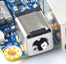
- Notes
- The Power Jack is the only power input port. All power pins at other ports are output.
- How to make T4(1802) start automatically when power is plugged in
- For more details refer to Schematics
4.2 Board Dimension
- For more details refer to the CAD document: NanoPC-T4_1802_Drawing(dxf).zip
5 Get Started
5.1 Essentials You Need
Before starting to use your NanoPC-T4 get the following items ready
- NanoPC-T4
- Type-C cable
- TF Card: Class 10 or Above, minimum 8GB SDHC
- USB to serial adapter(optinal, for debugging or access from PC host)
- A DC 12V/2A power is a must
- HDMI monitor or LCD
- USB keyboard, mouse and possible a USB hub(or a TTL to serial board)
- A host computer running Ubuntu 18.04 64-bit system
5.2 Install OS
5.2.1 Downloads
5.2.1.1 Official image
Visit download link to download official image files (in the "01_Official images" directory).
The table below lists all official images, the word 'XYZ' in image filename meaning:
- sd: Use it when you need to boot the entire OS from the SD card
- eflasher: Use it when you need to flash the OS to eMMC via TF card
- usb: Use it when you need to flash the OS to eMMC via USB
| Icon | Image Filename | Version | Description | Kernel Version |
|---|---|---|---|---|
| |
rk3399-XYZ-android10-YYYYMMDD.img.zip | 10 | Android 10 | 4.4.y |
| |
rk3399-XYZ-android8-YYYYMMDD.img.zip | 8.1 | Android 8.1 | 4.4.y |
| |
rk3399-XYZ-android7-YYYYMMDD.img.zip | 7.1.2 | Android 7.1.2 | 4.4.y |
| |
rk3399-XYZ-debian-bullseye-minimal-4.19-arm64-YYYYMMDD.img.gz | bullseye | Debian 11 Desktop, LXDE desktop, no pre-installed recommended software, supports hardware acceleration | 4.19.y |
| |
rk3399-XYZ-debian-bullseye-desktop-4.19-arm64-YYYYMMDD.img.gz | bullseye | Debian 11 Desktop, LXDE desktop, pre-installed mpv, smplayer and chromium brower, supports hardware acceleration | 4.19.y |
| |
rk3399-XYZ-debian-bookworm-core-4.19-arm64-YYYYMMDD.img.gz | bullseye | Debian 12 Core, No desktop environment, command line only | 4.19.y |
| |
rk3399-XYZ-ubuntu-focal-desktop-4.19-arm64-YYYYMMDD.img.gz | focal | Ubuntu 20.04 Desktop, LXQT desktop, pre-installed mpv, smplayer and chromium brower, supports hardware acceleration | 4.19.y |
| |
rk3399-XYZ-friendlydesktop-bionic-4.4-arm64-YYYYMMDD.img.zip | bionic | 64-bit FriendlyDesktop image file based on Ubuntu desktop 18.04 64bit | 4.4.y |
| |
rk3399-XYZ-friendlycore-focal-4.19-arm64-YYYYMMDD.img.gz | focal | 64-bit FriendlyCore image file(Qt 5.10.0) based on Ubuntu core 20.04 64bit | 4.19.y |
| |
rk3399-XYZ-friendlycore-bionic-4.4-arm64-YYYYMMDD.img.gz | bionic | 64-bit FriendlyCore image file(Qt 5.10.0) based on Ubuntu core 18.04 64bit | 4.4.y |
| |
rk3399-XYZ-lubuntu-desktop-xenial-4.4-armhf-YYYYMMDD.img.zip | xenial | Lubuntu Desktop(with Qt 5.10.0) | 4.4.y |
| |
rk3399-XYZ-ubuntu-noble-core-4.19-arm64-YYYYMMDD.img.gz | noble | 64-bit Ubuntu Lite image file based on Ubuntu core 24.04 64bit | 4.19.y |
| |
rk3399-XYZ-openmediavault-6.1-YYYYMMDD.img.gz | Shaitan | OpenMediaVault NAS system, base on Debian 12 | 6.1.y |
| |
rk3399-XYZ-buildroot-4.19-arm64-YYYYMMDD.img.gz | -- | Buildroot image file with Qt5-wayland (base on Rockchip Linux SDK) | 4.19.y |
| |
rk3399-XYZ-friendlywrt-21.02-YYYYMMDD.img.gz | 21.02 | FriendlyWrt, based on OpenWrt 21.02 | 6.1.y |
| |
rk3399-XYZ-friendlywrt-21.02-docker-YYYYMMDD.img.gz | 21.02 | FriendlyWrt with Docker, based on OpenWrt 21.02 | 6.1.y |
| |
rk3399-XYZ-friendlywrt-23.05-YYYYMMDD.img.gz | 23.05 | FriendlyWrt, based on OpenWrt 23.05 | 6.1.y |
| |
rk3399-XYZ-friendlywrt-23.05-docker-YYYYMMDD.img.gz | 23.05 | FriendlyWrt with Docker, based on OpenWrt 23.05 | 6.1.y |
| Other Image | ||||
| |
Github Actions - FriendlyWrt | 21.02,23.05 | FriendlyWrt | 6.1.y |
| |
rk3399-XYZ-multiple-os-YYYYMMDD-25g.img.gz | - | It contains multiple OS image files, making it convenient for testing different operating systems, this image disables automatic flashing at startup; you will need to manually select the OS to flash. | |
5.2.1.2 Tools (optional)
Visit download link to download tools (in the "05_Tools" directory).
| Filename | Description |
|---|---|
| win32diskimager.rar | This program is designed to write a raw disk image to a removable device or backup a removable device to a raw image file |
| SD Card Formatter | A program (application) that allows easy and quick clear the SD card |
| RKDevTool_Release_v2.84.zip | Rockchip flashing tool, for USB upgrade |
5.2.2 Flashing the OS to the microSD card
Follow the steps below:
- Get an 8G microSD card;
- Visit download linkto download image files (in the "01_Official images/01_SD card images" directory);
- Download the win32diskimager tool (in the "05_Tools" directory), or use your preferred tool;
- Extract the .gz format compressed file to get the .img format image file;
- Run the win32diskimager utility under Windows as administrator. On the utility's main window select your SD card's drive, the wanted image file and click on "write" to start flashing the SD card.
- Take out the SD and insert it to NanoPC-T4's microSD card slot;
- Power on NanoPC-T4 and it will be booted from your TF card, some models may require pressing the Power button to start;
5.2.3 Install OS to eMMC
5.2.3.1 Option 1: Install OS via TF Card
This method firstly boots a mini Linux from a TF card and then automatically runs an EFlasher utility to install the OS to eMMC. You can connect your system to an HDMI monitor and watch its progress.
This is optional. You can watch its progress by observing its LEDs as well:
By default, flashing starts automatically upon power-up, so be sure to back up the data in eMMC. If you don't want it to start automatically, you can use image file with a filename containing the words 'multiple-os' and manually select the OS you want to flash on the interface.
5.2.3.1.1 Flash Official OS to eMMC
Follow the steps below:
- Get an SDHC card with a minimum capacity of 8G
- Visit download linkto download image files (in the "01_Official images/02_SD-to-eMMC images" directory) and win32diskimager tool (in the "05_Tools" directory);
- Extract the .gz format compressed file to get the .img format image file;
- Run the win32diskimager utility under Windows as administrator. On the utility's main window select your SD card's drive, the wanted image file and click on "write" to start flashing the SD card.
- Eject your SD card and insert it to NanoPC-T4’s microSD card slot.
- Turn on NanoPC-T4, it will boot from the SD card and automatically run EFlasher to install the OS to the board’s eMMC.
- After flashing is complete, eject the SD card from NanoPC-T4, NanoPC-T4 will automatically reboot and boot from eMMC.
5.2.3.1.2 Flash third party OS (Image file) to eMMC
- Auto Install (Default Behavior)
1) Download an “eflasher” firmware from network drive(in the "01_Official images/02_SD-to-eMMC images" directory), extract it and install it to a TF card ;
2) Eject and insert the TF card to your PC, after a “FriendlyARM” device shows up(Under Linux, it is a “FriendlyARM” directory), copy the image file ending with .raw or .gz into the directory (Note: if your file is in .img format, please rename it to .raw format).
3) Open the eflasher.conf file on the TF card, set “autoStart=” to the name of your image file, such as:
autoStart=openwrt-rockchip-armv8_nanopi-ext4-sysupgrade.img.gzIn addition to third-party image, official image files which with the '-sd-' word in the filename are also supported, for example: rk3NNN-sd-friendlywrt-21.02-YYYYMMDD.img.gz
4) Eject the TF card, insert the TF card to NanoPC-T4, power it on it will automatically install your firmware. You can watch the installation progress by observing the LEDs’ status.
5.2.3.2 Option 2: Install OS on Web Page
Get a TF card which has been installed with FriendlyWrt, log in FriendlyWrt on the web page, click on “System” ->”eMMC Tools”. Click on “Select file” to select your wanted image file, either an official image (filename containing '-sd-') or a third party image. The file should be a “.gz” or “.img” file.
After a file is selected, click on “Upload and Write” to start installing an OS.
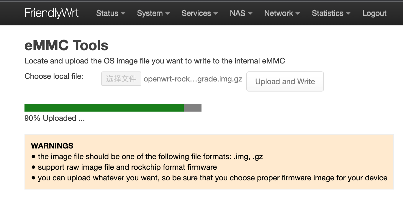
After installation is done, eject the SD card, the system will automatically reboot and load the OS from eMMC. After the OS begins to load, if the system LED is flashing and the network LED is on, it means the the OS has loaded successfully. If the OS is FriendlyWrt, you can click on “Go to Homepage” to enter the homepage.
For official OS, you need select the file with the filename containing '-sd-', for example: rk3NNN-sd-friendlywrt-21.02-YYYYMMDD.img.gz, the compression file only supports the .gz format. If the file is too large, you can compress it into .gz format before uploading.
5.2.3.3 Option 3: Install OS via USB
5.2.3.3.1 Step 1: Install USB Driver and Tools/Utilities
Download a driver file DriverAssitant_v5.12.zip under the “tools” directory from network drive, extract and install it.
Under the same directory, download a utility RKDevTool_Release_v2.84.zip and extract it.
5.2.3.3.2 Step 2: Connect NanoPC-T4 to PC and Enter Installation Mode
Press and hold the “Mask” key, Use a USB cable, connect NanoPC-T4 to a PC,After the status LED has been on for at least 3 seconds, release the Mask key;
5.2.3.3.3 Step 3: Install image to eMMC
A firmware in general is packaged in either of the two options: the first is an whole image (ie, update.img) which is often offered by third party developers, the second is that an image is packaged and placed in multiple partition images. FriendlyElec offers an image in the latter option.
- Option 1: Install whole image (ie, update.img)
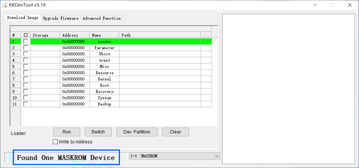
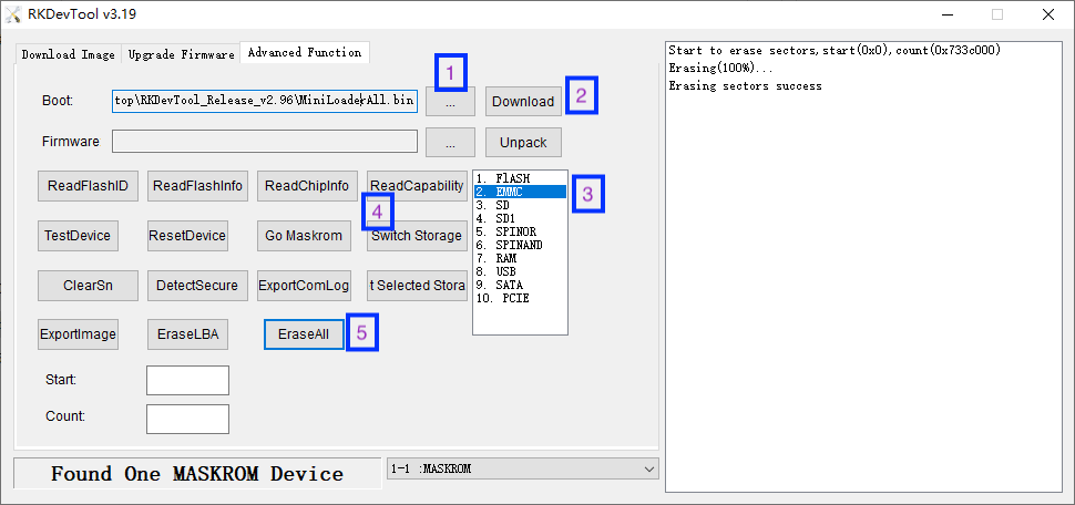
On a PC which has the extracted RKDevTool_Release_v2.84 utility, go to the RKDevTool_Release_v2.84 directory, run the RKDevTool.exe file. If everything works, you will see a “Found a new Maskrom device” message on the utility;
Go to “Upgrade Firmware(升级固件)”, click on “Firmware(固件)”, select your wanted image file, and click on “Upgrade(升级)” to install. After installation is done, your board will reboot automatically and load the system from eMMC;
- Option 2: Install OS that is packaged & placed in multiple partition images
Go to network drive to download your needed package and extract it (in the "01_Official images/03_USB upgrade images).
After it is extracted, you will see some utilities and a configuration file under the directory. double click on RKDevTool.exe, you will see a “Found a new Maskrom device” message on the utility. Click on the “Execute”, wait a moment and it will be installed. After installation is done your system will automatically reboot and load the system from eMMC.
6 Access hardware
6.1 Access Serial Interface
For now only UART4 is available for users:
Serial Interface Serial Device UART0 Used by Bluetooth UART1 Used by Gbps Ethernet UART2 Used by Serial Debug Port UART3 Used by Gbps Ethernet UART4 Available, device name is /dev/ttyS4 (note: this is only applicable for ROM released after 20180618)
7 Work with Debian11 Desktop
7.1 Introduction to Debian11 Desktop
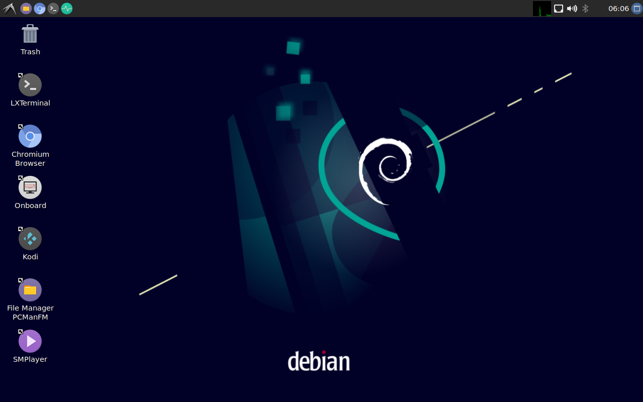
Debian11 Desktop is a light-weighted debian desktop system,it has the following features:
- Uses LXDE as default desktop;
- Mali GPU-based OpenGL support;
- Support Rockhip MPP video hard coding and hard decoding;
- Pre-installed mpv and smplayer, both support 4K video hardware decoding;
- Pre-installed Chromium browser, support vpu/gpu hardware acceleration (video hard decoding limited to h264/mp4 format);
- Compatible with Plex Server and Docker;
7.2 Account & Password
Regular Account:
User Name: pi
Password: pi
Root:
the root user account is disabled by default, you may configure the root password through the 'sudo passwd root' command.
7.3 View IP address
Since the Debian Bullseye hostname is the hardware model by default, you can use the ping command to get the IP address:ping NanoPC-T4
7.4 Connect to Debian via SSH
Run the following commandssh pi@NanoPC-T4
The default password is: pi
7.5 Update Software Packages
$ sudo apt-get update
7.6 Install x11vnc Server on Debian for Remote Access
7.6.1 Install x11vnc server
The following command to install x11vnc server:
sudo apt-get install x11vnc
7.6.2 Set your password
sudo x11vnc -storepasswd /etc/x11vnc.pwd
7.6.3 Setup x11vnc server with systemd auto start up
Create service configuration file:
sudo vi /lib/systemd/system/x11vnc.service
Let’s copy and paste the following configuration into our newly create service file:
[Unit]
Description=Start x11vnc at startup.
Requires=display-manager.service
After=syslog.target network-online.target
Wants=syslog.target network-online.target

[Service]
Type=simple
ExecStart=/usr/bin/x11vnc -display :0 -forever -loop -noxdamage -repeat -rfbauth /etc/x11vnc.pwd -rfbport 5900 -shared -capslock -nomodtweak
ExecStop=/usr/bin/x11vnc -R stop
Restart=on-failure

[Install]
WantedBy=multi-user.target
The following commands to reload the systmd system and to enable and start the x11vnc service:
sudo systemctl daemon-reload
sudo systemctl enable x11vnc.service
sudo systemctl start x11vnc
7.6.4 Testing remote access
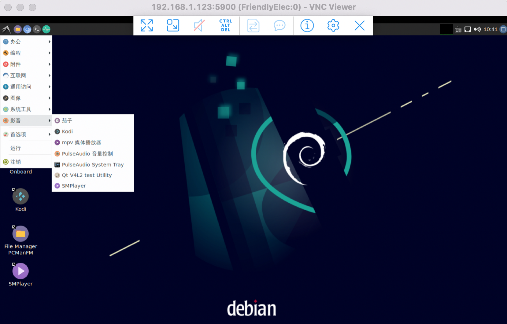
Start the VNC client software, input IP:5900 to connect:
7.7 Install the kernel-header package
sudo dpkg -i /opt/linux-headers-*.deb
try to compile a kernel module:
sudo apt update
sudo apt install git gcc make bc
git clone https://github.com/RinCat/RTL88x2BU-Linux-Driver.git
cd RTL88x2BU-Linux-Driver
make -j$(nproc)
sudo make install
sudo modprobe 88x2bu
7.8 Change time zone
7.8.1 Check the current time zone
timedatectl
7.8.2 List all available time zones
timedatectl list-timezones
7.8.3 Set the time zone (e.g. Shanghai)
sudo timedatectl set-timezone Asia/Shanghai
7.9 Change startup LOGO and Wallpaper
7.9.1 Change startup LOGO
Replace the following two files in the kernel source code directory and recompile the kernel:
kernel/logo.bmp
kernel/logo_kernel.bmp
Or use the script to operate, as shown below:
- Download scripts:
git clone https://github.com/friendlyarm/sd-fuse_rk3399.git -b kernel-4.19 --single-branch
cd sd-fuse_rk3399
- Compile kernel and repackage firmware
convert files/logo.jpg -type truecolor /tmp/logo.bmp
convert files/logo.jpg -type truecolor /tmp/logo_kernel.bmp
sudo LOGO=/tmp/logo.bmp KERNEL_LOGO=/tmp/logo_kernel.bmp ./build-kernel.sh debian-bullseye-desktop-arm64
sudo ./mk-sd-image.sh debian-bullseye-desktop-arm64
sudo ./mk-emmc-image.sh debian-bullseye-desktop-arm64
Note: If your system is not debian-bullseye-desktop-arm64, please specify according to the actual situation
7.9.2 Change Wallpaper
Modify the following configuration file:
/home/pi/.config/pcmanfm/LXDE/desktop-items-0.conf
7.10 Soft Factory Reset
Execute the following command in a terminal:
sudo firstboot && sudo reboot
7.11 Start the program automatically at startup(For example Kodi)
Put the desktop file in the ~/.config/autostart/ directory, for example:
mkdir ~/.config/autostart/
cp /usr/share/applications/kodi.desktop ~/.config/autostart/
7.12 Disable auto-mounting
sudo systemctl mask udisks2
sudo reboot
7.13 Setup Chinese language and Input method
7.13.1 Setup Chinese language
Enter the following command and select 'zh_CN.UTF-8':
sudo dpkg-reconfigure localesAdd environment variables to .bashrc:
echo "export LC_ALL=zh_CN.UTF-8" >> ~/.bashrc
echo "export LANG=zh_CN.UTF-8" >> ~/.bashrc
echo "export LANGUAGE=zh_CN.UTF-8" >> ~/.bashrc
Reboot device:
sudo reboot7.13.2 Installing Chinese input method
Enter the following command to install fcitx and Pinyin input method:
sudo apt update
sudo apt-get install fcitx fcitx-pinyin
sudo apt-get install im-config
sudo apt-get install fcitx-table*
sudo apt-get install fcitx-ui-classic fcitx-ui-light
sudo apt-get install fcitx-frontend-gtk2 fcitx-frontend-gtk3 fcitx-frontend-qt4
sudo apt-get remove --purge scim* ibus*
sudo reboot
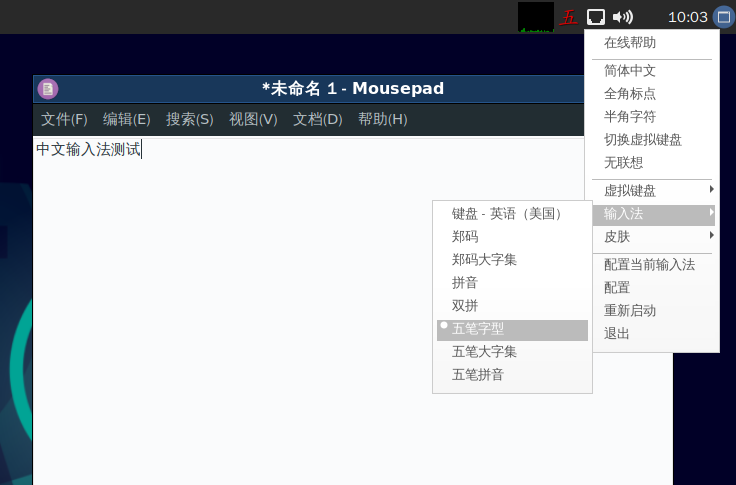
After reboot, press Ctrl+Space to switch between Chinese and English input methods, and the input method icon will appear in the upper right corner, right-click the input method icon in the upper right corner to switch input methods in the pop-up menu, as shown below:
7.14 Installing Plex Multimedia Server
Visit the Plex website: https://www.plex.tv/media-server-downloads/
On the download page, select the category "Plex Media Server", choose "Linux" for the platform and "Ubuntu(16.04+)/Debian(8+) - ARMv8" for the version,
After downloading the deb package, use the dpkg command to install the package:
sudo dpkg -i plexmediaserver_1.31.0.6654-02189b09f_arm64.deb
After installation, login to the Plex server by typing the following URL into your computer browser: http://IP地址:32400/web/
7.15 Install Docker on Debian
Please refer to: How to Install Docker on Debian
7.16 How to test NPU
Please refer to: NPU
7.17 WiFi Connection
7.17.1 Gui
Click on the icon on the top right in the Debian's main window, select your wanted WiFi hotspot and proceed with prompts
7.17.2 Console
Please visit: Use NetworkManager to configure network settings
7.18 Cancel auto-login
Edit file:
sudo vim /etc/lightdm/lightdm.conf
Comment out the following two lines (insert # in front of them):
autologin-user=pi
autologin-user-timeout=0
7.19 Test OpenGL ES
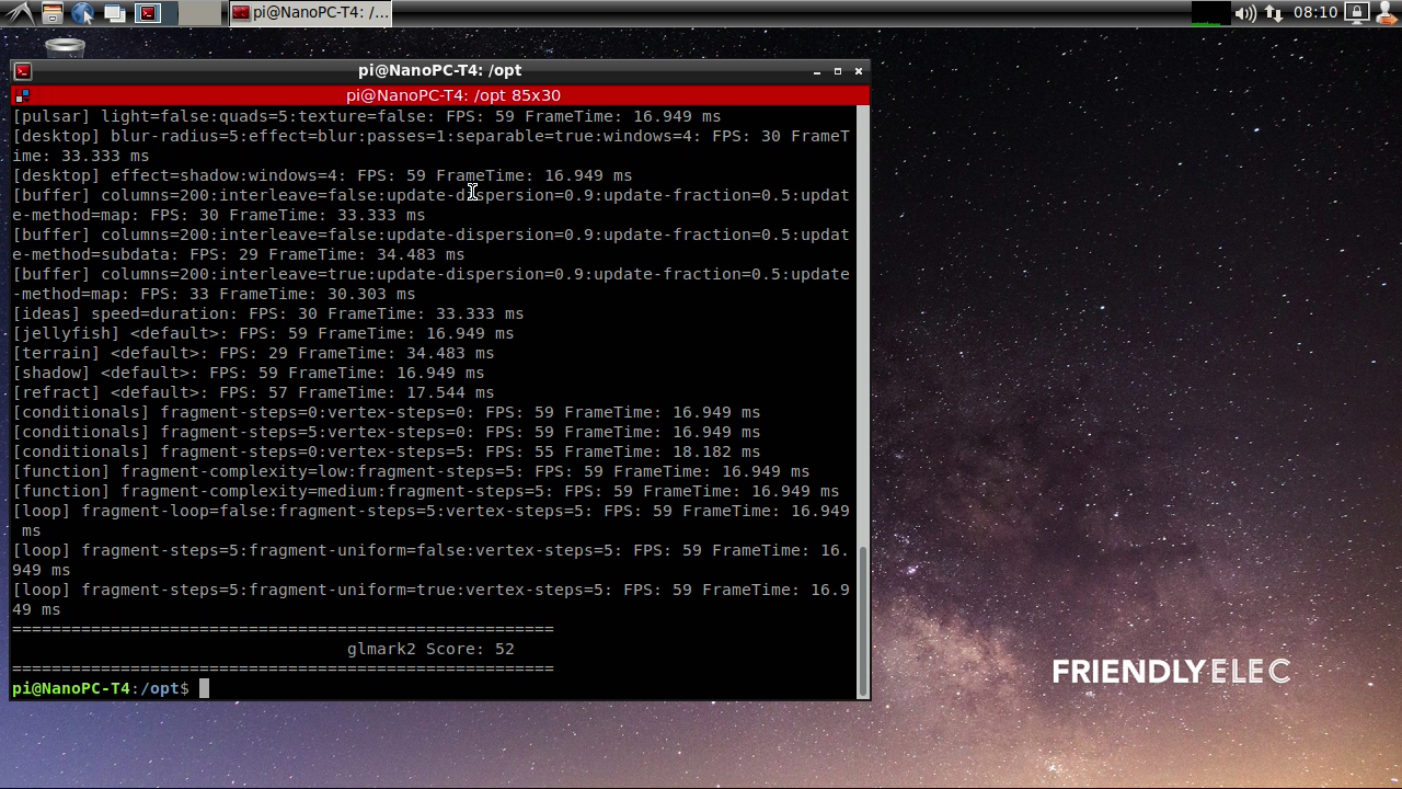
You can test it by clicking on the Terminator icon to start a commandline utility in the System Tools and run the following commands:
glmark2-es2
7.20 HDMI/DP LCD Resolution
Open the system's menu and go to Perferences -> Monitor Settings to customize your settings.
Recommended resolution: 1920x1080@60Hz
7.21 Adjust HDMI overscan
Open the command line terminal and enter the command to operate, Note:
1) You need to login to the desktop;
2) If you are using ssh terminal, please use the same username as the desktop login. The default is pi. You cannot use the root user. you also need to assign the DISPLAY variable:
export DISPLAY=:0.0
7.21.1 Query which resolutions the display supports
xrandr -q7.21.2 Set resolution
For example set to 1920X1080@60Hz:
xrandr --output HDMI-1 --mode 1920x1080 --refresh 60
7.21.3 Adjust the HDMI overscan
For example, the transformation scaling horizontal coordinates by 0.8, vertical coordinates by 1.04 and moving the screen by 35 pixels right and 19 pixels down:
xrandr --output HDMI-1 --transform 0.80,0,-35,0,1.04,-19,0,0,1
7.21.4 Automatic adjustment at boot
Edit ~/.config/autostart/lxrandr-autostart.desktop,Write the full xrandr command to the key at the beginning of "Exec= as shown below:
[Desktop Entry]
Type=Application
Name=LXRandR autostart
Comment=Start xrandr with settings done in LXRandR
Exec=sh -c 'xrandr --output HDMI-1 --mode 1920x1080 --refresh 50 --transform 1.04,0,-35,0,1.05,-30,0,0,1'
OnlyShowIn=LXDE
7.22 Chromium web browser
7.22.1 GPU
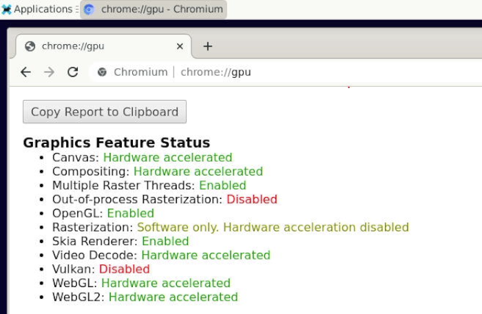
Chromium web browser has enabled hardware acceleration by default, supports WebGL, and can view hardware acceleration details by entering the URL chrome://gpu, as shown below:
7.22.2 VPU
Play a video in the browser, then use fuser on the command line to view the mpp device node to confirm that the vpu interface is being called:
pi@FriendlyElec:~$ fuser /dev/mpp_service
/dev/mpp_service:     3258
If there is no content output from the fuser command, it means software decoding.
7.23 Test hardware encoding
mpi_enc_test -w 1920 -h 1080 -t 7 -f 0 -o test.h264 -n 300
export XDG_RUNTIME_DIR=/run/user/0
ffplay test.h264
7.23.1 Check Supported Hardware Decoding Formats
Enter about://gpu in your browser's address bar and scroll to the bottom of the page to view the "Video Acceleration Information" table.
After playing a video, enter about://media-internals in your browser's address bar to check if hardware decoding was enabled for the most recent playback.
8 Work with Debian10 Desktop
- Refer to:
9 Work with FriendlyDesktop
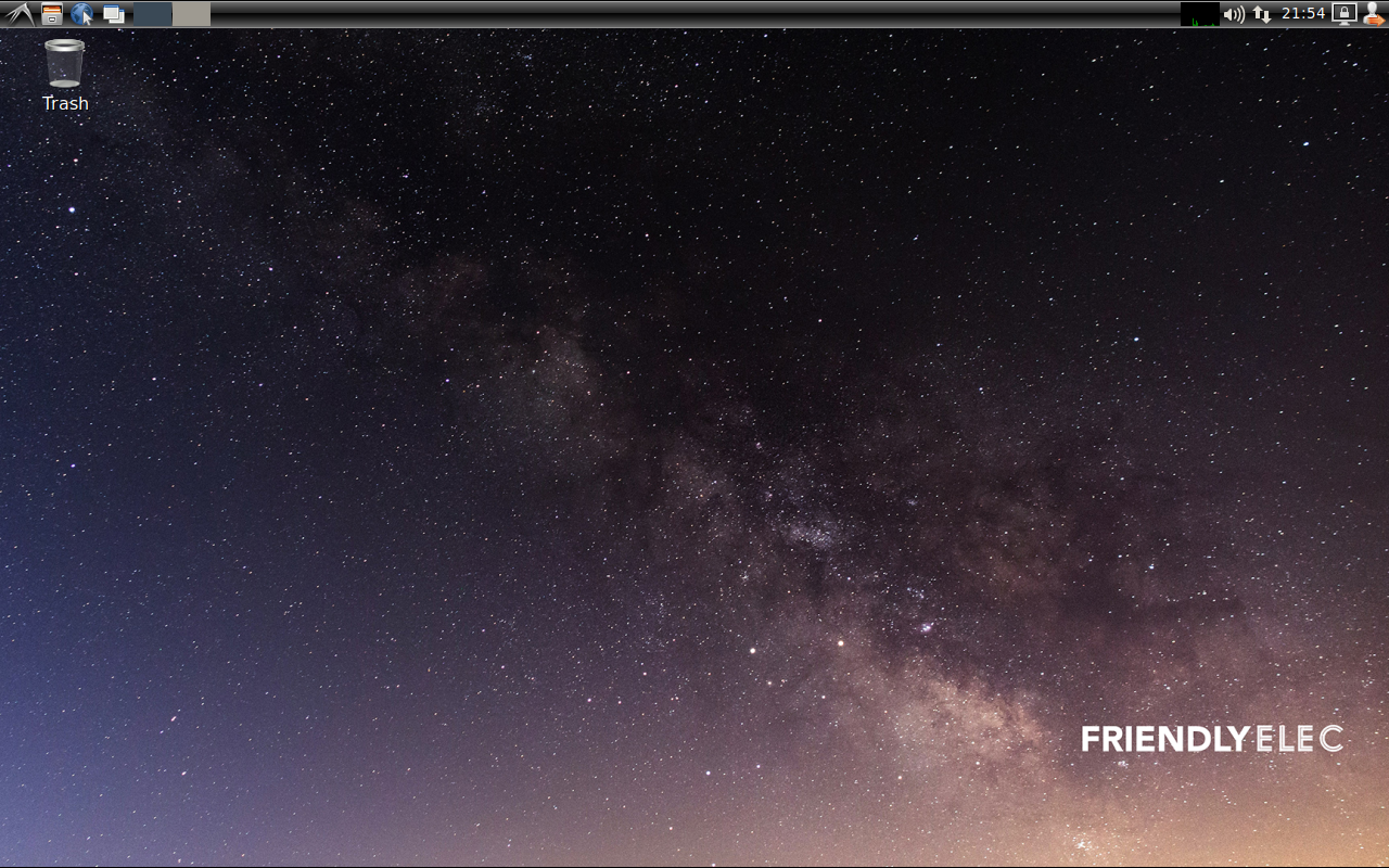
FriendlyDesktop is a light-weighted Ubuntu desktop system. It is based on LXDE and has the following features:
Latest Version - Based on Ubuntu 18.04 64
Various Development Utilities - It is compatible with FriendlyCore and has integrated an optimized Qt5.10, QtCreator and Arduino IDE.
Light-weighted - it consumes relatively less CPU resources than a common desktop system. When a system's RAM is sufficient it can achieve much better performance.
Less Power Consumption - it consumes relatively less power or resources than a common desktop system to achieve the same performance.
Compact and Neat - its desktop is based on GTK+ 2 and it supports multiple languages.
Easy to Use - its GUI looks similar to MS Windows'.
Customizable - Users can customize LXDE's GUI.
Compatible - it is compatible with freedesktop.org.
FriendlyELEC has optimized support for Mali GPU and VPU in FriendlyDesktop for RK3399 and integrated drivers for X.org. FriendlyDesktop supports Hardware Cursor, OpenGL graphic acceleration, 4K video playing with hardware decoding.
9.1 Account & Password
Regular Account:
   User Name: pi
   Password: pi
Root:
   User Name: root
   Password: fa
9.2 WiFi Connection
Click on the icon on the top right in the FriendlyDesktop's main window, select your wanted WiFi hotspot and proceed with prompts
9.3 HDMI/DP LCD Resolution
Open the system's menu and go to Perferences -> Monitor Settings to customize your settings.
Recommended resolution: 1920x1080@60Hz
9.4 Adjust HDMI overscan
Open the command line terminal and enter the command to operate, Note:
1) You need to login to the desktop;
2) If you are using ssh terminal, please use the same username as the desktop login. The default is pi. You cannot use the root user. you also need to assign the DISPLAY variable:
export DISPLAY=:0.0
9.4.1 Query which resolutions the display supports
xrandr -q9.4.2 Set resolution
For example set to 1920X1080@60Hz:
xrandr --output HDMI-1 --mode 1920x1080 --refresh 60
9.4.3 Adjust the HDMI overscan
For example, the transformation scaling horizontal coordinates by 0.8, vertical coordinates by 1.04 and moving the screen by 35 pixels right and 19 pixels down:
xrandr --output HDMI-1 --transform 0.80,0,-35,0,1.04,-19,0,0,1
9.4.4 Automatic adjustment at boot
Edit ~/.config/autostart/lxrandr-autostart.desktop,Write the full xrandr command to the key at the beginning of "Exec= as shown below:
[Desktop Entry]
Type=Application
Name=LXRandR autostart
Comment=Start xrandr with settings done in LXRandR
Exec=sh -c 'xrandr --output HDMI-1 --mode 1920x1080 --refresh 50 --transform 1.04,0,-35,0,1.05,-30,0,0,1'
OnlyShowIn=LXDE
9.5 eDP LCD Display Rotation
If you want to rotate an eDP LCD's display you can do it by commanding "xrotate.sh" to rotate its display to 90/180/270 degrees. You can rotate display clockwise by 90 degrees by running the following command as root. This command calls lightdm to make your change effective immediately:
sudo xrotate.sh -m CW -r
For more details about its options you can run "xrotate -h".
Note: this command doesn't support HDMI display's rotation. If you want to rorate an HDMI's display you need to refer to X11's tech documents and make changes in "/etc/X11/xorg.conf".
Note: when you play a video with hardware decoding your player's display window doesn't rotate with your LCD's display
9.6 Test OpenGL ES
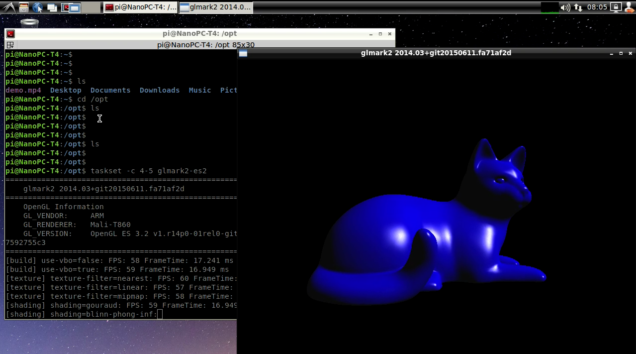
You can test it by clicking on the Terminator icon to start a commandline utility in the System Tools and run the following commands:
taskset -c 4-5 glmark2-es2
9.7 4K Video Playing
9.7.1 Play with Qt Player with Hardware Decoding
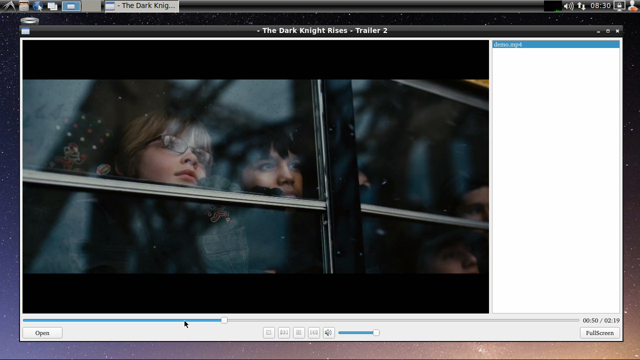
FriendlyDesktop has integrated a Qt5-VideoPlayer utility. This utility has support for Rockchip's gstreamer plug-in and supports 4K video playing with hardware decoding. You can start it by following the steps below:
On FriendlyDesktop's main window open "Sound & Video" and click on "Qt5-VideoPlayer".
On the player's main window click on the bottom left's "Open" button to load a video file and double-click on its name on the file list to start video playing. Here is how it looks like. You can set the display window to full screen and adjust the volume:
Qt5-VideoPlayer source code: https://github.com/friendlyarm/rk-player-qt
9.7.2 Play with Linux Command
You can play it by running the following command in a commandline utility:
gst-player.sh
By default its voice will be output to audio jack. You can locate this script by commanding "which gst-player.sh". You can customize its behavior by making changes in this script.
9.8 Work with USB Camera
Insert the USB camera (such as Logitech C270/C920) into the development board. Double click the "USB Camera" icon on desktop will pop up the luvcview gui (need to use the 2019/05/11+ version firmware).
the luvcview tool is an open source software that you can compile yourself:
git clone https://github.com/ksv1986/luvcview
cd luvcview
make
View the usage of luvcview:
./luvcview -h
Parameter Description:
luvcview version 0.2.1
Usage: uvcview [-h -d -g -f -s -i -c -o -C -S -L -l -r]
-h print this message
-d /dev/videoX use videoX device
-g use read method for grab instead mmap
-w disable SDL hardware accel.
-f video format default jpg others options are yuv jpg
-i fps use specified frame interval
-s widthxheight use specified input size
-c enable raw frame capturing for the first frame
-C enable raw frame stream capturing from the start
-S enable raw stream capturing from the start
-o avifile create avifile, default video.avi
-L query valid video formats
-l query valid controls and settings
-r read and set control settings from luvcview.cfg
To preview USB camera (640x360@30fps), you can use the following command:
./luvcview -d /dev/video8 -i 30 -s 640x360
As you can see from the output of luvcview, hardware acceleration has been turned on:
pi@NanoPC-T4:/etc/xrdp$ luvcview -d /dev/video8 -i 30 -s 640x360
luvcview version 0.2.1
 interval: 30 fps
Hardware acceleration available
video /dev/video8
9.9 File Transfer with Bluetooth
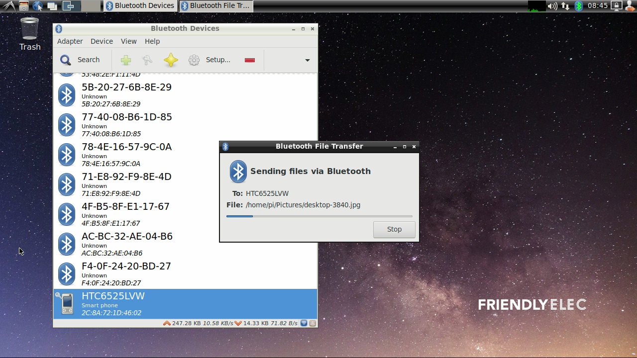
Click on the "Preferences" in the main window's menu to start Bluetooth Manager and click on "Search" to search surrounding Bluetooth devices. Click on your wanted device, pair the device with your board and you will be able to do file transfer, here is how it looks like:
9.10 Install OpenCV
OpenCV has been pre-installed in FriendlyCore/FriendlyDesktop (Version after 201905) and does not require manual installation.
Please refre this link: https://github.com/friendlyarm/install-opencv-on-friendlycore/blob/rk3399/README.md
9.11 Develop Qt Applications
FriendlyDesktop has a Qt 5.10.0 which supports RK3399's OpenGL ES and Gstreamer 1.0 hardware acceleration and a QtCreator IDE which is ready and can be used to compile and run applications. Here is how it looks like:
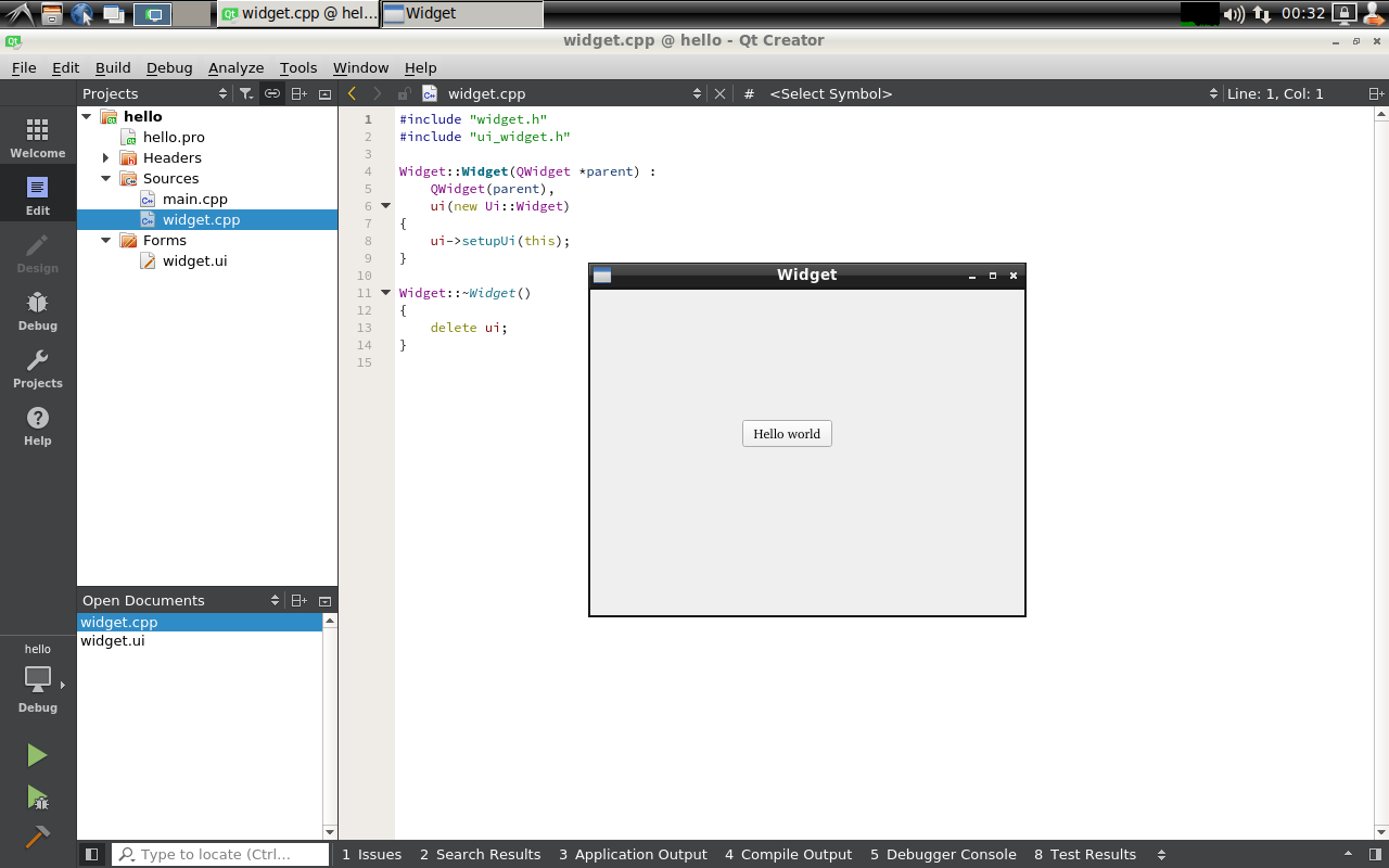
When running the Qt app, you need to specify the platform parameter to xcb as follows:
./HelloQt --platform xcb
9.12 WiringPi and Python Wrapper
9.13 Switch audio default output device
9.13.1 View the current default output device
On the terminal of the non-root user, enter the following command:
pactl info -vvvThe information displayed contains the following, indicating that the current audio output is directed to the headset:
Default Sink: alsa_output.platform-rt5651-sound.stereo-fallback
The information displayed contains the following, indicating that the current audio output is to HDMI:
Default Sink: alsa_output.platform-hdmi-sound.stereo-fallback
9.13.2 Set headphone jack as the default output device
On the terminal of the non-root user, enter the following command:
pactl set-default-sink alsa_output.platform-rt5651-sound.stereo-fallback
Set default volume to 20%:
pactl -- set-sink-volume alsa_output.platform-rt5651-sound.stereo-fallback 20%
9.13.3 Set hdmi as the default output device
On the terminal of the non-root user, enter the following command:
pactl set-default-sink alsa_output.platform-hdmi-sound.stereo-fallback
9.13.4 View settings have taken effect
cat /var/lib/pulse/*-default-sink
9.13.5 Temporary switching during playback
This method is only valid for the current playback process:
Open the menu "Sound & Video" -> "PulseAudio Volume Control", click the "Built-in Audio Stereo" button on the interface to switch between different output devices, such as switching between HDMI and headphone jack.
9.14 Play RTSP video stream (or IP Camera)
Open a command line terminal and enter the following command:
gst-launch-1.0 rtspsrc location="rtsp://admin:12345@192.168.1.120:554/live/main" ! rtph264depay ! decodebin ! rkximagesink
Change the address after rtsp:// to the real address.
9.15 Chromium web browser
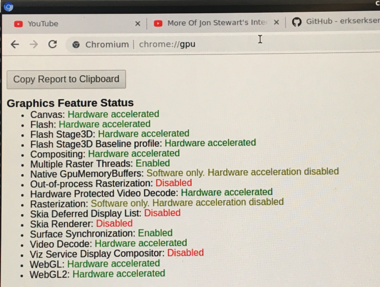
Chromium web browser has enabled hardware acceleration by default, supports WebGL, and can view hardware acceleration details by entering the URL chrome://gpu, as shown below:
The screen saver configuration file is /etc/xdg/autostart/xset_command.desktop. The default factory settings are that the screen saver and DPMS are both closed. You can change the configuration by modifying this file.
9.17 Install Scratch
enter the following command:
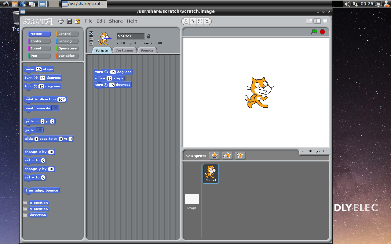
sudo apt-get install scratch:arm64
9.18 Install Arduino IDE
enter the following command:
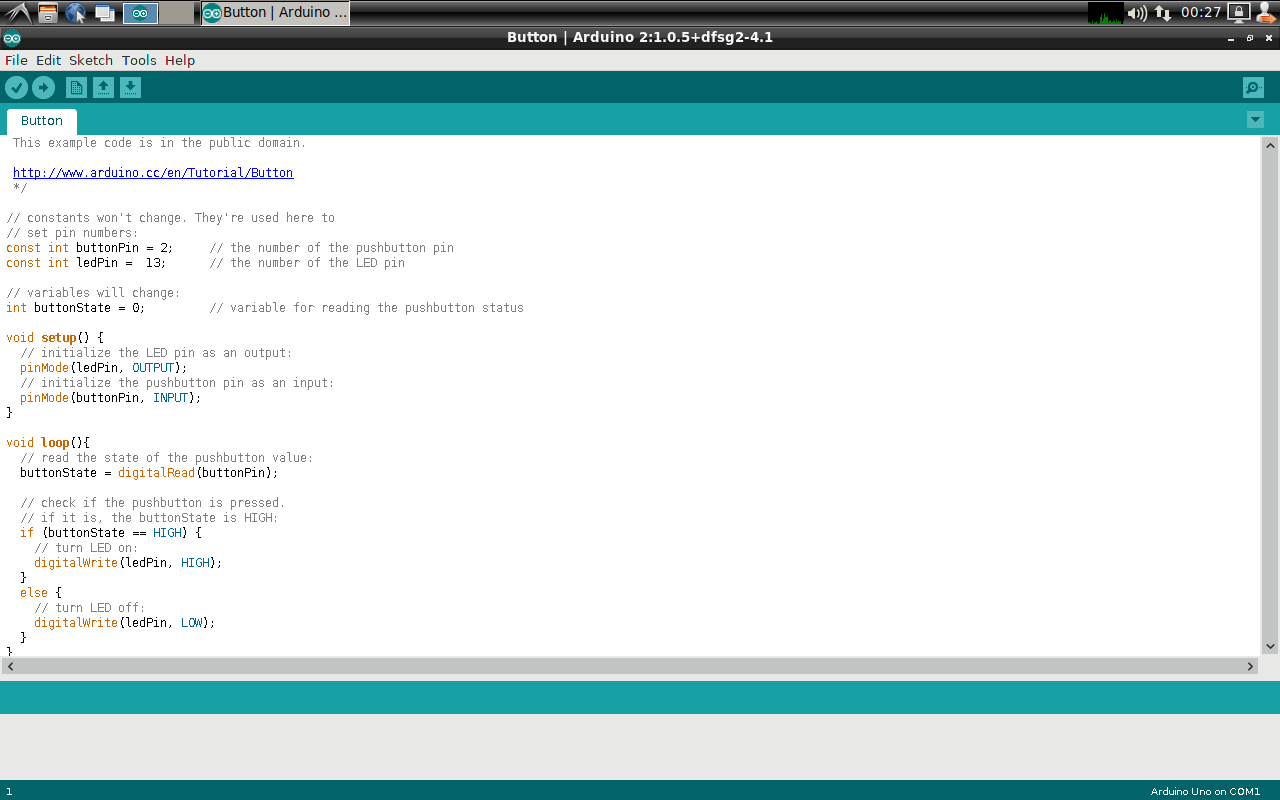
sudo apt-get install arduino:arm64
9.19 Start the program automatically at startup
Put the desktop file in the ~/.config/autostart/ directory, for example:
cp /usr/share/applications/org.qt-project.qtcreator.desktop ~/.config/autostart/
9.20 Login to the desktop as the root user
Edit the /root/.profile file:
sudo vim /root/.profile
Replace with the following:
if [ -n "$BASH_VERSION" ]; then
    if [ -f "$HOME/.bashrc" ]; then
	. "$HOME/.bashrc"
    fi
fi
if [ -d "$HOME/bin" ] ; then
    PATH="$HOME/bin:$PATH"
fi
Run the following command to modify the lightdm configuration file and change the automatically logged-in user name to root:
sudo sed -i 's/autologin-user=pi/autologin-user=root/g' /usr/share/lightdm/lightdm.conf.d/20-defaultsession.conf
Run the reboot command to restart:
sudo rebootIf you want to log in, the desktop icons and configuration are the same as the pi user, you can copy the relevant directory from the /home/pi directory:
sudo rm -rf /root/Desktop /root/Pictures /root/.config
sudo cp -af /home/pi/Desktop /home/pi/Pictures /home/pi/.config /root/
sudo chown root:root /root/Desktop /root/Pictures /root/.config
9.21 Using NVME SSD on FriendlyDesktop
Please see this article: How to Initialize and Format New SSD And HDD
9.22 How to setup WiFiAP on FriendlyDesktop
Please see this article: Template:Linux-Create-WiFiAP
10 Work with FriendlyCore
10.1 Introduction
FriendlyCore is a Ubuntu core based OS which doesn't have X Desktop. Its current version is 18.04
FriendlyCore targets enterprise users and is customized for industrial applications. FriendlyCore and Ubuntu base target different users. FriendlyCore has both a commandline utility and a two GUI utilities:
1)Qt 5.10.0 cuustomized for ROCKCHIP3399. It supports GPU and VPU acceleration and has modules like: QtQuick/QtWebEngine/QtMultimedia/WebGL and three display plug-ins:KMS, EGLFS and XCB;
2) Xorg system. It can run X11 applications and supports hardware acceleration;
FriendlyCore for RK3399 has the following features:
- supports FriendlyElec's 7"LCD with capacitive touch - HD702. If a board is connected to both an LCD and an HDMI monitor the LCD and the HDMI monitor can be set to display either differently or the same;
- supports Gstreamer 1.0 multi-media framework;
- supports hard encoding video playing with either commandline utility or Qt player;
- supports Qt5 WebGL;
- supports Qt5 VNC and runs a Qt application as a VNC Server allowing remote control;
- supports bluetooth. It has preinstalled bluez packages;
10.2 System Login
- If your board is connected to an HDMI monitor you need to use a USB mouse and keyboard.
- If you want to do kernel development you need to use a serial communication board, ie a PSU-ONECOM board, which will
You can use a USB to Serial on NanoPC-T4: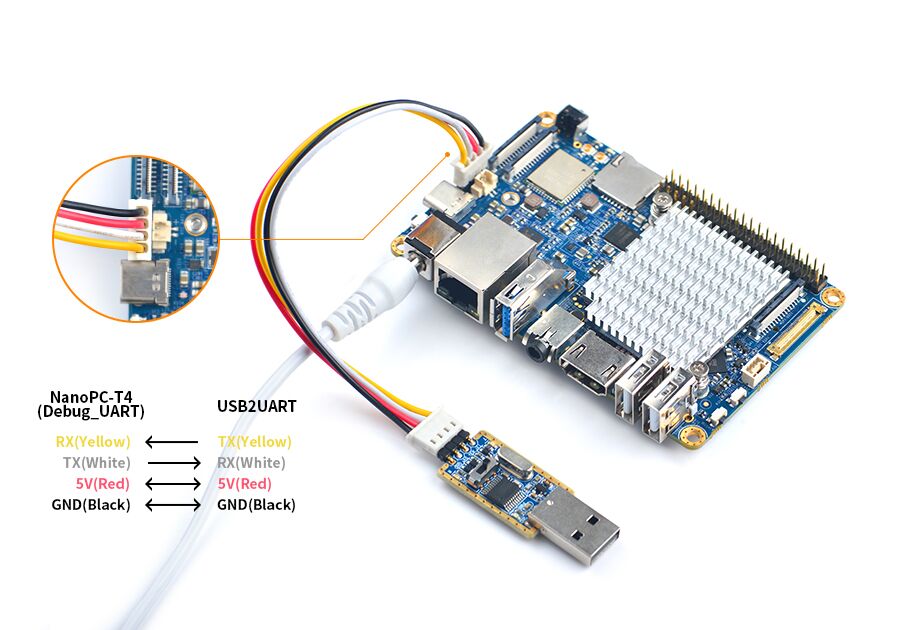
- FriendlyCore User Accounts:
Non-root User:
   User Name: pi
   Password: pi
Root:
   User Name: root
   Password: fa
The system is automatically logged in as "pi". You can do "sudo npi-config" to disable auto login.
- Update packages
$ sudo apt-get update
10.3 Configure System with npi-config
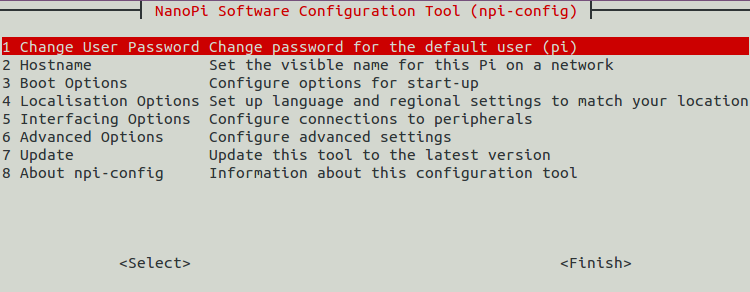
The npi-config is a commandline utility which can be used to initialize system configurations such as user password, system language, time zone, Hostname, SSH switch , Auto login and etc. Type the following command to run this utility.
$ sudo npi-config
Here is how npi-config's GUI looks like:
10.4 Develop Qt Application
The Qt 5.10.0 FriendlyELEC ported for RK3399 supports the following plug-ins:KMS, EGLFS and XCB. All these three plug-ins support OpenGL ES and GPU hardware acceleration but in different ways:
- KMS - it calls Linux kernel's DRM interface to display
- EGLFS - it calls OpenGL ES interface to display
- XCB - it runs on X11 server and is integrated in X11 windows system
Three plug-ins support different Qt features and here is a table:
Plug-in OpenGL ES QtWebEngine QtMultimedia Video Playing with Hardware Decoding Different Display KMS Yes No Yes No Yes EGLFS Yes No Yes No No XCB Yes Yes Yes Yes Yes
We recommend to use KMS or XCB.
FriendlyCore has four scripts for setting Qt environmental variables for users and here is a table:
Script Comment /usr/bin/setqt5env-kms set kms' environmental variables /usr/bin/setqt5env-eglfs set eglfs' environmental variables /usr/bin/setqt5env-xcb set xcb's environmental variables /usr/bin/setqt5env-nogui set environmental variables for a system without a Qt GUI
For instance, if you want to use KMS to display you can run the following commands:
. setqt5env-kms
./apps
(Note:there is a space between '.' and 's')
10.4.1 Setup Qt Development Envronment
FriendlyELEC developed two methods for RK3399 to cross-compile a Qt program:
- 1:Use Docker. For more details you can refer to github :http://github.com/friendlyarm/friendlyelec-ubuntu18-docker
- 2:Setup a local cross-compiler. You need to run a Ubuntu 18.04 64-bit OS and you can refer to :How to Build and Install Qt Application for FriendlyELEC Boards/zh
10.4.2 Qt Demo
FriendlyCore has several Qt demo programs:
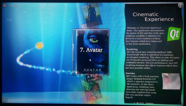
- Qt QML: CinematicExperience
CinematicExperience is a utility for selecting a video file and it is developed with Qt QML.
This demo uses Qt QML's various features and runs very smoothly on RK3399. This performance is achieved by hardware and software optimization.
You can start it in a commandline utility by running the following commands:
cd /opt/Qt5_CinematicExperience
./run.sh
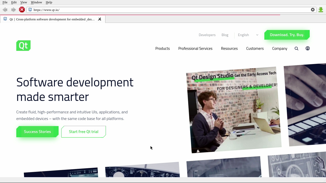
- QQt WebEngine: web browser
Qt WebEngine uses Chromium and supports HTML5.
You can start it by running the following commands:
cd /opt/qt5-brower
./run.sh
Note:Qt WebEngine depends on the Xcb plug-in.
- Qt Different Display
This demo shows that when a board is connected to an HDMI monitor and an eDP LCD these two devices display differently. You can start it by running the following commands:
cd /opt/qt5-multi-screen-demo
./run.sh
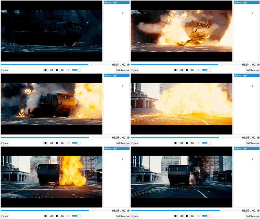
- Qt Multimedia: qt5-player with hard decoding
The qt5-player works with Rockchip's gstreamer plug-in and supports 4K video playing. Since Rockchip's plug-in only supports output images to an X11 window the qt5-player needs to use XCB for display.
You can start the demo by running the following commands:
cd /opt/qt5-player
./run.sh
Here is what it looks like. You can set it to display in full-screen and adjust the voice's volume:
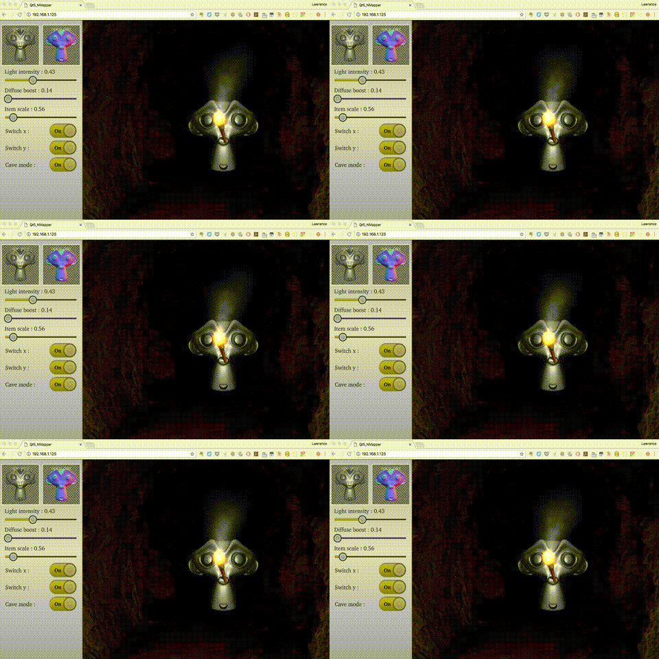
- Qt WebGL demo: nmapper
Qt WebGL allows you to remotely access a Qt program running on your board.
Before you run the demo you need to connect your board to the internet and run the following commands:
cd /opt/qt5-nmapper
./run-with-webgl.sh
You can open a browser on another device, type the IP address of your board on the browser's address bar, enter and you will be able to see a Qt GUI. Here is what it looks like:
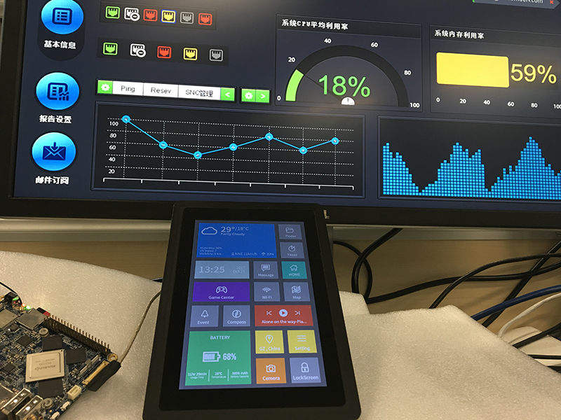
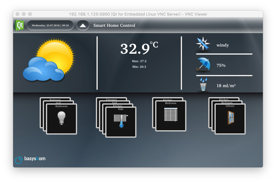
- Qt VNC demo: Smart home applicance GUI
Qt VNC allows you to run a program as a VNC Server on your board and you can access the program from a VNC client on another device. This program can be developed with either QtWidgets or QML.
You can start it by running the following commands:
cd /opt/qt5-smarthome
./run-with-vnc.sh
Start a VNC viewer on a smart phone or mobile device and type your board's IP address and port number 5900. For instance if your board's IP address is 192.168.1.100 you can type "192.168.1.100:5900", enter and you will see the following GUI:
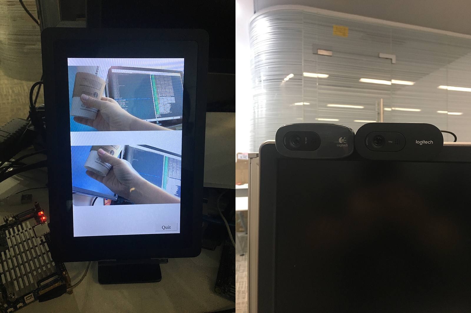
10.4.3 Play with Dual Cameras under Qt
This sample shows how to connect dual cameras to the board and play with them. Before run the sample make sure you connect dual cameras and an LCD to your board. In general popular UVC cameras should work however we suggest users use the following modules which we have tested:
Index Model 1 Logitech C270 2 Logitech C270i 3 Logitech C922 Pro
Run the following commands:
cd /opt/dual-camera
./run.sh
Here is what you expect to observe:
10.5 Setup Program to AutoRun
You can setup a program to autorun on system boot with npi-config:
sudo npi-configGo to Boot Options -> Autologin -> Qt/Embedded, select Enable and reboot.
10.6 Extend TF Card's Section
When FriendlyCore is loaded the TF card's section will be automatically extended.You can check the section's size by running the following command:
$ df -h
10.7 Transfer files using Bluetooth
Take the example of transferring files to the mobile phone. First, set your mobile phone Bluetooth to detectable status, then execute the following command to start Bluetooth search.:
hcitool scan
Search results look like:
Scanning ...
    2C:8A:72:1D:46:02   HTC6525LVW
This means that a mobile phone named HTC6525LVW is searched. We write down the MAC address in front of the phone name, and then use the sdptool command to view the Bluetooth service supported by the phone:
sdptool browser 2C:8A:72:1D:46:02
Note: Please replace the MAC address in the above command with the actual Bluetooth MAC address of the mobile phone.
This command will detail the protocols supported by Bluetooth for mobile phones. What we need to care about is a file transfer service called OBEX Object Push. Take the HTC6525LVW mobile phone as an example. The results are as follows:
Service Name: OBEX Object Push
Service RecHandle: 0x1000b
Service Class ID List:
  "OBEX Object Push" (0x1105)
Protocol Descriptor List:
  "L2CAP" (0x0100)
  "RFCOMM" (0x0003)
    Channel: 12
  "OBEX" (0x0008)
Profile Descriptor List:
  "OBEX Object Push" (0x1105)
    Version: 0x0100
As can be seen from the above information, the channel used by the OBEX Object Push service of this mobile phone is 12, we need to pass it to the obexftp command, and finally the command to initiate the file transfer request is as follows:
obexftp --nopath --noconn --uuid none --bluetooth -b 2C:8A:72:1D:46:02 -B 12 -put example.jpg
Note: Please replace the MAC address, channel and file name in the above command with the actual one.
After executing the above commands, please pay attention to the screen of the mobile phone. The mobile phone will pop up a prompt for pairing and receiving files. After confirming, the file transfer will start.
Bluetooth FAQ:
1) Bluetooth device not found on the development board, try to open Bluetooth with the following command:
rfkill unblock 02) Prompt can not find the relevant command, you can try to install related software with the following command:
apt-get install bluetooth bluez obexftp openobex-apps python-gobject ussp-push10.8 WiFi
For either an SD WiFi or a USB WiFi you can connect it to your board in the same way. The APXX series WiFi chips are SD WiFi chips. By default FriendlyElec's system supports most popular USB WiFi modules. Here is a list of the USB WiFi modules we tested:
Index Model 1 RTL8188CUS/8188EU 802.11n WLAN Adapter 2 RT2070 Wireless Adapter 3 RT2870/RT3070 Wireless Adapter 4 RTL8192CU Wireless Adapter 5 mi WiFi mt7601 6 5G USB WiFi RTL8821CU 7 5G USB WiFi RTL8812AU
You can use the NetworkManager utility to manage network. You can run "nmcli" in the commandline utility to start it. Here are the commands to start a WiFi connection:
- Change to root
$ su root
- Check device list
$ nmcli devNote: if the status of a device is "unmanaged" it means that device cannot be accessed by NetworkManager. To make it accessed you need to clear the settings under "/etc/network/interfaces" and reboot your system.
- Start WiFi
$ nmcli r wifi on- Scan Surrounding WiFi Sources
$ nmcli dev wifi- Connect to a WiFi Source
$ nmcli dev wifi connect "SSID" password "PASSWORD" ifname wlan0
The "SSID" and "PASSWORD" need to be replaced with your actual SSID and password.If you have multiple WiFi devices you need to specify the one you want to connect to a WiFi source with iface
If a connection succeeds it will be automatically setup on next system reboot.
For more details about NetworkManager refer to this link: Use NetworkManager to configure network settings
If your USB WiFi module doesn't work most likely your system doesn't have its driver. For a Debian system you can get a driver from Debian-WiFi and install it on your system. For a Ubuntu system you can install a driver by running the following commands:
$ apt-get install linux-firmware
In general all WiFi drivers are located at the "/lib/firmware" directory.
10.9 Ethernet Connection
If a board is connected to a network via Ethernet before it is powered on it will automatically obtain an IP with DHCP activated after it is powered up. If you want to set up a static IP refer to: Use NetworkManager to configure network settings。
10.10 WiringPi and Python Wrapper
10.11 Custom welcome message
The welcome message is printed from the script in this directory:
/etc/update-motd.d/
For example, to change the FriendlyELEC LOGO, you can change the file /etc/update-motd.d/10-header. For example, to change the LOGO to HELLO, you can change the following line:
TERM=linux toilet -f standard -F metal $BOARD_VENDOR
To:
TERM=linux toilet -f standard -F metal HELLO
10.12 Modify timezone
For exampe, change to Shanghai timezone:
sudo rm /etc/localtime
sudo ln -ls /usr/share/zoneinfo/Asia/Shanghai /etc/localtime
10.13 Select the system default audio device
You can set the system default audio device by following the steps below.
Use the following command to view all the sound card devices in the system (Note: different development boards will have different results):
pi@NanoPi:~$ aplay -l
**** List of PLAYBACK Hardware Devices ****
card 0: realtekrt5651co [realtek,rt5651-codec], device 0: ff880000.i2s-rt5651-aif1 rt5651-aif1-0 []
  Subdevices: 1/1
  Subdevice #0: subdevice #0
card 1: rockchiphdmi [rockchip,hdmi], device 0: ff8a0000.i2s-i2s-hifi i2s-hifi-0 []
  Subdevices: 1/1
  Subdevice #0: subdevice #0
card 2: ROCKCHIPSPDIF [ROCKCHIP,SPDIF], device 0: ff870000.spdif-dit-hifi dit-hifi-0 []
  Subdevices: 1/1
  Subdevice #0: subdevice #0
As you can see, the following sound card devices are available on the hardware:
Sound card device Sound card number Description realtekrt5651co 0 Realtek sound card's default output interface (through 3.5mm jack interface) rockchiphdmi 1 HDMI ROCKCHIPSPDIF 2 SPDIF (Note: temporarily unavailable, because the hardware is not exported)...
To configure the audio output to the 3.5mm jack, modify the configuration file /etc/asound.conf and modify it to the following:
defaults.pcm.card 0
defaults.pcm.device 0
To configure to output audio to HDMI, change the defaults.pcm.card above to 1.
Note that some boards do not have a Realtek sound card (no 3.5mm jack interface), so the card number of the HDMI device will be 0, so the configuration should be based on the result of the aplay -l command.
10.14 Change the behavior of the PWM fan
By default, the speed of the fan is dynamically adjusted according to the CPU temperature. If you need to let the fan run, you can modify the script /usr/bin/start-rk3399-pwm-fan.sh to the following:
#!/bin/bash

echo 0 > /sys/class/pwm/pwmchip1/export
sleep 1
echo 0 > /sys/class/pwm/pwmchip1/pwm0/enable
echo 50000 > /sys/class/pwm/pwmchip1/pwm0/period
echo 1 > /sys/class/pwm/pwmchip1/pwm0/enable
echo 45000 > /sys/class/pwm/pwmchip1/pwm0/duty_cycle
10.15 Run the X11 application
FriendlyCore system built-in lightweight Xorg,although there is no window manager, you can still run a single X-Windows application,For example, the program to run is ~/YourX11App,use the following command:
. /usr/bin/setqt5env-xcb
startx ~/YourX11App -geometry 1280x800
Note that there is a space between "." and /usr/bin/setqt5env-xcb. In addition, the resolution after -geometry should be changed to the actual resolution of your screen.
10.16 Mpv hardware decoding video player
FriendlyCore comes pre-installed with the ffmpeg-based command line video player mpv, which also includes libmpv.
The mpv player supports Rockchip MPP video decoder, so it supports 4K hardware decoding. There are many parameters of mpv. In order to simplify the use, we provide a script start-mpv. After simplification, there is only one parameter: video file name, as follows:
start-mpv /home/pi/demo.mp4
It should be noted that the pi user needs to log in during playback, because there are no mpv related settings in other users' directories. Of course, you can copy one from the pi user directory. The mpv settings file is stored in the following path:
/home/pi/.config/mpv/mpv.conf
The contents of the mpv.conf file are as follows:
vo=gpu
gpu-context=drm
hwdec=rkmpp
demuxer-max-bytes=41943040
demuxer-max-back-bytes=41943040
drm-osd-plane-id=1
drm-video-plane-id=0
audio-device=alsa/default:CARD=rockchiphdmi
These will be passed as parameters to mpv. When the value of hwdec is rkmpp, it means using hardware decoding, audio-device is used to specify the audio output device, and the default output is to HDMI. You can use the following command to query which audio devices are in the system:
mpv --audio-device=help
Another important parameter is drm-osd-size. When playing video in full screen, drm-osd-size is specified as the resolution of the screen. This parameter is automatically obtained by start-mpv and passed to mpv, start-mpv script will do one more important thing. It needs to ensure that the libmali library in the system uses the correct version, because mpv renders the image through gbm, so libmali.so needs to use this version: libmali-midgard-t86x -r14p0-gbm.so, which means that this version of mpv can only be used under FriendlyCore, can not be used under X11 Desktop.
Mpv official use guide:https://github.com/mpv-player/mpv/wiki
10.17 Change startup LOGO
Replace the following two files in the kernel source code directory and recompile the kernel:
kernel/logo.bmp
kernel/logo_kernel.bmp
Or use the script to operate, as shown below:
git clone https://github.com/friendlyarm/sd-fuse_rk3399
cd sd-fuse_rk3399
convert files/logo.jpg -type truecolor /tmp/logo.bmp
convert files/logo.jpg -type truecolor /tmp/logo_kernel.bmp
LOGO=/tmp/logo.bmp KERNEL_LOGO=/tmp/logo_kernel.bmp ./build-kernel.sh eflasher
LOGO=/tmp/logo.bmp KERNEL_LOGO=/tmp/logo_kernel.bmp ./build-kernel.sh friendlydesktop-arm64
./mk-emmc-image.sh friendlydesktop-arm64
11 Features applicable to FriendlyDesktop and FriendlyCore
11.1 Using Camera on Linux (MIPI Camera OV13850 & OV4689, and webcam logitect C920)
Hardware Setting:
The Camera module can be connected to a MIPI port:
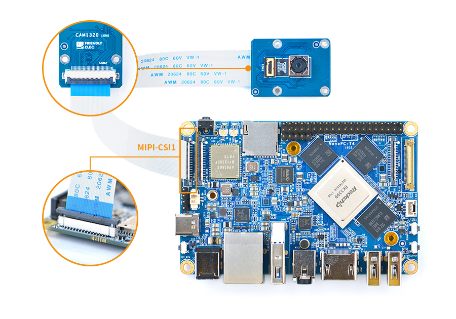
FriendlyELEC provides some scripts use to test a camera's functions. You can run it in a commandline to test picture taking and video recording.
You may try update this script to the lastest version by using the following commands:
cd /tmp/
git clone https://github.com/friendlyarm/gst-camera-sh.git
sudo cp gst-camera-sh/*.sh /usr/bin/
There are three scripts:
gst-camera.sh: preview, photo and video of a single camera
dual-camera.sh: preview two cameras
stop-gst-camera.sh: stop preview
11.1.1 Options in "gst-camera.sh"
Options Comment --index or -i Camera's index, it can be either 0 or 1. When two cameras are connected to a board you need to specify 1 to access the second camera. --action or -a Specify an action, it can be "preview" to preview, "photo" to take a picture or "video" to record video --output or -o Specify an output file to save a picture when taking a picture or video file when recording video --verbose or -v If it is specified as "yes" it will output the complete command when "gst-launch-1.0" is called -x Using the rkximagesink plugin, the preview image will be output to the X11 window for the FriendlyDesktop and Lubuntu systems -g Using the glimagesink plugin, the preview image will be output to the X11 window for the FriendlyDesktop and Lubuntu systems -k Using the kmssink plugin, the preview image will be output directly to the screen for the FriendlyCore system
The script gst-camera.sh will automatically recognize OV13850, OV4689 and C920 camera, and then pass the appropriate parameters to gst-launch-1.0.
11.1.2 Usage of gst-camera.sh
- Preview
gst-camera.sh --action preview- Picture Taking
You can run the following command to take a picture and save it as a "1.jpg" file,
gst-camera.sh -a photo -o 1.jpg
- Preview and Record
You can run the following command to record video and save your video to a "1.ts" file. Hardware encoding is activated when it is recording video.
gst-camera.sh --action video -output 1.ts
- Show Complete Command
If you add the "--verbose yes" option it will show a complete gsteamer command.
gst-camera.sh --action video --output 1.ts --verbose yes
Here is the complete gsteamer command you will see:
gst-launch-1.0 rkisp num-buffers=512 device=/dev/video0 io-mode=1 ! \
    video/x-raw,format=NV12,width=1280,height=720,framerate=30/1 ! \
        mpph264enc ! queue ! h264parse ! mpegtsmux ! \
        filesink location=/tmp/camera-record.ts
- Preview dual camera
Connect two mipi cameras, or one mipi camera and one usb camera (tested only: Logitech C920 pro), call the following command:
dual-camera.sh
Note: It is recommended to test this on FriendlyDesktop.
11.1.3 gst-launch-1.0 parameter description
Preview camera on FriendlyDesktop:
gst-launch-1.0 rkisp device=/dev/video1 io-mode=4 ! video/x-raw,format=NV12,width=1280,height=720,framerate=30/1 ! rkximagesink
Important parameters
parameter description device preview device(selfpath): /dev/video1 and /dev/video5, picture device(mainpath): /dev/video0 and /dev/video4, webcam device: /dev/video8 io-mode 1: memory map, 4:dmabuf rkximagesink/glimagesink/kmssink rkximagesink for FriendlyDesktop, kmssink for FriendlyCore, glimagesink for webcam on FriendlyDesktop
11.1.4 Access the camera in OpenCV
MIPI camera:
cv.VideoCapture('rkisp device=/dev/video1 io-mode=4 ! video/x-raw,format=NV12,width=640,height=480,framerate=30/1 ! videoconvert ! appsink', cv.CAP_GSTREAMER)
USB camera:
cv.VideoCapture('rkisp device=/dev/video8 io-mode=4 ! videoconvert ! video/x-raw,format=NV12,width=640,height=480,framerate=30/1 ! videoconvert ! appsink', cv.CAP_GSTREAMER)
Please refer to the sample code here for details:https://github.com/friendlyarm/install-opencv-on-friendlycore/tree/rk3399/examples
11.1.5 Camera application tutorial: Push video stream
Please refre this guide: How to setup RTMP server on NanoPC-T4
11.1.6 Reference resource
http://blog.iotwrt.com/media/2017/10/01/camera/ http://www.360doc.com/content/16/1019/17/496343_599664458.shtml
11.2 How to install and use docker
11.2.1 How to Install Docker
Run the following commands:
wget https://download.docker.com/linux/ubuntu/dists/bionic/pool/stable/arm64/containerd.io_1.2.6-3_arm64.deb
wget https://download.docker.com/linux/ubuntu/dists/bionic/pool/stable/arm64/docker-ce-cli_19.03.2~3-0~ubuntu-bionic_arm64.deb
wget https://download.docker.com/linux/ubuntu/dists/bionic/pool/stable/arm64/docker-ce_19.03.2~3-0~ubuntu-bionic_arm64.deb
sudo dpkg -i containerd.io_1.2.6-3_arm64.deb
sudo dpkg -i docker-ce-cli_19.03.2~3-0~ubuntu-bionic_arm64.deb
sudo dpkg -i docker-ce_19.03.2~3-0~ubuntu-bionic_arm64.deb
11.2.2 Test Docker installation
Test that your installation works by running the simple docker image:
git clone https://github.com/friendlyarm/debian-jessie-arm-docker
cd debian-jessie-arm-docker
./rebuild-image.sh
./run.sh
11.3 Using ffmpeg (video hardware decoding)
Both FriendlyCore and FriendlyDesktop systems are built-in ffmpeg, with bin file, static libraries, and header files, all stored in the /usr/ffmpeg-rkmp directory.
ffmpeg supports the RockChip MPP video decoder, for details, please refer to: https://trac.ffmpeg.org/wiki/HWAccelIntro
Test the decoding performance of 4K video:
/usr/ffmpeg-rkmp/bin/ffmpeg -benchmark -loglevel 48 -vcodec h264_rkmpp -i 4K-Chimei-inn-60mbps.mp4 -map 0:v:0 -f null -
The results are shown below:
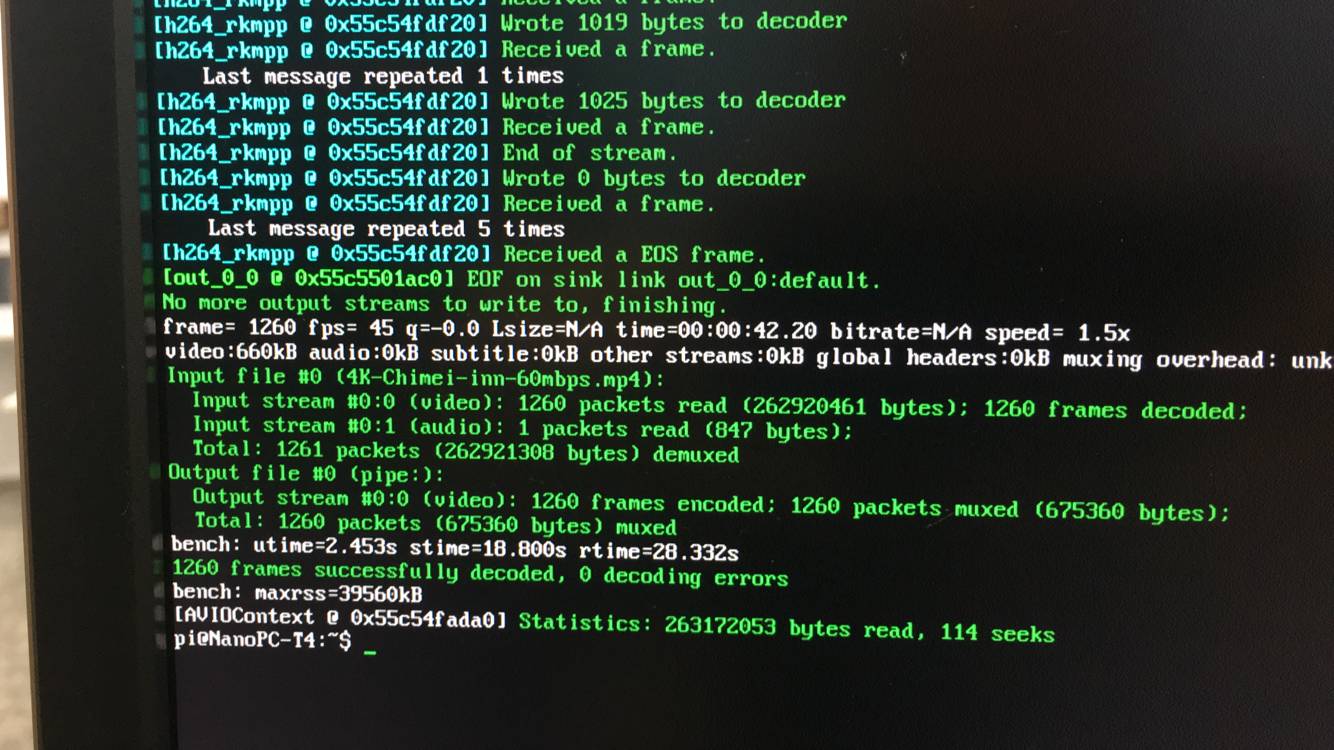
To play the video, you can use the ffmpeg-based player mpv. The 4K video used for the above test can be found in the test-video directory of the network disk. The network address is http://dl.friendlyelec.com/nanopct4.
12 Connect NVME SSD High Speed Hard Disk
12.1 Detection of SSD
root@FriendlyELEC:~# cat /proc/partitions
major minor  #blocks  name
   1        0       4096 ram0
 259        0  125034840 nvme0n1
If there is a nvme0n1 device node it means an SSD is recognized.
12.2 Partition of SSD
To mount an SSD under Linux we re-partition it as one section by running the following command:
(echo g; echo n; echo p; echo 1; echo ""; echo ""; echo w; echo q) | fdisk /dev/nvme0n1
If you want to re-partition it to multiple sections you can run "fdisk /dev/nvme0n1". For more detail about this command refer to the fdisk's manual.
12.3 Format Section to EXT4
After an SSD is successfully partitioned you can check its sections by running "cat /proc/partitions". The /dev/nvme0n1p1 section is used to store data:
root@FriendlyELEC:~# cat /proc/partitions
major minor  #blocks  name

   1        0       4096 ram0
 259        0  125034840 nvme0n1
 259        2  125033816 nvme0n1p1
The following command formats a section to ext4:
mkfs.ext4 /dev/nvme0n1p1
12.4 Auto Mount SSD on System Startup
Before we mount an SSD's section you need to know its Block ID. You can check it by running "blkid":
blkid /dev/nvme0n1p1
/dev/nvme0n1p1: UUID="d15c4bbf-a6c3-486f-8f81-35a8dbd46057" TYPE="ext4" PARTUUID="887628f0-01"
Add a "Block ID" to "/etc/fstab" and here is what it looks like
UUID=<Block ID> /media/nvme ext4 defaults 0 0
You need to replace <Block ID> with the UUID obtained by running "blkid". To mount the SSD in our example we made the "/etc/fstab" file as follows:
UUID=d15c4bbf-a6c3-486f-8f81-35a8dbd46057 /media/nvme ext4 defaults 0 0
We want to mount an SSD to "/media/nvme" but this directory doesn't exist. Therefore we create it and change its access right by running the following commands:
mkdir -p /media/nvme
chmod 777 /media/nvme
Run "mount" to check if the SSD is mounted successfully:
mount /media/nvme
You can reboot your board to check if your SSD will be automatically mounted:
reboot
12.5 Fan speed setting
The fan uses PWM to automatically adjust the speed. It determines the fan switch and the fan speed according to the current CPU temperature. If the current CPU temperature is not high, the fan will be turned off or rotated at a lower speed (reducing unnecessary environmental noise). ),
If you want the fan to start working immediately, you can use the following command to get the CPU running at high load immediately. This is one way to test if the fan works:
cpuburn
if you want to change the speed regulation behavior of the fan, please modify the following file:
/usr/bin/fa-fancontrol.sh # Entry, called by the pwm-fan.service service to control the fan in two ways, either by the kernel or by the user space by control the PWM.
/usr/bin/fa-fancontrol-direct.sh # Script to control the fan from user space by control the PWM to control the fan speed, etc. This script is called from the above script.
Need to cancel the boot automatically start the fan (such as you need to connect the other PWM device), please enter the following command:
systemctl stop pwm-fan
systemctl disable pwm-fan
Or delete the two files below:
/etc/systemd/system/pwm-fan.service
/etc/systemd/system/multi-user.target.wants/pwm-fan.service
12.6 Using 4G Module EC20 on Linux
Please see this article: How to use 4G Module on NanoPC-T4
13 Buildroot Linux
Buildroot is a simple, efficient and easy-to-use tool to generate embedded Linux systems through cross-compilation. It contains a boot-loader, kernel, rootfs, various libraries and utilities(e.g. qt, gstreamer, busybox etc).
FriendlyELEC's Buildroot is based on Rockchip's version which is made with linux-sdk and maintained with git. FriendlyELEC's version is synced with Rockchip's version;
- Rockchip's Buildroot: https://github.com/rockchip-linux/buildroot
- Buildroot's official site: https://buildroot.org
Here is what Buildroot for rockchip looks like
For a more detailed description of the Buildroot system, please refer to: Buildroot
14 Work with Lubuntu
See here: Lubuntu desktop 16.04 for RK3399
Using NVME SSD on Lubuntu: How to Initialize and Format New SSD And HDD
15 Work with Android 8.1
FriendlyElec provides a full Android8.1 BSP for NanoPC-T4. The source code is hosted at gitlab.com and is open source. The BSP supports GPU and VPU hardware acceleration.
15.1 Connect MIPI Camera to NanoPC-T4
FriendlyElec developed a MIPI camera CAM1320 for board and it works under Android. You can use this camera to take pictures and record video. The operation is straightforward. You just need to connect the camera at your board's MIPI interface, boot your board to Android and start Android's camera app.
The board has two MIPI interfaces: one front camera and the other rear camera:
MIPI-CSI1 <--> Android rear camera
MIPI-CSI2 <--> Android front camera
How to connect:
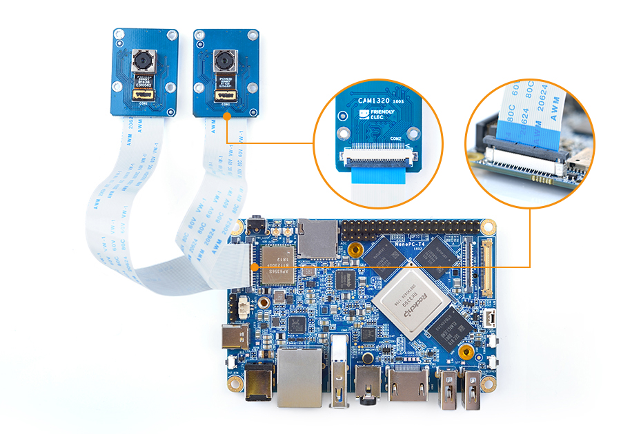
15.2 Use dual MIPI camera preview and video
Download the sample source code below from github and compile and run it:
git clone https://github.com/friendlyarm/Dual-Camera.git -b working-branch
After the application is installed, you need to Set Android permissions to make the demo run normally. The method is enter system ui: Settings -> Apps & notifications -> Dual Camera -> Permissions, Select the following permissions:
Camera
Microphone
Storage
The gui looks like this:
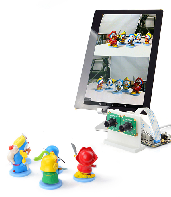
Click the "CAPTURE VIDEO" button on the gui to record the video (two cameras at the same time), and the video file will be saved to the following location.:/storage/emulated/0/Download/dualcamera_h264.mp4.
Known issue:
Recorded video file will play faster than normal, may need to adjust some parameters of mediacodec.
15.3 Change system language
The default system language of Android system is English. For example, if we want to set it to Chinese, the steps are as follows:
1) Go to Android settings:Settings -> System -> Languages & Input -> Languages;
2)Click "Add a language", Select "简体中文", and then select "中国";
3) At this time, there will be two languages, Chinese and English. Drag the Chinese item to the top of the list. Note that if you are using a mouse, drag it by placing the mouse pointer on the right side of the list item. On the icon and then press the middle mouse button to drag;
15.4 Android8.1 hardware access
You can use the FriendlyThings SDK to access and control hardware resources on the motherboard in the Android App, such as Uart, SPI, I2C, GPIO and other interfaces. For details, please refer to the following two documents.:
15.5 Android Neural Networks SDK Sample
Android8.1 BSP comes pre-installed with Rockchip's Android NN SDK for Android 8.1, supporting GPU acceleration.。
Sample program for Android NN pre-installed in the Android8 firmware we provide:TfLiteCameraDemo,This is a MobileNet classifier demo using Rockchip AndroidNN GPU acceleration,The camera module is required to be connected to the motherboard during operation. The USB camera and CSI camera are supported,The sample program is launched by clicking the "TfLiteCameraDemo" icon on the home page. The running effect is as follows:
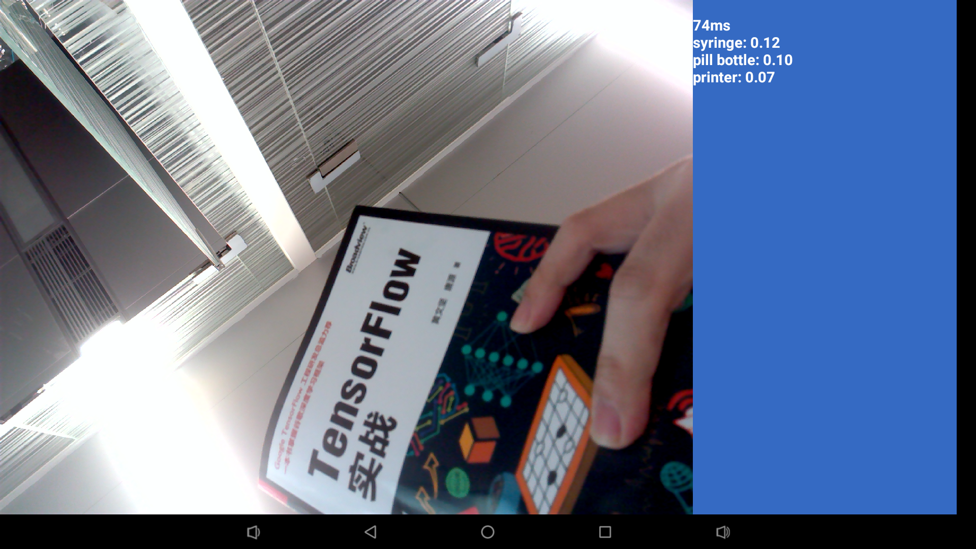
For a detailed description of the Android NN SDK, you can refer to this document:[RK3399_Android8.1_AndroidNN_SDK_V1.0_20180605发布说明.pdf]
TfLiteCameraDemo sample source code download link:[TfLiteCameraDemo source code]
15.6 Using the adb
1. The first time you start the system, if you need to change the system files, you need to turn off security verification (note: apk installation does not need to be closed), and restart after turning off security verification
adb root
adb disable-verity
adb reboot
2. After restarting, get root and remount /system to enable write permissions
adb root
adb remount
3. Upload a file
adb push example.txt /system/
15.7 HDMI resolution and overscan setting
If an HDMI display device is connected, go to Android Settings -> Display -> Advanced -> HDMI & Rotation to set it up.
HDMI Resolution The default is Auto, you can manually set the display resolution, up to 4K resolution Screen Zoom click the four arrow buttons in the middle to adjust the zoom Display Rotation for horizontal and vertical screen switching
15.8 Screen rotation
go to Android Settings -> Display -> Advanced -> HDMI & Rotation to set it up.
Use the following command in shell to test screen rotation (Settings not saved):
wm rotation 90Enter Settings -> Accessibility, Turn on immersive mode, and then open an Android application, For example: Lightning, it will be in full screen mode.
15.10 Switch audio output channel
You can configure the audio output to the HDMI or headphone jack, Setting interface entry method: Android Settings -> Accessibility -> Force audio output. If the Force audio output menu item is gray, that is, it is in an unselectable state, the hardware you are using will automatically detect the headphone plug-in status and automatically switch the audio channel without setting.
15.11 Adjust the volume of the recording
1) First use the amix command to adjust the volume of the recording through the serial port or the adb shell with root privileges, for example:
Amix "IN2 Boost"
Amix "ADC Capture Volume"
The above command is used to view the current settings.
2) After debugging, modify the value of the corresponding configuration item in the rt5651_main_mic_capture_controls array in the hardware/rockchip/audio/tinyalsa_hal/codec_config/rt5651_config.h file, compile the Android source code and test it.
15.12 Custom logo and boot animation
15.12.1 On/Off
Change:
BOOT_SHUTDOWN_ANIMATION_RINGING := false
to:
BOOT_SHUTDOWN_ANIMATION_RINGING := true
in device/rockchip/common/BoardConfig.mk file.
15.12.2 Boot animation
Create or replace the following files in the Android source code directory:
kernel/logo.bmp
kernel/logo_kernel.bmp
device/rockchip/common/bootshutdown/bootanimation.zip
15.12.3 Shutdown animation
Create or replace the following files in the Android source code directory:
device/rockchip/common/bootshutdown/shutdownanimation.zip
15.12.4 How to make animation
Please refre to:http://blog.sina.com.cn/s/blog_4960586c0100vu5v.html
15.13 Remove Google Framework
If you don't need to use the google service, you can delete the Google framework to save system resources by deleting the following directory in the Android source code and recompiling Android:
vendor/google
The NanoPC-T4 supports the FriendlyARM RC-100 remote control under Android. To get a better experience your can connect your T4 to an HDMI monitor and navigate Android.
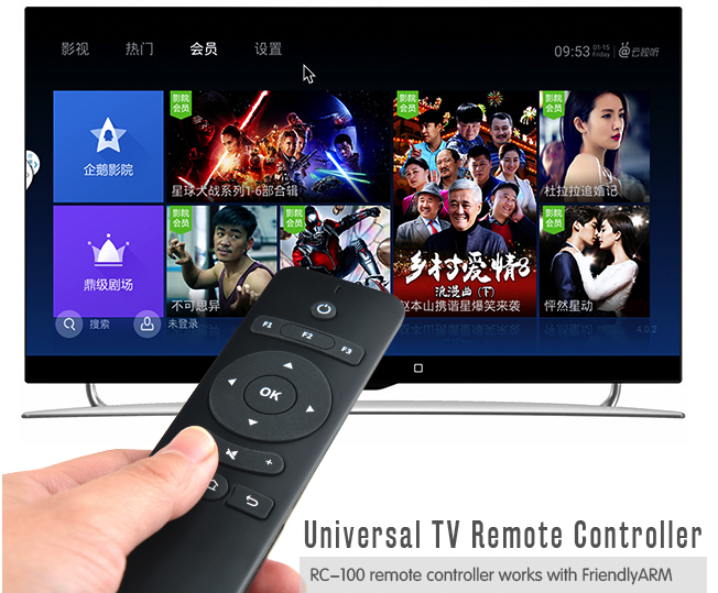
Here is a table for the remote control's keys and corresponding functions:
Key Function Up Navigate - Up Down Navigate - Down Left Navigate - Left Right Navigate - Right OK Confirm - Volume - + Volume + Mute Mute Menu Android Menu Home Android Home Return Android Return F1 Pull-Down Android Message Bar F2 Android Screenshot F3 Switch between mouse and key
15.15 Work with USB Camera to Take Pictures and Record Video
FriendlyELEC's Android system supports picture taking and video recording with a USB camera, Android's camera app has these functions. When you use the app to take pictures or record video you need to be aware of the following two things:
1) Make sure your camera's resolution works. We suggest you try a camera with a lower CIF resolution first. If it works you may switch to a camera with a higher resolution:
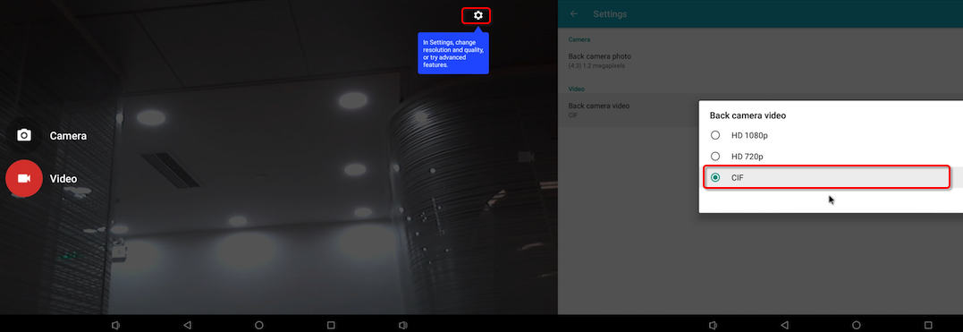 ;
;
2)A USB camera cannot work simultaneously with a MIPI camera. Plug and play is not supporter for camera modules. After you connect a camera to a board you need to reboot your board to enable the camera.
Here are the camera modules we tested: Logitech C270 and LogitechC922 PRO
In our test the resolution was 1080P when we used a Logitech C922 PRO to take pictures or record video.
15.16 Using 4G Module EC20 on Android
15.16.1 Hardware Setup
Connect an EC20 module to a USB to miniPCIe board and connect the board to an ARM board's USB Host. Here is a hardware setup:
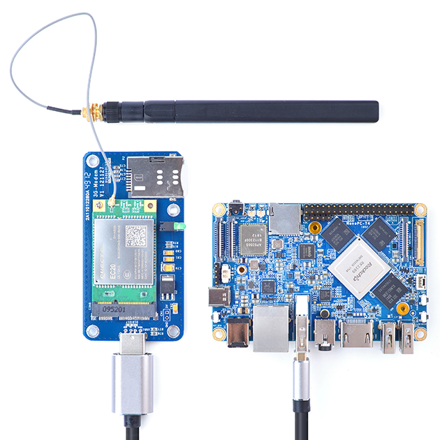
Power on the board and you will be able to surf the internet with the 4G module like using an Android phone.
15.16.2 Activate EC20's GPS Functions
By default GPS functions are disabled in Android. If GPS functions are enabled in Android but no GPS module is detected Android will continuously output log messages. After an EC20 module is connected you can enable GPS functions.
To enable the GPS functions open the "vendor/quectel/ec20/BoardConfigPartial.mk" file and change the following line:
BOARD_HAS_GPS := falseto
BOARD_HAS_GPS := trueand recompile Android。
15.17 Using SSD on Android
15.17.1 Step1: Format SSD as ext4
These steps need to be operated under the LINUX system.
For the convenience of operation, please switch to the root user with the following command on the terminal:
su -The default password for the root user is fa.
15.17.1.1 Detection of SSD
root@FriendlyELEC:~# cat /proc/partitions
major minor  #blocks  name
   1        0       4096 ram0
 259        0  125034840 nvme0n1
If there is a nvme0n1 device node it means an SSD is recognized.
15.17.1.2 Partition of SSD
To mount an SSD under Linux we re-partition it as one section by running the following command:
(echo o; echo n; echo p; echo 1; echo ""; echo ""; echo w; echo q) | fdisk /dev/nvme0n1
If you want to re-partition it to multiple sections you can run "fdisk /dev/nvme0n1". For more detail about this command refer to the fdisk's manual.
15.17.1.3 Format partition to EXT4
After an SSD is successfully partitioned you can check its partitions by running "cat /proc/partitions". The /dev/nvme0n1p1 partition is used to store data:
root@FriendlyELEC:~# cat /proc/partitions
major minor  #blocks  name

   1        0       4096 ram0
 259        0  125034840 nvme0n1
 259        2  125033816 nvme0n1p1
The following command formats a section to ext4:
mkfs.ext4 /dev/nvme0n1p1 -L SSD
15.17.2 Step2: Auto Mount SSD on Android System Startup
Android will automatically mount the SSD as an external storage device. No additional settings are required. Open the built-in Files application of Android and you can see that the SSD device is mounted:
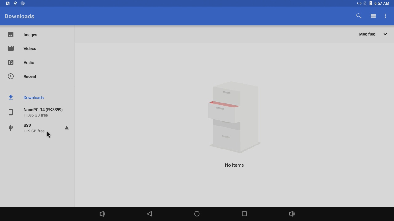
third-party software can recognize SSDs normally.
15.18 Fan speed setting
The fan uses PWM to achieve automatic speed regulation. It determines the fan switch and the fan speed according to the current CPU temperature. If the current CPU temperature is not high, the fan will be turned off or rotated at a lower speed (reducing unnecessary environment). Noise), if you want to change the fan's speed behavior, please modify the following files in the Android bsp source code:
device/rockchip/rk3399/nanopc-t4/pwm_fan.sh
Need to cancel the boot automatically start the fan (such as you need to connect other PWM devices), please modify the following files in the Android bsp source code:
device/rockchip/rk3399/init.rk3399.rc
After modifying the source code, you need to recompile Android.
16 Work with Android7.1
See here: Android7
17 How to Compile
17.1 Setup Development Environment
17.1.1 Method 1: Using docker to cross-compile
Please refre to docker-cross-compiler-novnc
17.1.2 Method 2: Setup build environment on the host machine
17.1.2.1 Install required packages
Install and run requirements ubuntu 20.04, install required packages using the following commands:
sudo apt-get -y update
sudo apt-get install -y sudo curl
sudo bash -c \
  "$(curl -fsSL https://raw.githubusercontent.com/friendlyarm/build-env-on-ubuntu-bionic/master/install.sh)"
The following cross-compilers will be installed:
| Version | Architecture | Compiler path | Purpose |
|---|---|---|---|
| 4.9.3 | armhf | /opt/FriendlyARM/toolchain/4.9.3 | Can be used to build 32-bit ARM applications |
| 6.4 | aarch64 | /opt/FriendlyARM/toolchain/6.4-aarch64 | Can be used to build kernel 4.4 |
| 11.3 | aarch64 | /opt/FriendlyARM/toolchain/11.3-aarch64 | Can be used to build kernel 4.19 or higher and U-Boot |
17.1.2.2 Setting the compiler path
Based on the table in the previous section, select the appropriate version of the compiler and add the compiler's path to PATH. For example, if you want to use the 11.3 cross-compiler, edit ~/.bashrc using vi and add the following content to the end:
export PATH=/opt/FriendlyARM/toolchain/11.3-aarch64/bin:$PATH
export GCC_COLORS=auto
Run the ~/.bashrc script to make it effective in the current commandline. Note: there is a space after ".":
. ~/.bashrcTo verify if the installation was successful:
$ aarch64-linux-gcc -v
Using built-in specs.
COLLECT_GCC=aarch64-linux-gcc
COLLECT_LTO_WRAPPER=/opt/FriendlyARM/toolchain/11.3-aarch64/libexec/gcc/aarch64-cortexa53-linux-gnu/11.3.0/lto-wrapper
Target: aarch64-cortexa53-linux-gnu
Configured with: /home/cross/arm64/src/gcc/configure --build=x86_64-build_pc-linux-gnu --host=x86_64-build_pc-linux-gnu --target=aarch64-cortexa53-linux-gnu --prefix=/opt/FriendlyARM/toolchain/11.3-aarch64 --exec_prefix=/opt/FriendlyARM/toolchain/11.3-aarch64 --with-sysroot=/opt/FriendlyARM/toolchain/11.3-aarch64/aarch64-cortexa53-linux-gnu/sysroot --enable-languages=c,c++ --enable-fix-cortex-a53-843419 --with-arch=armv8-a+crypto+crc --with-cpu=cortex-a53 --with-pkgversion=ctng-1.25.0-119g-FA --with-bugurl=http://www.friendlyelec.com/ --enable-objc-gc --enable-__cxa_atexit --disable-libmudflap --disable-libgomp --disable-libssp --disable-libquadmath --disable-libquadmath-support --disable-libsanitizer --disable-libmpx --with-gmp=/home/cross/arm64/buildtools --with-mpfr=/home/cross/arm64/buildtools --with-mpc=/home/cross/arm64/buildtools --with-isl=/home/cross/arm64/buildtools --enable-lto --enable-threads=posix --disable-libstdcxx-pch --enable-clocale=gnu --enable-libstdcxx-time=yes --with-default-libstdcxx-abi=new --enable-gnu-indirect-function --enable-gnu-unique-object --enable-default-pie --enable-linker-build-id --with-linker-hash-style=gnu --enable-plugin --enable-gold --with-libintl-prefix=/home/cross/arm64/buildtools --disable-multilib --with-local-prefix=/opt/FriendlyARM/toolchain/11.3-aarch64/aarch64-cortexa53-linux-gnu/sysroot --enable-long-long --enable-checking=release --enable-link-serialization=2
Thread model: posix
Supported LTO compression algorithms: zlib
gcc version 11.3.0 (ctng-1.25.0-119g-FA)
17.2 Build Openwrt/Friendlywrt
17.2.1 Download Code
Two versions are available, please choose as required:
17.2.1.1 FriendlyWrt 21.02
mkdir friendlywrt21-rk3399
cd friendlywrt21-rk3399
git clone https://github.com/friendlyarm/repo --depth 1 tools
tools/repo init -u https://github.com/friendlyarm/friendlywrt_manifests -b master-v21.02 \
        -m rk3399.xml --repo-url=https://github.com/friendlyarm/repo  --no-clone-bundle
tools/repo sync -c  --no-clone-bundle
17.2.1.2 FriendlyWrt 23.05
mkdir friendlywrt23-rk3399
cd friendlywrt23-rk3399
git clone https://github.com/friendlyarm/repo --depth 1 tools
tools/repo init -u https://github.com/friendlyarm/friendlywrt_manifests -b master-v23.05 \
        -m rk3399.xml --repo-url=https://github.com/friendlyarm/repo  --no-clone-bundle
tools/repo sync -c  --no-clone-bundle
17.2.2 First compilation step
./build.sh rk3399.mk # or rk3399-docker.mk
All the components (including u-boot, kernel, and friendlywrt) are compiled and the sd card image will be generated, then execute the following command to generate the image file for installing the system into the emmc:
./build.sh emmc-imgAfter making changes to the project, the sd card image needs to be repackaged by running the following command:
./build.sh sd-img17.2.3 Secondary compilation steps
cd friendlywrt
make menuconfig
rm -rf ./tmp
make -j${nproc}
cd ../
./build.sh sd-img
./build.sh emmc-img
17.2.4 Build u-boot only
./build.sh uboot17.2.5 Build kernel only
./build.sh kernel17.2.6 Build friendlywrt only
./build.sh friendlywrtOr go to the friendlywrt directory and follow the standard openwrt commands. If you get an error with the above command, try using the following command to compile in a single thread:
cd friendlywrt
make -j1 V=s
17.3 Build Buildroot
please refer to: Buildroot
17.4 Build Other Linux
17.4.1 Kernel and u-boot versions
| Operating System | Kernel Version | U-boot version | Cross-compiler | Partition type | Packaging Tool | Kernel branch | Kernel configuration | U-boot branch | U-boot configuration |
|---|---|---|---|---|---|---|---|---|---|
| lubuntu | linux v4.4.y | u-boot v2014.10 | 6.4-aarch64 |
MBR | sd-fuse | nanopi4-linux-v4.4.y | nanopi4_linux_defconfig | nanopi4-v2014.10_oreo | rk3399_defconfig |
| friendlycore-arm64 | |||||||||
| friendlydesktop-arm64 | |||||||||
| eflasher | |||||||||
| buildroot | linux v4.19.y | u-boot v2017.09 |
11.3-aarch64 | GPT | sd-fuse | nanopi4-v4.19.y | nanopi4_linux_defconfig | nanopi4-v2017.09 | nanopi4_defconfig |
| ubuntu-focal-desktop-arm64 | |||||||||
| debian-bullseye-desktop-arm64 | |||||||||
| debian-bullseye-minimal-arm64 | |||||||||
| friendlycore-focal-arm64 | |||||||||
| debian-bookworm-core-arm64 | |||||||||
| ubuntu-noble-core-arm64 | |||||||||
| openmediavault-arm64 | linux v6.1.y | u-boot v2017.09 |
11.3-aarch64 | GPT | sd-fuse |
nanopi-r2-v6.1.y |
nanopi4_linux_defconfig | ||
| friendlywrt21 | GPT | nanopi4_linux_defconfig +friendlywrt.config | |||||||
| friendlywrt21-docker | |||||||||
| friendlywrt23 | |||||||||
| friendlywrt23-docker |
- Kernel git repo:https://github.com/friendlyarm/kernel-rockchip
- U-boot git repo:https://github.com/friendlyarm/uboot-rockchip
- The cross-compile toolchain is located in the path: /opt/FriendlyARM/toolchain/
- The SD-Fuse is a helper script to make bootable SD card image.
- Click on MBR and GPT in the table to view the partition layout (configuration file) for each system.
17.4.2 Build kernel linux-v4.4.y
This section applies to the following operating systems:
| lubuntu | eflasher | friendlydesktop-arm64 | friendlycore-arm64 |
Clone the repository to your local drive then build:
git clone https://github.com/friendlyarm/kernel-rockchip --single-branch --depth 1 -b nanopi4-linux-v4.4.y kernel-rockchip
cd kernel-rockchip
export PATH=/opt/FriendlyARM/toolchain/6.4-aarch64/bin/:$PATH
touch .scmversion
# Load configuration
make ARCH=arm64 CROSS_COMPILE=aarch64-linux- nanopi4_linux_defconfig
# Optionally, if you want to change the default kernel config
# make ARCH=arm64 CROSS_COMPILE=aarch64-linux- menuconfig
# Start building kernel
make ARCH=arm64 CROSS_COMPILE=aarch64-linux- nanopi4-images -j$(nproc)
# Start building kernel modules
mkdir -p out-modules
make ARCH=arm64 CROSS_COMPILE=aarch64-linux- INSTALL_MOD_PATH="$PWD/out-modules" modules -j$(nproc)
make ARCH=arm64 CROSS_COMPILE=aarch64-linux- INSTALL_MOD_PATH="$PWD/out-modules" modules_install
KERNEL_VER=$(make CROSS_COMPILE=aarch64-linux-gnu- ARCH=arm64 kernelrelease)
rm -rf $PWD/out-modules/lib/modules/${KERNEL_VER}/kernel/drivers/gpu/arm/mali400/
[ ! -f "$PWD/out-modules/lib/modules/${KERNEL_VER}/modules.dep" ] && depmod -b $PWD/out-modules -E Module.symvers -F System.map -w ${KERNEL_VER}
(cd $PWD/out-modules && find . -name \*.ko | xargs aarch64-linux-strip --strip-unneeded)
After the compilation, the following files will be generated:
| kernel.img | resource.img | The kernel modules are located in the out-modules directory |
Run your build:
Please refre to #Running the build
17.4.3 Build u-boot v2014.10
This section applies to the following operating systems:
| lubuntu | eflasher | friendlydesktop-arm64 | friendlycore-arm64 |
Clone the repository to your local drive then build:
git clone https://github.com/friendlyarm/uboot-rockchip --single-branch --depth 1 -b nanopi4-v2014.10_oreo
cd uboot-rockchip
export PATH=/opt/FriendlyARM/toolchain/6.4-aarch64/bin/:$PATH
make CROSS_COMPILE=aarch64-linux- rk3399_defconfig
make CROSS_COMPILE=aarch64-linux-
After the compilation, the following files will be generated:
| uboot.img | trust.img | rk3399_loader_v1.22.119.bin (aka MiniLoaderAll.bin) |
Installing the u-boot:
Please refre to #Running the build
17.4.4 Build kernel linux-v4.19.y
This section applies to the following operating systems:
| ubuntu-focal-desktop-arm64 | debian-bullseye-desktop-arm64 | debian-bullseye-minimal-arm64 | friendlycore-focal-arm64 | ubuntu-noble-core-arm64 | debian-bookworm-core-arm64 | buildroot |
Clone the repository to your local drive then build:
git clone https://github.com/friendlyarm/kernel-rockchip --single-branch --depth 1 -b nanopi4-v4.19.y kernel-rockchip
cd kernel-rockchip
export PATH=/opt/FriendlyARM/toolchain/11.3-aarch64/bin/:$PATH
touch .scmversion
# Configuring the Kernel
# Load default configuration
make ARCH=arm64 CROSS_COMPILE=aarch64-linux- nanopi4_linux_defconfig
# Optionally, load configuration for FriendlyWrt
# make ARCH=arm64 CROSS_COMPILE=aarch64-linux- nanopi4_linux_defconfig friendlywrt.config
# Optionally, if you want to change the default kernel config
# make ARCH=arm64 CROSS_COMPILE=aarch64-linux- menuconfig
# Start building kernel
make ARCH=arm64 CROSS_COMPILE=aarch64-linux- nanopi4-images -j$(nproc)
# Start building kernel modules
mkdir -p out-modules
make ARCH=arm64 CROSS_COMPILE=aarch64-linux- INSTALL_MOD_PATH="$PWD/out-modules" modules -j$(nproc)
make ARCH=arm64 CROSS_COMPILE=aarch64-linux- INSTALL_MOD_PATH="$PWD/out-modules" modules_install
KERNEL_VER=$(make CROSS_COMPILE=aarch64-linux-gnu- ARCH=arm64 kernelrelease)
rm -rf $PWD/out-modules/lib/modules/${KERNEL_VER}/kernel/drivers/gpu/arm/mali400/
[ ! -f "$PWD/out-modules/lib/modules/${KERNEL_VER}/modules.dep" ] && depmod -b $PWD/out-modules -E Module.symvers -F System.map -w ${KERNEL_VER}
(cd $PWD/out-modules && find . -name \*.ko | xargs aarch64-linux-strip --strip-unneeded)
After the compilation, the following files will be generated:
| kernel.img | resource.img | The kernel modules are located in the out-modules directory |
Run your build:
Please refre to #Running the build
17.4.5 Build kernel linux-v6.1.y
This section applies to the following operating systems:
| friendlywrt21 | friendlywrt21-docker | friendlywrt23 | friendlywrt23-docker | openmediavault-arm64 |
Clone the repository to your local drive then build:
git clone https://github.com/friendlyarm/kernel-rockchip --single-branch --depth 1 -b nanopi-r2-v6.1.y kernel-rockchip
cd kernel-rockchip
export PATH=/opt/FriendlyARM/toolchain/11.3-aarch64/bin/:$PATH
touch .scmversion
# Configuring the Kernel
# Load default configuration
make CROSS_COMPILE=aarch64-linux-gnu- ARCH=arm64 nanopi4_linux_defconfig
# Optionally, load configuration for FriendlyWrt
# make CROSS_COMPILE=aarch64-linux-gnu- ARCH=arm64 nanopi4_linux_defconfig friendlywrt.config
# Optionally, if you want to change the default kernel config
# make CROSS_COMPILE=aarch64-linux-gnu- ARCH=arm64 menuconfig
# Start building kernel
make CROSS_COMPILE=aarch64-linux-gnu- ARCH=arm64 -j$(nproc)
# Start building kernel modules
mkdir -p out-modules && rm -rf out-modules/*
make CROSS_COMPILE=aarch64-linux-gnu- ARCH=arm64 INSTALL_MOD_PATH="$PWD/out-modules" modules -j$(nproc)
make CROSS_COMPILE=aarch64-linux-gnu- ARCH=arm64 INSTALL_MOD_PATH="$PWD/out-modules" modules_install
KERNEL_VER=$(make CROSS_COMPILE=aarch64-linux-gnu- ARCH=arm64 kernelrelease)
[ ! -f "$PWD/out-modules/lib/modules/${KERNEL_VER}/modules.dep" ] && depmod -b $PWD/out-modules -E Module.symvers -F System.map -w ${KERNEL_VER}
(cd $PWD/out-modules && find . -name \*.ko | xargs aarch64-linux-strip --strip-unneeded)
Pack the kernel.img and resource.img:
wget https://raw.githubusercontent.com/friendlyarm/sd-fuse_rk3399/kernel-6.1.y/tools/mkkrnlimg && chmod 755 mkkrnlimg
wget https://raw.githubusercontent.com/friendlyarm/sd-fuse_rk3399/kernel-6.1.y/tools/resource_tool && chmod 755 resource_tool
wget https://raw.githubusercontent.com/friendlyarm/sd-fuse_rk3399/kernel-6.1.y/prebuilt/boot/logo.bmp
wget https://raw.githubusercontent.com/friendlyarm/sd-fuse_rk3399/kernel-6.1.y/prebuilt/boot/logo_kernel.bmp
./mkkrnlimg arch/arm64/boot/Image kernel.img
mkdir kernel-dtbs
cp -f arch/arm64/boot/dts/rockchip/rk3399-nanopi-r4s.dtb kernel-dtbs/rk3399-nanopi4-rev09.dtb
cp -f arch/arm64/boot/dts/rockchip/rk3399-nanopi-r4s.dtb kernel-dtbs/rk3399-nanopi4-rev0a.dtb
cp -f arch/arm64/boot/dts/rockchip/rk3399-nanopi-r4se.dtb kernel-dtbs/rk3399-nanopi4-rev0b.dtb
cp -f arch/arm64/boot/dts/rockchip/rk3399-nanopc-t4.dtb kernel-dtbs/rk3399-nanopi4-rev00.dtb
./resource_tool --dtbname kernel-dtbs/*.dtb logo.bmp logo_kernel.bmp
After the compilation, the following files will be generated:
| kernel.img | resource.img | The kernel modules are located in the out-modules directory |
Run your build:
Please refre to #Running the build
17.4.6 Build u-boot v2017.09
This section applies to the following operating systems:
| ubuntu-focal-desktop-arm64 | debian-bullseye-desktop-arm64 | debian-bullseye-minimal-arm64 | friendlycore-focal-arm64 | ubuntu-noble-core-arm64 | debian-bookworm-core-arm64 | buildroot |
Clone the repository to your local drive then build:
git clone https://github.com/friendlyarm/rkbin --single-branch --depth 1 -b friendlyelec
git clone https://github.com/friendlyarm/uboot-rockchip --single-branch --depth 1 -b nanopi4-v2017.09
export PATH=/opt/FriendlyARM/toolchain/11.3-aarch64/bin/:$PATH
cd uboot-rockchip/
./make.sh nanopi4
After the compilation, the following files will be generated:
| uboot.img | trust.img | rk3399_loader_v1.24.126.bin (aka MiniLoaderAll.bin) |
Run your build:
Please refre to #Running the build
17.4.7 Running the build
17.4.7.1 Install to target board
17.4.7.1.1 MBR partition
This section applies to the following operating systems:
| lubuntu | eflasher | friendlydesktop-arm64 | friendlycore-arm64 |
The MBR partitioning is only used by the Linux v4.4 kernel. You can check the partition layout by clicking on this link: partmap. To write an image file, you can use the dd command. For example, in the parameter.template file, "0x00014000@0x00014000(kernel)" specifies that the kernel partition starts at 0x00014000, which is equivalent to 81920 in decimal. Therefore, the dd command should be as follows:
dd if=kernel.img of=/dev/mmcblk0 seek=81920
17.4.7.1.2 GPT partition
This section applies to the following operating systems:
| ubuntu-focal-desktop-arm64 | debian-bookworm-core-arm64 | debian-bullseye-desktop-arm64 | debian-bullseye-minimal-arm64 |
| friendlycore-focal-arm64 | ubuntu-noble-core-arm64 | friendlywrt21-kernel4 | buildroot |
| friendlywrt21 | friendlywrt21-docker | friendlywrt23 | friendlywrt23-docker |
The OS uses GPT partitions by default which is using the Linux v4.19 and Linux v5.15 kernel, you can use the dd command, but be careful to choose the right output device:
- The SD/TF Card device node: /dev/mmcblk0
- The eMMC device node: /dev/mmcblk2
The following is an example of how to update the kernel to eMMC:
Use the 'parted' command to view the partition layout:
parted /dev/mmcblk2 print
Sample outputs:
Model: MMC BJTD4R (sd/mmc)
Disk /dev/mmcblk2: 31.3GB
Sector size (logical/physical): 512B/512B
Partition Table: gpt
Disk Flags:

Number  Start   End     Size    File system  Name      Flags
 1      8389kB  12.6MB  4194kB               uboot
 2      12.6MB  16.8MB  4194kB               trust
 3      16.8MB  21.0MB  4194kB               misc
 4      21.0MB  25.2MB  4194kB               dtbo
 5      25.2MB  41.9MB  16.8MB               resource
 6      41.9MB  83.9MB  41.9MB               kernel
 7      83.9MB  134MB   50.3MB               boot
 8      134MB   2500MB  2366MB  ext4         rootfs
 9      2500MB  31.3GB  28.8GB  ext4         userdata
as shown above, the resource partition is located at 5 and the kernel partition is located at 6. Use the dd command to write the resource.img and kernel.img files to these partitions, the commands are as follows:
dd if=resource.img of=/dev/mmcblk2p5 bs=1M
dd if=kernel.img of=/dev/mmcblk2p6 bs=1M
If you want to update u-boot:
dd if=uboot.img of=/dev/mmcblk2p1 bs=1M
To update new driver modules, copy the newly compiled driver modules to the appropriate directory under /lib/modules.
17.4.7.2 Packaging and creating an SD image
To create a new OS image file, you need to use the "sd-fuse" packaging tool.
"sd-fuse" is a collection of scripts that can be used to create bootable SD card images for FriendlyElec boards. Its main features include:
- Creation of root filesystem images from a directory
- Building of bootable SD card images
- Simple compilation of kernel, U-Boot, and third-party drivers
Please click on the following link to find out more:
| Kernel version | Packaging Tool |
|---|---|
| linux v4.4.y | sd-fuse |
| linux v4.19.y | sd-fuse_rk3399/kernel-4.19 |
| linux v6.1.y | sd-fuse_rk3399/kernel-6.1.y |
17.4.7.3 USB flashing
Note: kernel v4.4.y is not supported
17.4.7.3.1 Linux
Reboot the board and enter loader mode with the following command:
sudo reboot loaderTo flash U-Boot and kernel using the "upgrade_tool_v2.17_for_linux" tool, please use the following command:
sudo upgrade_tool di -k kernel.img
sudo upgrade_tool di -re resource.img
sudo upgrade_tool di -u uboot.img
sudo upgrade_tool RD
Note: "upgrade_tool" is a command-line tool provided by Rockchip for Linux operating systems (Linux_Upgrade_Tool).
17.5 Build the code using scripts
17.5.1 Download scripts and image files
git clone https://github.com/friendlyarm/sd-fuse_rk3399.git -b kernel-4.19
cd sd-fuse_rk3399
wget http://112.124.9.243/dvdfiles/RK3399/images-for-eflasher/friendlycore-focal-arm64-images.tgz
tar xvzf friendlycore-focal-arm64-images.tgz
17.5.2 Compile the kernel
Download the kernel source code and compile it. the relevant image files in the friendlycore-focal-arm64 directory will be automatically updated, including the kernel modules in the file system:
git clone https://github.com/friendlyarm/kernel-rockchip --depth 1 -b nanopi4-v4.19.y kernel-rk3399
KERNEL_SRC=$PWD/kernel-rk3399 ./build-kernel.sh friendlycore-focal-arm64
17.5.3 Compile the kernel headers
git clone https://github.com/friendlyarm/kernel-rockchip --depth 1 -b nanopi4-v4.19.y kernel-rk3399
MK_HEADERS_DEB=1 BUILD_THIRD_PARTY_DRIVER=0 KERNEL_SRC=$PWD/kernel-rk3399 ./build-kernel.sh friendlycore-focal-arm64
17.5.4 Compile the uboot
Download the uboot source code and compile it. the relevant image files in the friendlycore-focal-arm64 directory will be automatically updated:
git clone https://github.com/friendlyarm/uboot-rockchip --depth 1 -b nanopi4-v2017.09
UBOOT_SRC=$PWD/uboot-rockchip ./build-uboot.sh friendlycore-focal-arm64
17.5.5 Generate new image
Repackage the image file in the friendlycore-focal-arm64 directory into sd card image:
./mk-sd-image.sh friendlycore-focal-arm64After the command is completed, the image is in the out directory, you can use the dd command to make the SD boot card, for example:
dd if=out/rk3399-sd-friendlycore-focal-4.19-arm64-YYYYMMDD.img of=/dev/sdX bs=1M
17.6 Building AOSP from source
17.6.1 Hardware and Software Requirements
- Your computer should have at least 16GB of RAM and 300GB of disk space. We recommend using a machine with 32GB of RAM and a large-capacity, high-speed SSD, and we do not recommend using virtual machines.
- If you encounter compilation errors, they may be caused by problems with the compilation environment. We recommend using the following Docker container for compilation: docker-cross-compiler-novnc.
17.6.2 Compile Android10
17.6.2.1 Download Android10 Source Code
There are two ways to download the source code:
- repo archive file on netdisk
Netdisk URL: Click here
File location on netdisk:"07_Source codes/rk3399-android-10.git-YYYYMMDD.tar.xz" (YYYYMMDD means the date of packaging)
After extracting the repo package from the network disk, you need to execute the sync.sh script, which will pull the latest code from gitlab:
tar xf "/path/to/netdisk/07_Source codes/rk3399-android-10.git-YYYYMMDD.tar.xz"
cd rk3399-android-10
./sync.sh
- git clone from gitlab
NanoPC-T4 source code is maintained in gitlab, You can download it by running the following command:
git clone --recursive https://gitlab.com/friendlyelec/rk3399-android-10.git -b main
Note: If the following error "error: unknown option `recurse-submodules'" appears, please upgrade git to v2.0.0 or above.
17.6.2.2 Generate Image File
You can compile an Android source code and generate an image file (non-root user is recommended):
cd rk3399-android-10
./build-nanopc-t4.sh -F -M
If you need to include google apps, you need to set an environment variable and then compile, as shown below:
cd rk3399-android-10
export INSTALL_GAPPS_FOR_TESTING=yes
./build-nanopc-t4.sh -F -M
17.6.2.3 Make OTA Packages
If you need the support of A/B (Seamless) System Updates, you need to do the following:
a) Build your own update server for http download of update files;
b) Customize the Updater application, the code is located in packages/apps/Updater, let it connect and download file from your server;
c) Use the quick compilation script parameter -O or --ota to compile OTA Packages, as shown below:
cd rk3399-android-10
./build-nanopc-t4.sh -F -O -M
After the compilation is successfully completed, the OTA update related packages are located in the directory: rockdev/otapackage/ ,Please do not delete this directory.
After you have made some changes, compiling again with the parameter -O will generate ota-update-XXXXXXXX.zip, which is an incremental update package.
OTA Packages decides whether to generate incremental update package according to BUILD_NUMBER, for details, please refer to build-nanopc-t4.sh.
To disable the A/B feature, you can refer to the following to modify device/rockchip/rk3399/nanopc-t4/BoardConfig.mk, and then recompile uboot and android:
BOARD_USES_AB_IMAGE := false
17.6.2.4 Update System with New Image
After compilation is done a new image file will be generated in the "rockdev/Image-nanopc_t4/" directory under Android 10's source code directory. You can follow the steps below to update the OS in NanoPC-T4:
1) Insert an SD card which is processed with EFlasher to an SD card reader and insert this reader to a PC running Ubuntu. The SD card's partitions will be automatically mounted;
2) Copy all the files under the "rockdev/Image-nanopc_t4/" directory to the SD card's android10 directory in the "FRIENDLYARM" partition;
3) Insert this SD card to NanoPC-T4 and reflash Android
When flashing Android 10, EFlasher requires v1.3 or above. When flashing with Type-C, please use the tool AndroidTool v2.71 or Linux_Upgrade_Tool v1.49 provided by Rockchip.
17.6.3 Compile Android8.1
17.6.3.1 Download Android8.1 Source Code
There are two ways to download the source code:
- repo archive file on netdisk
Netdisk URL: Click here
File location on netdisk:sources/rk3399-android-8.1.git-YYYYMMDD.tgz (YYYYMMDD means the date of packaging)
After extracting the repo package from the network disk, you need to execute the sync.sh script, which will pull the latest code from gitlab:
tar xvzf /path/to/netdisk/sources/rk3399-android-8.1.git-YYYYMMDD.tgz
cd rk3399-android-8.1
./sync.sh
- git clone from gitlab
NanoPC-T4 source code is maintained in gitlab, You can download it by running the following command:
git clone https://gitlab.com/friendlyelec/rk3399-android-8.1 --depth 1 -b master
17.6.3.2 Generate Image File
You can compile an Android source code and generate an image file:
cd rk3399-android-8.1
./build-nanopc-t4.sh -F -M
17.6.3.3 Update System with New Image
After compilation is done a new image file will be generated in the "rockdev/Image-nanopc_t4/" directory under Android 8.1's source code directory. You can follow the steps below to update the OS in NanoPC-T4:
1) Insert an SD card which is processed with EFlasher to an SD card reader and insert this reader to a PC running Ubuntu. The SD card's partitions will be automatically mounted;
2) Copy all the files under the "rockdev/Image-nanopc_t4/" directory to the SD card's android8 directory in the "FRIENDLYARM" partition;
3) Insert this SD card to NanoPC-T4 and reflash Android
Here is an alternative guide to update OS: sd-fuse_rk3399
17.6.4 Compile Android7
17.6.4.1 Download Android7 Source Code
There are two ways to download the source code:
- repo archive file on netdisk
Netdisk URL: Click here
File location on netdisk:sources/rk3399-android-7.git-YYYYMMDD.tgz (YYYYMMDD means the date of packaging)
After extracting the repo package from the network disk, you need to execute the sync.sh script, which will pull the latest code from gitlab:
tar xvzf /path/to/netdisk/sources/rk3399-android-7.git-YYYYMMDD.tgz
cd rk3399-nougat
./sync.sh
- git clone from gitlab
NanoPC-T4 source code is maintained in gitlab, You can download it by running the following command:
git clone https://gitlab.com/friendlyelec/rk3399-nougat --depth 1 -b nanopc-t4-nougat
17.6.4.2 Generate Image File
You can compile an Android7 source code and generate an image file:
cd rk3399-nougat
./build-nanopc-t4.sh -F -M
17.6.4.3 Update System with New Image
After compilation is done a new image file will be generated in the "rockdev/Image-nanopc_t4/" directory under Android7's source code directory. You can follow the steps below to update the OS in NanoPC-T4:
1) Insert an SD card which is processed with EFlasher to an SD card reader and insert this reader to a PC running Ubuntu. The SD card's partitions will be automatically mounted;
2) Copy all the files under the "rockdev/Image-nanopc_t4/" directory to the SD card's android8 directory in the "FRIENDLYARM" partition;
3) Insert this SD card to NanoPC-T4 and reflash Android
Here is an alternative guide to update OS: sd-fuse_rk3399
18 Access hardware
18.1 Access Serial Interface
For now only UART4 is available for users:
Serial Interface Serial Device UART0 Used by Bluetooth UART1 Used by Gbps Ethernet UART2 Used by Serial Debug Port UART3 Used by Gbps Ethernet UART4 Available, device name is /dev/ttyS4 (note: this is only applicable for ROM released after 20180618)
19 Backup rootfs and create custom SD image (to burn your application into other boards)
19.1 Backup rootfs
Run the following commands on your target board. These commands will back up the entire root partition:
sudo passwd root
su root
cd /
tar --warning=no-file-changed -cvpzf /rootfs.tar.gz \
    --exclude=/rootfs.tar.gz --exclude=/var/lib/docker/runtimes \
    --exclude=/etc/firstuser --exclude=/etc/friendlyelec-release \
    --exclude=/usr/local/first_boot_flag --one-file-system /
Note: if there is a mounted directory on the system, an error message will appear at the end, which can be ignored.
19.2 Making a bootable SD card from a root filesystem
Run the following script on your Linux PC host, we'll only mention "debian-bullseye-desktop-arm64 os" for brevity, but you can apply the same process for every linux OS.
su root
git clone https://github.com/friendlyarm/sd-fuse_rk3399 --single-branch -b kernel-4.19
cd sd-fuse_rk3399
tar xvzf /path/to/netdrive/03_Partition\ image\ files/debian-bullseye-desktop-arm64-images.tgz
tar xvzf /path/to/netdrive/03_Partition\ image\ files/emmc-eflasher-images.tgz
scp pi@BOARDIP:/rootfs.tar.gz /rootfs.tar.gz
mkdir rootfs
tar xvzfp rootfs.tar.gz -C rootfs --numeric-owner --same-owner
./build-rootfs-img.sh rootfs debian-bullseye-desktop-arm64
./mk-sd-image.sh debian-bullseye-desktop-arm64
./mk-emmc-image.sh debian-bullseye-desktop-arm64 autostart=yes
20 Configuring kernel command line parameters (only support for kernel4.4)
20.1 eMMC Boot
Here are the steps:
Make an eflahser bootable SD card (use the firmware file starting with rk3xxxx-eflasher-),
Insert the SD card into your computer, go to the SD card's OS-related directory, and edit the file parameter.txt, which is a text file containing command-line parameters,
Then boot from the SD card and burn the system to the eMMC.
20.2 SD Boot
To modify the command line parameters of the SD card, you need to repackage the SD card image file,
you can use the sd-fuse script we provide to assist packaging:
git clone https://github.com/friendlyarm/sd-fuse_rk3399.git -b master --single-branch
cd sd-fuse_rk3399
tar xvzf /path/to/netdrive/03_Partition\ image\ files/friendlydesktop-arm64-images.tgz
tar xvzf /path/to/netdrive/03_Partition\ image\ files/emmc-flasher-images.tgz
vim friendlydesktop-arm64/parameter.txt   # Edit command-line parameters
./mk-sd-image.sh friendlydesktop-arm64    # Repackage sd image file
./mk-emmc-image.sh friendlydesktop-arm64  # Repackage sd-to-emmc image file
21 Common Linux-based operating system operations
21.1 Using ADB on Linux Systems
21.1.1 Enabling ADB in Buildroot System
Enable on Startup
mv /etc/init.d/K50usbdevice.sh /etc/init.d/S50usbdevice.sh
reboot
Enable Temporarily
usbdevice-wrapper start
21.1.2 Enabling ADB in Ubuntu and Debian Systems
Enable on Startup
sudo systemctl enable usbdevice
sudo reboot
Enable Temporarily
usbdevice-wrapper start
21.1.3 How to Connect
When using ADB, the port connected to the computer is the same as the USB flashing port.
21.2 Install Kernel Headers
To install the .deb file located in the /opt/archives directory:
sudo dpkg -i /opt/archives/linux-headers-*.deb
To download and update the kernel header files online:
wget http://112.124.9.243/archives/rk3399/linux-headers-$(uname -r)-latest.deb
sudo dpkg -i ./linux-headers-latest.deb
You can visit http://112.124.9.243/archives/rk3399 to see which kernel deb packages are available.
21.3 Setting Kernel Boot Parameters (eMMC Only)
Flash the firmware file XXXX-eflasher-multiple-os-YYYYMMDD-30g.img.gz to a TF card, then insert the TF card into your computer. Windows will usually recognize the TF card partition automatically (formatted as exFAT). For Linux or Mac users, manually mount the first partition of the TF card. Assuming the TF card’s device name is /dev/sdX, mount /dev/sdX1.
Edit the info.conf configuration file in the OS directory on the TF card, adding the bootargs-ext parameter. For example:
bootargs-ext=rockchipdrm.fb_max_sz=2048To remove a specified parameter, set it to empty. For example, to remove the userdata parameter:
bootargs-ext=userdata=After editing, use this TF card to flash the system to eMMC.
To set kernel boot parameters during the creation of a mass production card, refer to the following script (example for RK3588):
https://github.com/friendlyarm/sd-fuse_rk3588/blob/kernel-6.1.y/test/test-custom-bootargs.sh
22 Unbricking Method
If the ROM is not installed correctly, causing the development board to become bricked, and you might not have the opportunity to reinstall the ROM via an SD card, you need to enter Maskrom mode to unbrick it by erasing the storage device.
22.1 Windows Users
22.1.1 Download Required Files
- Get the necessary tools: Visit here, find RKDevTool_v3.19_for_window.zip and DriverAssitant_v5.12.zip in the 05_Tools directory, and download them to your local machine.
- Install Rockchip USB driver and RKDevTool: Extract DriverAssitant_v5.12.zip to install the Rockchip USB driver, and extract RKDevTool_v3.19_for_window.zip to obtain the Rockchip flashing tool RKDevTool.
- Get the loader: Visit here, enter the tools directory corresponding to your CPU model, and download MiniLoaderAll.bin.
22.1.2 Enter Maskrom Mode to Erase the Storage Device
- Connect NanoPC-T4 to your computer using a USB data cable.
- Start RKDevTool on your computer.
- Disconnect the power from NanoPC-T4, hold down the MASK button, connect the power, and release the button when you see Found One MASKROM Device displayed at the bottom of the interface, as shown below:
- Click the Advanced Function tab in the RKDevTool interface.
- In the Boot text box, select MiniLoaderAll.bin, then click the Download button.
- Select EMMC, click Switch Storage, then click the EraseAll button to erase the eMMC.
- At this point, NanoPC-T4 is restored to its initial state and can be normally booted via SD card or eMMC.
22.2 Linux/Mac Users
22.2.1 Download the Required Files
- Get the necessary tools: Visit here and find upgrade_tool_v2.30_for_linux.tgz (or for Mac users, select upgrade_tool_v2.25_for_mac.tgz) in the 05_Tools directory and download it locally.
- Get the loader: Visit here, enter the tools directory corresponding to your CPU model, and download MiniLoaderAll.bin.
22.2.2 Installation for upgrade_tool
The following commands are for Linux, with only slight differences in file and directory names for Mac users:
tar xzf upgrade_tool_v2.30_for_linux.tgz
cd upgrade_tool_v2.30_for_linux
sudo cp upgrade_tool /usr/local/sbin/
sudo chmod 755 /usr/local/sbin/upgrade_tool
22.2.3 Enter Maskrom Mode to Erase the Storage Device
- Connect NanoPC-T4 to the computer using a USB data cable.
- Disconnect the power from NanoPC-T4, hold down the MASK button, connect the power, and release the button after 4 seconds.
- Check the connection with the following command:
upgrade_tool LD
A result similar to "DevNo=1 Vid=0x2207,Pid=0x350b,LocationID=13 Mode=Maskrom SerialNo=" indicates that the device has been detected.
- Erase the eMMC with the following command:
upgrade_tool EF MiniLoaderAll.bin
- At this point, NanoPC-T4 has been restored to its initial state and can boot the system normally via SD card or eMMC.
23 More OS Support
23.1 DietPi

DietPi is a highly optimised & minimal Debian-based Linux distribution. DietPi is extremely lightweight at its core, and also extremely easy to install and use.
Setting up a single board computer (SBC) or even a computer, for both regular or server use, takes time and skill. DietPi provides an easy way to install and run favourite software you choose.
For more information, please visit this link https://dietpi.com/docs/.
DietPi supports many of the NanoPi board series, you may download the image file from here:
24 Link to Rockchip Resources
- Link to Rockchip's resources: https://gitlab.com/friendlyelec/rk3399-nougat/tree/nanopc-t4-nougat/RKDocs
- RK3399 datasheet V2.1
- RK3399TRM V1.4
25 Schematic, PCB CAD File
- Schematic: NanoPC-T4-1802-Schematic.pdf
- Schematic: NanoPC-T4-1902-Schematic.pdf
- PCB CAD File:NanoPC-T4_1802_Drawing(dxf).zip
26 Update Log
26.1 2024-04-21
26.1.1 OpenMediaVault
- Update to 7.0.5-1
- Update to Debian12
26.2 2024-03-15
26.2.1 Ubuntu focal desktop
- Fix the bluetooth issue
26.3 2024-01-31
26.3.1 Debian/Ubuntu/FriendlyCore/Buildroot
- Add adb support
26.4 2023-12-01
26.4.1 FriendlyWrt
- Update to kernel 6.1.63
- Update to openwrt-23.05.2
26.5 2023-10-31
26.5.1 Add a new system
- Add NAS system OpenMediaVault, base on Debian 11 with kernel 6.1
26.5.2 Debian Core/FriendlyCore-Lite-Core
- Update to kernel 6.1
26.5.3 FriendlyWrt
- Update to kernel 6.1
- Update to openwrt-23.05
26.6 2023-07-01
26.6.1 Debian11
- Update to the latest Rockchip sdk version, improve xserver and video playback performance
- Fix some known issues
26.7 2023-05-26
26.7.1 FriendlyWrt
- Updated v22.03 to openwrt-22.03.5
- Updated v21.02 to openwrt-21.02.7
26.8 2023-05-21
26.8.1 Debian11:
- Update to Rockchip sdk version linux-5.10-gen-rkr4
- Switch desktop to LXDE
26.9 2023-04-26
26.9.1 FriendlyWrt:
- Upgrade v22.03 to openwrt-22.03.4
- Upgrade v21.02 to openwrt-21.02.6
26.10 2023-02-10
26.10.1 Added Debian11
There are three versions:
- Debian11 Core: Command-line only
- Debian11 Minimal: With Xfce desktop, lite version
- Debian11 Desktop: With Xfce desktop, full version
26.11 2023-01-09
26.11.1 FriendlyCore:
- optimized the systemd service
26.12 2022-12-04
26.12.1 FriendlyWrt:
- Fix the issue that the storage space cannot be expanded
- Improve stability of the eMMC Tools
26.13 2022-09-06
26.13.1 FriendlyWrt:
- Improved eMMC read performance of NanoPi-R4SE
- Added Fullcone NAT support
- upgrade to 22.03.0
- Fix NanoPC-T4 eMMC stability issue
26.14 2022-08-19
26.14.1 Lubuntu/Android8/FriendlyDesktop:
- Add support for 7" screen HD703E
- Fixed FriendlyDesktop not booting from eMMC
26.14.2 Buildroot:
- Fix the issue of Som-RK3399 not loading WiFi module automatically
26.15 2022-08-03
26.15.1 FriendlyWrt:
- Upgrade FriendlyWrt to the latest version 22.03-rc6
- Fixed the problem that the R4S/R4SE may not recognize the pcie device (lan port) after a soft reboot (small probability)
- Fixed the issue where the R4SE status led did not reflect the burn progress when burning the system to eMMC
- Firewall settings adjustment: single-port devices (e.g. NanoPi-T4/NanoPi-M4) are set to allow WAN inbound traffic by default for easy web configuration, while multi-port devices are still denied WAN inbound traffic by default
- Updated FriendlyWrt firmware with 4.19 kernel to match FriendlyWrt 21.02 docker with 5.15 kernel
26.16 2022-07-27
26.16.1 FriendlyWrt:
- Beta version 22.03-rc3 is available, you can choose according to your package requirements, stable version 21.02.3 is recommended.
- Both docker and non-docker versions are available, all features are the same except for docker.
- Improved compatibility issues with third-party packages
- Added support for "Soft Factory Reset" function
- Added web-based tool eMMC-Tools, support install FriendlyElec and some third party firmware to eMMC, besides raw-image also support rockchip package format firmware
- Other details: default timezone setting to Shanghai, new NAS category menu, remove lcd2usb, improve security settings, tune sysctl parameters, fix docker firewall settings, etc.
- Add support for new hardware model: NanoPi-R4SE
26.17 2022-07-04
26.17.1 Debian 10(buster) Desktop (New)
- Uses LXDE as default desktop
- Pre-installed mpv, smplayer and chromium brower
- Supports hardware acceleration
26.18 2021-12-02
- Fixed the issue that some sd cards would cause the reboot command and watchdog not work (updated uboot v2017.09)
26.19 2021-10-29
26.19.1 FriendlyWrt:
- FriendlyWrt has been updated to the official stable version 21.02.1, features are basically the same as 19.07.5, support docker, usb wifi, etc.
26.19.2 Friendlycore-Focal
- Updated rockchip's video encoding/decoding (mpp) support
- Updated camera support, integrated rkisp_3A_server, after running it camera preview can use v4l2src directly, usage examples are as follows:
     rkisp_3A_server --mmedia /dev/media0 &
     gst-launch-1.0 v4l2src device=/dev/video1 io-mode=4 ! \
       video/x-raw,format=NV12,width=1280,height=720,framerate=30/1 ! queue ! kmssink
- Fix the issue that gst-camera.sh previews HDMI IN with errors
26.20 2021-08-31
26.20.1 FriendlyWrt:
- Upgraded kernel to 5.10.60
- Add a high-speed 5G USB WiFi support, the network card model is Comfast CF-WU782AC V2, the chip model is MediaTek MT7662
- Improved USB WiFi compatibility
- Improved PWM fan support, fan controlled by kernel drive, temperature control support(Please search for "PWM fans" on the R4S WiKi page for details)
- Improved stability on first boot (previous version, bpfilter error occurred in some cases on first boot)
26.21 2021-03-11
26.21.1 FriendlyWrt:
- Update FriendlyWrt's kernel to 5.10
26.22 2020-12-24
26.22.1 FriendlyWrt:
- FriendlyWrt has been updated to the official stable version 19.07.5
26.23 2020-12-17
26.23.1 FriendlyWrt:
1) FriendlyWrt provides two versions, using 4.19 kernel and 5.4 kernel, 5.4 is for R4S, other models please use 4.19 version
2) Improve the compatibility of the software package
26.23.2 FriendlyCore/FriendlyDesktop:
Update wiringPi to support more pins
26.24 2020-10-27
- Add new OS: FriendlyCore 20.04:
1) Linux kernel version: 4.19.111
2) Base on Ubuntu 20.04, keep the original features of FriendlyCore such as Qt5, OpenCV, WiringPi, etc. ffmpeg/mpv is not currently supported
3) U-Boot version: 2017.09
4) Integrate Rockchip's latest GPU, video codec, and Camera support
26.25 2020-09-27
26.25.1 Android 10:
- Add Supported for A/B (Seamless) System Update
26.26 2020-09-16
- Android 10:
1) Update SDK to Rockchip android-10.0-mid-rkr9
2) HDMI enable more resolution options
3) Fix the problem of no display on DisplayPort
4) Update the Bluetooth firmware to fix the issue that the NanoPi M4B cannot enable Bluetooth
5) Fix the logo display issue
- FriendlyCore/FriendlyDesktop:
1) Update the Bluetooth firmware and fix the issue that the Bluetooth firmware was not successfully loaded
2) Update bcmdhd driver to 1.579.77.41.22
3) Fixed the issue that the permissions of the /tmp/ directory were modified to read-only
26.27 2020-08-17
1) Optimized the steps and stability of installing the system through typc-c. AndroidTool and configuration files are preset for each system's compressed package, and there is no need to manually load files (Note: When changing the OS type in EMMC, you still need to wipe In addition to Flash, then burn the new OS);
2) Fixed the issue that the FriendlyWrt serial port could not be logged in;
26.28 2020-07-10
- Android 10:
1) Enable HDMI IN audio input and headphone port audio output by default for SOM-RK3399
2) Added support for 2 USB cameras to work together, Camera application can switch the front/rear camera preview
3) Pre-installed browser Chrome and input method Gboard
26.29 2020-06-23
- Add new OS: Android 10, the main features are as follows:
1) base on android-10.0-mid-rkr8:
- AOSP: android-10.0.0_r32
- Linux version 4.19.111
- U-Boot 2017.09
2) Support MIPI-CSI camera and USB camera
3) Support HDMI IN video input
4) Built-in Google Play
5) Built-in Lightning Browser
6) Enabled dynamic partitions
7) Built-in FriendlyThings demo
8) Built-in Quectel EC20 driver
9) Support RC-100 infrared remote control
10) Provides Settings to automatically hide navigation bars
11) Update tools:AndroidTool_Release_v2.71.zip,Linux_Upgrade_Tool_v1.49.zip
- Android8:
Provides Settings to automatically hide navigation bars
26.30 2020-03-24
1) Update Android8.1_SDK to Rockchip official version v8.32_20200218
2) Upgrade OpenCV to 4.2
3) Upgrade OpenWrt to 19.07.1
4) DDR loader updated to 1.24, support multiple frequency set points
5) Improved camera driver stability
6) Optimization of kernel stability
26.31 2019-12-27
- FriendlyCore/FriendlyDesktop:
1) Pre-installed wiringPi for python3, non-root users can access hardware resources such as gpio
2) Fixed virtual env permissions for pi user
3) Fixed /tmp directory permissions
4) Updated kernel configuration, improved docker compatibility
- FriendlyWrt:
Upgrade to OpenWrt r19-snapshot 64bit, support Docker CE
- eflasher:
1) Supports flashing only some files, such as updating only the kernel and uboot in emmc
2) Added gui option to disable overlay filesystem
3) Add command line parameters to achieve one-click installation without interaction
4) Fix the issue that the same mac address will appear on different devices after backup and restore image
5) UI interface can now be configured with title, hide interface menus and buttons
26.32 2019-09-26
- FriendlyCore/FriendlyDesktop:
Fix Qt5 demo touch screen related issue
26.33 2019-09-03
- Android 8.1:
1) Upgrade Android8.1_SDK to Rockchip v8.20_20190801 (Kernel: 4.4.167)
2) Increase the recording volume by 15dB
3) Fixed an issue where some HDMI display scales were not displayed correctly
4) USB Host: Enable DWC3's AutoRetry feature to improve the stability of some USB3.0 industrial cameras
- FriendlyCore/FriendlyDesktop:
1) Merge the official kernel update and upgrade the kernel to 4.4.179
2) USB Host: Enable DWC3's AutoRetry feature to improve the stability of some USB3.0 industrial cameras
3) Fixed HDMI IN issue
- Buildroot:
1) Upgrade Buildroot's version to Rockchip_v2.2.0_20190628
2) Merge the official kernel update and upgrade the kernel to 4.4.179
3) Fix bluetooth issue
26.34 2019-07-18
- FriendlyCore/FriendlyDesktop/Lubuntu:
1) Modify SDIO's maximum frequency to 150M to improve Wi-Fi performance
2) Fixed some unrecognized problems with NVMe M.2 SSDs, improving compatibility
- Android 8
1) Modify SDIO's maximum frequency to 150M to improve Wi-Fi performance
2) Bluetooth BLE enabled
26.35 2019-06-25
Linux(Ubuntu 16.04/18.04) uses OverlayFS to enhance filesystem stability.
26.36 2019-05-23
- Ubuntu 18.04(FriendlyCore, FriendlyDesktop):
1) Fix the Pulseaudio issue
2) Fix the Bluetooth issue
26.37 2019-05-11
- Android 8.1:
1) Added support for PWM fan, support fan speed control
2) Add SSD support (Note: SSD partition needs to be ext4 format)
- FriendlyCore, FriendlyDesktop:
1) Kernel version updated to v4.4.167
2) the isp driver of the camera is upgraded from cif_isp10 to rk_isp1, supporting dual mipi cameras to work at the same time
3) OpenCV is upgraded to the latest version 4.1, supporting dual mipi camera and USB camera (logitech C920)
4) 4G network support is added to the Linux system (module: Quectel EC20)
5) Add Aanopc-t4 PWM fan support
- EFlasher system:
1) Reduced file system size
2) The network configuration is changed from DHCP to static IP address (192.168.1.231)
26.38 2019-03-08
- Add Buildroot project:
Add Buildroot Linux system, based on Rockchip original RK3399 Linux SDK, project open source, please refer to the details:Buildroot
- Android 8.1 update is as follows:
1) Optimized LCD and HDMI screen rotation settings, support for command line operations (command: wm rotation 90)
2) Fix the problem that the microphone cannot sound after forcing the audio output to the headphones
- FriendlyCore, FriendlyDesktop, Lubuntu is updated as follows:
1) Kernel version updated to v4.4.154
2) Docker support
3) Kernel configuration items are optimized to enable more features and device drivers
4) Fixed an issue where USB WiFi could not be used
5) Fix the stability problem of ISP camera
26.39 2018-12-19
- Android 8.1 update is as follows:
1) Update the AOSP source version to Android8.1-SDK v5.00-20181109
2) Add HDMI resolution and HDMI overscan setting UI
3) Add audio output settings, you can set the default output to headphones or HDMI
4) Add OV13850 and wide dynamic OV4689 camera support
- FriendlyCore is updated as follows:
1) Added OV13850 and wide dynamic OV4689 camera support
2) Added ffmpeg support, provides static libraries and header files, supports 4K hardware decoding (does not support hardware encoding)
3) Added mpv player, supports 4K hardware decoding
- FriendlyDesktop is updated as follows:
1) Added OV13850 and wide dynamic OV4689 camera support
2) Add Chrome-browser browser, support web page 1080P hardware decoding, support WebGL
3) Added ffmpeg support, provides static libraries and header files, supports 4K hardware decoding (does not support hardware encoding)
4) Fix the volume adjustment Issue
5) Set the audio output channel to HDMI by default (can be modified by /etc/pulse/default.pa)
6) Optimize the local player, associated with the mp4 file
7) Automatically enable swap partitioning for NEO4
8) Fix the issue of hostapd related issues
9) Adjust DPMS settings, turn off automatic sleep by default
- Lubuntu updated as follows:
1) Added OV13850 and wide dynamic OV4689 camera support
2) Add Chrome-browser browser, support web page 1080P hardware decoding, support WebGL
3) Set the audio output channel to HDMI by default (can be modified by /etc/asound.conf)
4) Optimize the local hard disk player, associated with the local mp4 file, double-click the local video to start the local hard disk player playback (only mp4 files are supported)
5) Fixed some issues regarding the package error reported in the previous version
6) Adjust DPMS settings, turn off automatic sleep by default
26.40 2018-11-12
- Android 8.1 update is as follows:
1) Add support for USB-C display
2) Add support for 4G network, the model number of the support module is: Quectel EC20
3) Add Android hardware access library FriendlyThing for programming various hardware resources under Android, such as Uart, SPI, I2C, GPIO, etc.
4) Optimize kernel configuration to improve PCIe performance, and connect NVME SSD will have a large performance improvement
5) Integrate the Google Play app store
6) Improve the underlying support of the camera so that it can automatically adapt to vertical screen (HD702E) and landscape (HDMI)
7) Fix the problem that the partition table is abnormal when Android8 is connected to NVME SSD and Android8 cannot be started.
- Android 7.1 update is as follows:
1) Add support for 4G network, the model number of the support module is: Quectel EC20
2) Add Android hardware access library FriendlyThing for programming various hardware resources under Android, such as Uart, SPI, I2C, GPIO, etc.
3) Optimize kernel configuration to improve PCIe performance, and connect NVME SSD will have a large performance improvement
4) Improve the underlying support of the camera so that it can automatically adapt to vertical screen (HD702E) and landscape (HDMI)
5) Fix the problem that the partition table is abnormal when Android8 is connected to NVME SSD and Android8 cannot be started.
- FriendlyCore and FriendlyDesktop are updated as follows:
1) Added support for OV13850 camera, provides gsteamer plugin to support ISP
2) Add WiringPi support for C language programming to access hardware resources such as GPIO
3) Added WiringPi-Python support for Python programming access to hardware resources such as GPIO
4) Optimize kernel configuration to improve PCIe performance, and connect NVME SSD will have a large performance improvement
26.41 2018-09-21
- Added support for an eDP screen
- Linux has enabled PCI-E to Sata function (AHCI SATA support)
- SquashFS under Linux enables LZO/XZ/ZSTD compression support
26.42 2018-09-05
- Add new OS: Android 8.1, the main features are as follows:
1) Support 2 CAM1320 (OV13850) at the same time, you can choose to switch between before and after camera use
2) Support USB camera (1 way, can not be used simultaneously with CAM1320)
3) Support AndroidNN GPU acceleration solution, which provides general acceleration support for AI related applications developed with AndroidNN API
4) Integrate the Tensorflow Lite item identification demo provided by Rockchip: TfLiteCameraDemo (connect CAM1320 or USB camera before starting)
5) Integrated Lightning is the default browser application (Note: Android official does not provide Browser application by default)
6) Support RC-100 infrared remote control, support pull-down notification bar, screen capture
7) Support Android full disk encryption function, system partition has Verity enabled, when using adb, adb root; adb disable-verity command disable Verity
8) Support MTP function, after connecting Type-C, you can enter Settings -> Connected devices -> USB to select the corresponding function
9) Upgrade the kernel version to 4.4.126
10) Update the AOSP source to the version android-8.1.0_r41 and update the August security patch
- FriendlyCore adds Qt dual camera sample program: the example is located in /opt/dual-camera directory, run by run.sh (two USB cameras must be connected before starting, it is recommended to use Logitech C270 or Logitech C922 camera)
- FriendlyDesktop defaults to HDMI resolution of 1080P
