Difference between revisions of "Template:OpenWrt1"
(→System Login) |
(updated by API) |
||
| (39 intermediate revisions by 4 users not shown) | |||
| Line 4: | Line 4: | ||
===System Login=== | ===System Login=== | ||
| − | * <strong>Login via Serial</strong> | + | * <strong>Login via Serial Port</strong> |
<!-- copy frome FriendlyCoreGeneral-zh.txt --> | <!-- copy frome FriendlyCoreGeneral-zh.txt --> | ||
| − | When you do kernel development you'd better connect your board to a serial communication board | + | When you do kernel development you'd better get a serial communication board. After you connect your board to a serial communication board you will be able to do development work from a commandline utility.<br /> |
{{#switch: {{{1}}} | {{#switch: {{{1}}} | ||
| NanoPi-NEO2 = | | NanoPi-NEO2 = | ||
| − | + | Here is a hardware setup:<br> | |
| − | After you connect your board to a serial communication board you can power | + | After you connect your board to a serial communication board (e.g. FriendlyElec's serial communication board) you can power the whole system from either the DC port on the serial communication board or the MicroUSB port(if there is one) on your board:<br /> |
[[File:PSU-ONECOM-NEO2.jpg|frameless|400px]]<br> | [[File:PSU-ONECOM-NEO2.jpg|frameless|400px]]<br> | ||
| NanoPi-NEO = | | NanoPi-NEO = | ||
| − | + | Here is a hardware setup:<br> | |
| − | After you connect your board to a serial communication board you can power | + | After you connect your board to a serial communication board (e.g. FriendlyElec's serial communication board) you can power the whole system from either the DC port on the serial communication board or the MicroUSB port(if there is one) on your board:<br /> |
[[File:PSU-ONECOM-NEO.jpg|frameless|400px]]<br> | [[File:PSU-ONECOM-NEO.jpg|frameless|400px]]<br> | ||
| NanoPi-NEO-Plus2 = | | NanoPi-NEO-Plus2 = | ||
| − | + | Here is a hardware setup:<br> | |
| − | After you connect your board to a serial communication board you can power | + | After you connect your board to a serial communication board (e.g. FriendlyElec's serial communication board) you can power the whole system from either the DC port on the serial communication board or the MicroUSB port(if there is one) on your board:<br /> |
[[File:PSU-ONECOM-NEO-Plus2.jpg|frameless|400px]]<br> | [[File:PSU-ONECOM-NEO-Plus2.jpg|frameless|400px]]<br> | ||
| NanoPi-NEO-Core = | | NanoPi-NEO-Core = | ||
| − | + | Here is a hardware setup:<br> | |
| − | After you connect your board to a serial communication board you can power | + | After you connect your board to a serial communication board (e.g. FriendlyElec's serial communication board) you can power the whole system from either the DC port on the serial communication board or the MicroUSB port(if there is one) on your board:<br /> |
[[File:PSU-ONECOM-NEO-Core.jpg|frameless|400px]]<br> | [[File:PSU-ONECOM-NEO-Core.jpg|frameless|400px]]<br> | ||
| NanoPi-M1 = | | NanoPi-M1 = | ||
| − | + | Here is a hardware setup:<br> | |
| − | After you connect your board to a serial communication board you can power | + | After you connect your board to a serial communication board (e.g. FriendlyElec's serial communication board) you can power the whole system from either the DC port on the serial communication board or the MicroUSB port(if there is one) on your board:<br /> |
[[File:PSU-ONECOM-M1.jpg|frameless|400px]]<br> | [[File:PSU-ONECOM-M1.jpg|frameless|400px]]<br> | ||
| NanoPi-M1-Plus = | | NanoPi-M1-Plus = | ||
| − | + | Here is a hardware setup:<br> | |
| − | After you connect your board to a serial communication board you can power | + | After you connect your board to a serial communication board (e.g. FriendlyElec's serial communication board) you can power the whole system from either the DC port on the serial communication board or the MicroUSB port(if there is one) on your board:<br /> |
[[File:PSU-ONECOM-NanoPi-M1-Plus.jpg|frameless|400px]]<br> | [[File:PSU-ONECOM-NanoPi-M1-Plus.jpg|frameless|400px]]<br> | ||
| NanoPi-A64 = | | NanoPi-A64 = | ||
| − | + | Here is a hardware setup:<br> | |
| − | After you connect your board to a serial communication board you can power | + | After you connect your board to a serial communication board (e.g. FriendlyElec's serial communication board) you can power the whole system from either the DC port on the serial communication board or the MicroUSB port(if there is one) on your board:<br /> |
[[File:PSU-ONECOM-A64.jpg|frameless|400px]]<br> | [[File:PSU-ONECOM-A64.jpg|frameless|400px]]<br> | ||
| NanoPi-NEO-Air = | | NanoPi-NEO-Air = | ||
| − | + | Here is a hardware setup:<br> | |
| − | After you connect your board to a serial communication board you can power | + | After you connect your board to a serial communication board (e.g. FriendlyElec's serial communication board) you can power the whole system from either the DC port on the serial communication board or the MicroUSB port(if there is one) on your board:<br /> |
[[File:PSU-ONECOM-AIR.jpg|frameless|400px]]<br> | [[File:PSU-ONECOM-AIR.jpg|frameless|400px]]<br> | ||
| NanoPi-R1 = | | NanoPi-R1 = | ||
| − | + | Here is a hardware setup:<br> | |
| − | After you connect your board to a serial communication board you can power | + | After you connect your board to a serial communication board (e.g. FriendlyElec's serial communication board) you can power the whole system from either the DC port on the serial communication board or the MicroUSB port(if there is one) on your board:<br /> |
[[File:PSU-ONECOM-R1.jpg|frameless|500px]]<br> | [[File:PSU-ONECOM-R1.jpg|frameless|500px]]<br> | ||
| + | | NanoPi-R1S-H3 = | ||
| + | Here is a hardware setup:<br> | ||
| + | After you connect your board to a serial communication board (e.g. FriendlyElec's serial communication board) you can power the whole system from either the DC port on the serial communication board or the MicroUSB port(if there is one) on your board:<br /> | ||
| + | [[File:PSU-ONECOM-R1S.jpg|frameless|500px]]<br> | ||
| + | | NanoPi-R1S-H5 = | ||
| + | Here is a hardware setup:<br> | ||
| + | After you connect your board to a serial communication board (e.g. FriendlyElec's serial communication board) you can power the whole system from either the DC port on the serial communication board or the MicroUSB port(if there is one) on your board:<br /> | ||
| + | [[File:PSU-ONECOM-R1S.jpg|frameless|500px]]<br> | ||
| + | | NanoPi-NEO2-Black = | ||
| + | Here is a hardware setup:<br> | ||
| + | After you connect your board to a serial communication board (e.g. FriendlyElec's serial communication board) you can power the whole system from either the DC port on the serial communication board or the MicroUSB port(if there is one) on your board:<br /> | ||
| + | [[File:PSU-ONECOM-NEO2-Black.jpg|frameless|500px]]<br> | ||
| NanoPi-Duo = | | NanoPi-Duo = | ||
| NanoPi-Duo2 = | | NanoPi-Duo2 = | ||
<!-- Duox not support ONECOM --> | <!-- Duox not support ONECOM --> | ||
| #default = | | #default = | ||
| − | + | Here is a hardware setup:<br> | |
| − | After you connect your board to a serial communication board you can power | + | After you connect your board to a serial communication board (e.g. FriendlyElec's serial communication board) you can power the whole system from either the DC port on the serial communication board or the MicroUSB port(if there is one) on your board:}} |
{{#switch: {{{1}}} | {{#switch: {{{1}}} | ||
| NanoPC-T4 = | | NanoPC-T4 = | ||
| − | {{{1}}} | + | {{{1}}}you need to use a USB to serial board and here is a hardware setup:<br>[[File:T4usb2serialport.jpg|frameless|500px]]<br> |
| NanoPi-M4 = | | NanoPi-M4 = | ||
| − | {{{1}}} | + | {{{1}}}you need to use a USB to serial board and here is a hardware setup:<br>[[File:m4usb2serialport.jpg|frameless|500px]]<br> |
| + | | NanoPi-M4V2 = | ||
| + | {{{1}}}you need to use a USB to serial board and here is a hardware setup:<br>[[File:m4usb2serialport.jpg|frameless|500px]]<br> | ||
| + | | NanoPi-M4B = | ||
| + | {{{1}}}you need to use a USB to serial board and here is a hardware setup:<br>[[File:m4usb2serialport.jpg|frameless|500px]]<br> | ||
| NanoPi-NEO4 = | | NanoPi-NEO4 = | ||
| − | {{{1}}} | + | {{{1}}}you need to use a USB to serial board and here is a hardware setup:<br>[[File:neo4usb2serialport.jpg|frameless|500px]]<br> |
| NanoPi-NEO2 = | | NanoPi-NEO2 = | ||
| − | + | or you can use a USB to serial board and power on the whole system at the MicroUSB port with a 5V/2A power:<br> | |
[[File:USB2UART-NEO2.jpg|frameless|400px]]<br> | [[File:USB2UART-NEO2.jpg|frameless|400px]]<br> | ||
| NanoPi-NEO-Core = | | NanoPi-NEO-Core = | ||
| − | + | or you can use a USB to serial board and power on the whole system at the MicroUSB port with a 5V/2A power:<br> | |
[[File:USB2UART-NEO-Core.jpg|frameless|400px]]<br> | [[File:USB2UART-NEO-Core.jpg|frameless|400px]]<br> | ||
| NanoPi-M1 = | | NanoPi-M1 = | ||
| − | + | or you can use a USB to serial board and power on the whole system at the MicroUSB port with a 5V/2A power:<br> | |
[[File:USB2UART-M1.jpg|frameless|400px]]<br> | [[File:USB2UART-M1.jpg|frameless|400px]]<br> | ||
| NanoPi-M1-Plus = | | NanoPi-M1-Plus = | ||
| − | + | or you can use a USB to serial board and power on the whole system at the MicroUSB port with a 5V/2A power:<br> | |
[[File:USB2UART-M1-Plus.jpg|frameless|400px]]<br> | [[File:USB2UART-M1-Plus.jpg|frameless|400px]]<br> | ||
| NanoPi-Duo = | | NanoPi-Duo = | ||
| − | + | or you can use a USB to serial board and power on the whole system at the MicroUSB port with a 5V/2A power:<br> | |
[[File:USB2UART-Duo.jpg|frameless|400px]]<br> | [[File:USB2UART-Duo.jpg|frameless|400px]]<br> | ||
| NanoPi-Duo2 = | | NanoPi-Duo2 = | ||
| − | + | or you can use a USB to serial board and power on the whole system at the MicroUSB port with a 5V/2A power:<br> | |
[[File:USB2UART-Duo2.jpg|frameless|400px]]<br> | [[File:USB2UART-Duo2.jpg|frameless|400px]]<br> | ||
| NanoPi-NEO-Plus2 = | | NanoPi-NEO-Plus2 = | ||
| − | + | or you can use a USB to serial board and power on the whole system at the MicroUSB port with a 5V/2A power:<br> | |
[[File:USB2UART-NEO-Plus2.jpg|frameless|400px]]<br> | [[File:USB2UART-NEO-Plus2.jpg|frameless|400px]]<br> | ||
| NanoPi-NEO = | | NanoPi-NEO = | ||
| − | + | or you can use a USB to serial board and power on the whole system at the MicroUSB port with a 5V/2A power:<br> | |
[[File:Matrix-USB2UART_nanopi_NEO.jpg|frameless|400px]]<br> | [[File:Matrix-USB2UART_nanopi_NEO.jpg|frameless|400px]]<br> | ||
| NanoPi-NEO-Air = | | NanoPi-NEO-Air = | ||
| − | + | or you can use a USB to serial board and power on the whole system at the MicroUSB port with a 5V/2A power:<br> | |
[[File:Matrix-USB2UART_NEO_Air.jpg|frameless|500px]]<br> | [[File:Matrix-USB2UART_NEO_Air.jpg|frameless|500px]]<br> | ||
| NanoPi-R1 = | | NanoPi-R1 = | ||
| − | + | or you can use a USB to serial board and power on the whole system at the MicroUSB port with a 5V/2A power:<br> | |
[[File:Matrix-USB2UART_nanopi_R1.jpg|frameless|500px]]<br> | [[File:Matrix-USB2UART_nanopi_R1.jpg|frameless|500px]]<br> | ||
| + | | NanoPi-R1S-H3 = | ||
| + | or you can use a USB to serial board and power on the whole system at the MicroUSB port with a 5V/2A power:<br> | ||
| + | [[File:Matrix-USB2UART_nanopi_R1S-H3.jpg|frameless|500px]]<br> | ||
| + | | NanoPi-R1S-H5 = | ||
| + | or you can use a USB to serial board and power on the whole system at the MicroUSB port with a 5V/2A power:<br> | ||
| + | [[File:Matrix-USB2UART_nanopi_R1S-H3.jpg|frameless|500px]]<br> | ||
| + | | NanoPi-NEO2-Black = | ||
| + | or you can use a USB to serial board and power on the whole system at the MicroUSB port with a 5V/2A power:<br> | ||
| + | [[File:Matrix-USB2UART_nanopi_NEO2-Black.jpg|frameless|500px]]<br> | ||
| #default = | | #default = | ||
| − | + | or you can use a USB to serial board and power on the whole system at the MicroUSB port with a 5V/2A power. | |
}} | }} | ||
| − | + | By default you will login as root without a password. You can use "passwd" to set a password for root.<br /> | |
[[File:op_login.jpg|frameless|500px|op_login]]<br> | [[File:op_login.jpg|frameless|500px|op_login]]<br> | ||
| − | + | On first boot the system will automatically extend the file system on the TF card to the max capacity:<br> | |
[[File:resize_rootfs_userdata.png|frameless|500px|resize_rootfs_userdata]]<br> | [[File:resize_rootfs_userdata.png|frameless|500px|resize_rootfs_userdata]]<br> | ||
| − | + | Please wait for this to be done. | |
| − | * <strong> | + | * <strong>Login via SSH</strong> |
{{#switch: {{{1}}} | {{#switch: {{{1}}} | ||
| NanoPi-R1 | | NanoPi-R1 | ||
| + | | NanoPi-R1S-H3 | ||
| + | | NanoPi-R1S-H5 | ||
| NanoPi-M1-Plus | | NanoPi-M1-Plus | ||
| NanoPi-M1 | | NanoPi-M1 | ||
| Line 108: | Line 135: | ||
| NanoPi-NEO-Core2 | | NanoPi-NEO-Core2 | ||
| NanoPi-NEO-Plus2 | | NanoPi-NEO-Plus2 | ||
| − | | NanoPi-NEO2 = | + | | NanoPi-NEO2 |
| − | + | | NanoPi-NEO2-Black = | |
| − | + | In FriendlyElec's OpenWrt system the Ethernet(eth0) is configured as WAN.<br> | |
| − | + | Before power on your board make sure your board is connected to a master router's LAN with an Ethernet cable and the eth0 will be assigned an IP address by DHCP.<br> | |
| + | For example, if your eth0 is assigned an IP address 192.168.1.163 you can login with SSH by running the following command: | ||
<syntaxhighlight lang="text"> | <syntaxhighlight lang="text"> | ||
$ ssh root@192.168.1.163 | $ ssh root@192.168.1.163 | ||
</syntaxhighlight> | </syntaxhighlight> | ||
| − | + | You can login without a password. | |
| NanoPi-NEO-Air | | NanoPi-NEO-Air | ||
| NanoPi-Duo2 | | NanoPi-Duo2 | ||
| NanoPi-Duo = | | NanoPi-Duo = | ||
| − | + | By default in FriendlyElec's OpenWrt system the WiFi AP hotspot's name is like "OpenWrt-10:d0:7a:de:3d:92" and the network segment is 192.168.2.x. You can connect your device to it and login with SSH without a password by running the following command: | |
<syntaxhighlight lang="text"> | <syntaxhighlight lang="text"> | ||
$ ssh root@192.168.2.1 | $ ssh root@192.168.2.1 | ||
</syntaxhighlight> | </syntaxhighlight> | ||
| − | + | You can login without a password. | |
}} | }} | ||
| − | * <strong> | + | * <strong>Login via Web</strong> |
| − | + | You can login OpenWrt via a LuCI Web page.<br> | |
{{#switch: {{{1}}} | {{#switch: {{{1}}} | ||
| NanoPi-R1 | | NanoPi-R1 | ||
| + | | NanoPi-R1S-H3 | ||
| + | | NanoPi-R1S-H5 | ||
| NanoPi-M1-Plus | | NanoPi-M1-Plus | ||
| NanoPi-M1 | | NanoPi-M1 | ||
| Line 137: | Line 167: | ||
| NanoPi-NEO-Core2 | | NanoPi-NEO-Core2 | ||
| NanoPi-NEO-Plus2 | | NanoPi-NEO-Plus2 | ||
| − | | NanoPi-NEO2 = | + | | NanoPi-NEO2 |
| − | + | | NanoPi-NEO2-Black = | |
| + | After you go through all the steps in <Login via SSH> and get an IP address e.g. 192.168.1.163 for the Ethernet connection, type this IP address in a browser's address bar and you will be able to login OpenWrt-LuCI:<br> | ||
[[File:R1-OpenWrt-LuCI.jpg|frameless|600px|R1-OpenWrt-LuCI]]<br> | [[File:R1-OpenWrt-LuCI.jpg|frameless|600px|R1-OpenWrt-LuCI]]<br> | ||
| NanoPi-NEO-Air | | NanoPi-NEO-Air | ||
| NanoPi-Duo2 | | NanoPi-Duo2 | ||
| NanoPi-Duo = | | NanoPi-Duo = | ||
| − | + | After you go through all the steps in <Login via SSH> and get an IP address e.g. 192.168.2.1 for the Ethernet connection, type this IP address in a browser's address bar and you will be able to login OpenWrt-LuCI:<br> | |
[[File:OpenWrt-LuCI_wlan0.jpg|frameless|600px|OpenWrt-LuCI_wlan0]]<br> | [[File:OpenWrt-LuCI_wlan0.jpg|frameless|600px|OpenWrt-LuCI_wlan0]]<br> | ||
}} | }} | ||
| − | + | By default you will login as root without a password, just click on "Login" to login. | |
===Manage Software Packages=== | ===Manage Software Packages=== | ||
| Line 218: | Line 249: | ||
** [https://openwrt.org/docs/guide-user/additional-software/opkg openwrt opkg] | ** [https://openwrt.org/docs/guide-user/additional-software/opkg openwrt opkg] | ||
| − | === | + | ===Check System Status=== |
| − | * <strong> | + | * <strong>Check CPU Temperature & Frequency via Commandline</strong> |
<syntaxhighlight lang="text"> | <syntaxhighlight lang="text"> | ||
$ cpu_freq | $ cpu_freq | ||
| Line 230: | Line 261: | ||
CPU3 online=1 temp=26548C governor=ondemand freq=624000KHz | CPU3 online=1 temp=26548C governor=ondemand freq=624000KHz | ||
</syntaxhighlight> | </syntaxhighlight> | ||
| − | + | These messages mean that there are four CPU cores working online simultaneously. Each core's temperature is 26.5 degrees in Celsius, the scheduling policy is on-demand and the working frequency is 624MHz. You can set the frequency by running the following command: | |
<syntaxhighlight lang="text"> | <syntaxhighlight lang="text"> | ||
$ cpu_freq -s 1008000 | $ cpu_freq -s 1008000 | ||
| Line 243: | Line 274: | ||
These messages mean four CPU cores are working online. Each core's temperature is 26.5 degrees. Each core's governor is on demand and the frequency is 480 MHz. | These messages mean four CPU cores are working online. Each core's temperature is 26.5 degrees. Each core's governor is on demand and the frequency is 480 MHz. | ||
| − | * <strong>OpenWrt-LuCI | + | * <strong>Check System Status on OpenWrt-LuCI Web Page</strong> |
| − | + | After open the OpenWrt-LuCI page, go to "Statistics ---> Graphs" and you will see various system statistics e.g.:<br> | |
1) System Load:<br> | 1) System Load:<br> | ||
[[File:statistics_system_load.png|frameless|600px|statistics_system_load]] <br> | [[File:statistics_system_load.png|frameless|600px|statistics_system_load]] <br> | ||
| Line 251: | Line 282: | ||
3) CPU Temperature:<br> | 3) CPU Temperature:<br> | ||
[[File:statistics_thermal.png|frameless|600px|statistics_thermal]] <br> | [[File:statistics_thermal.png|frameless|600px|statistics_thermal]] <br> | ||
| − | + | All the statistics listed on the Statistics page are presented by the luci-app-statistics package which uses the Collectd utility to collect data and presents them with the RRDtool utility.<br> | |
| − | + | If you want to get more statistics you can install other collectd-mod-* packages. | |
<!-- | <!-- | ||
The statistics package uses Collectd to gather data and RRDtool to render diagram images. | The statistics package uses Collectd to gather data and RRDtool to render diagram images. | ||
| Line 264: | Line 295: | ||
** [https://openwrt.org/docs/guide-user/perf_and_log/statistic.custom openwrt statistic.custom] | ** [https://openwrt.org/docs/guide-user/perf_and_log/statistic.custom openwrt statistic.custom] | ||
| − | === | + | ===Check Network->Interfaces Configurations=== |
| − | * | + | * After open the OpenWrt-LuCI page, go to "Network" ---> "Interfaces" and you will see the current network's configurations: <br> |
{{#switch: {{{1}}} | {{#switch: {{{1}}} | ||
| NanoPi-R1 | | NanoPi-R1 | ||
| + | | NanoPi-R1S-H3 | ||
| + | | NanoPi-R1S-H5 | ||
| NanoPi-M1-Plus | | NanoPi-M1-Plus | ||
| NanoPi-NEO-Plus2 | | NanoPi-NEO-Plus2 | ||
| Line 278: | Line 311: | ||
| NanoPi-NEO-Core | | NanoPi-NEO-Core | ||
| NanoPi-NEO-Core2 | | NanoPi-NEO-Core2 | ||
| − | | NanoPi-NEO2 = | + | | NanoPi-NEO2 |
| + | | NanoPi-NEO2-Black = | ||
[[File:op_interface_eth0.png|frameless|600px|op_interface_eth0]] <br> | [[File:op_interface_eth0.png|frameless|600px|op_interface_eth0]] <br> | ||
| NanoPi-NEO-Air = | | NanoPi-NEO-Air = | ||
[[File:op_interface_br.png|frameless|600px|op_interface_br]] <br> | [[File:op_interface_br.png|frameless|600px|op_interface_br]] <br> | ||
}} | }} | ||
| − | * Network-> | + | * All the configurations listed on the Network->Interfaces page are stored in the "/etc/config/network" file.<br> |
{{#switch: {{{1}}} | {{#switch: {{{1}}} | ||
| NanoPi-R1 | | NanoPi-R1 | ||
| + | | NanoPi-R1S-H3 | ||
| + | | NanoPi-R1S-H5 | ||
| NanoPi-M1-Plus | | NanoPi-M1-Plus | ||
| NanoPi-NEO-Plus2 | | NanoPi-NEO-Plus2 | ||
| Line 292: | Line 328: | ||
| NanoPi-Duo | | NanoPi-Duo | ||
| NanoPi-NEO-Air = | | NanoPi-NEO-Air = | ||
| − | === | + | ===Check Netwrok->Wireless Configurations=== |
| − | * | + | * After open the OpenWrt-LuCI page, go to Network ---> Wireless and you will see the WiFi hotspot's configurations:<br> |
[[File:op_wireless.jpg|frameless|600px|op_wireless]]<br> | [[File:op_wireless.jpg|frameless|600px|op_wireless]]<br> | ||
| − | + | A default WiFi AP's hotspot name looks like "OpenWrt-10:d0:7a:de:3d:92". It doesn't have a password. You can connect your smart phone to it and browse the internet.<br> | |
| − | * Network-> | + | * All the configurations listed on the Network->Wireless page are stored in the "/etc/config/wireless" file.<br> |
}} | }} | ||
{{#switch: {{{1}}} | {{#switch: {{{1}}} | ||
| − | | NanoPi-R1 = | + | | NanoPi-R1 |
| − | === | + | | NanoPi-R1S-H3 |
| − | * | + | | NanoPi-R1S-H5 = |
| + | ===Check LED Configurations=== | ||
| + | * After open the OpenWrt-LuCI page, go to System ---> LED Configuration and you will see the LED's configurations: <br> | ||
[[File:R1_openwrt_led.png|frameless|600px|R1_openwrt_led]] <br> | [[File:R1_openwrt_led.png|frameless|600px|R1_openwrt_led]] <br> | ||
| − | * | + | * By default the LED is configured as follows: |
| − | LED1: | + | LED1: heart-beat LED. If this LED doesn't blink it means the system is dead and it needs to be restarted.<br> |
| − | LED2: | + | LED2: status LED for Gbps Ethernet eth0 WAN. If WAN works this LED will be solid on otherwise it will be off. You can check the "Transmit" / "Receive" box to set the LED to blink when WAN transmits / receives data.<br> |
| − | LED3: | + | LED3: status LED for Fast Ethernet eth1 LAN. If LAN works this LED will be solid on otherwise it will be off. You can check the "Transmit" / "Receive" box to set the LED to blink when LAN transmits / receives data.<br> |
| − | * | + | * Reference Links: |
** [https://openwrt.org/docs/guide-user/base-system/led_configuration openwrt led_configuration] | ** [https://openwrt.org/docs/guide-user/base-system/led_configuration openwrt led_configuration] | ||
}} | }} | ||
{{#switch: {{{1}}} | {{#switch: {{{1}}} | ||
| − | | NanoPi-R1 = | + | | NanoPi-R1 |
| − | === | + | | NanoPi-R1S-H3 |
| − | + | | NanoPi-R1S-H5 = | |
| − | + | ===Check BUTTON Configurations=== | |
| − | + | FriendlyElec's OpenWrt system uses the triggerhappy utility to configure BUTTON's functions. By default when BUTTON is pressed a reboot will be triggered. | |
| + | If the system needs to be rebooted we suggest you use BUTTON to trigger a reboot. This prevents the file system from being damaged by accidental system shutdown.<br> | ||
| + | The configurations for the triggerhappy utility are stored in the "/etc/triggerhappy/triggers.d/example.conf" file. | ||
| − | * | + | * Reference Links: |
** [https://openwrt.org/docs/guide-user/hardware/hardware.button openwrt hardware.button] | ** [https://openwrt.org/docs/guide-user/hardware/hardware.button openwrt hardware.button] | ||
}} | }} | ||
| + | |||
| + | ===USB WiFi=== | ||
| + | Currently the NanoPi NEO2 Black only works with a RTL8821CU USB WiFi dongle, plug and play. After this module is connected to the board it will by default work under AP mode and the hotspot's name is "rtl8821cu-mac address" and the password is "password"; | ||
| + | |||
| + | ===Huawei's WiFi 2 mini(E8372H-155) Module=== | ||
| + | After this module is connected to the board it will be plug and play. The hotspot's name is "HUAWEI-8DA5". You can connect a device to the internet by connecting to this hotspot. | ||
Latest revision as of 06:35, 27 November 2019
Contents
1 Work with OpenWrt
1.1 Introduction
OpenWrt is a highly extensible GNU/Linux distribution for embedded devices.Unlike many other distributions for routers, OpenWrt is built from the ground up to be a full-featured, easily modifiable operating system for embedded devices. In practice, this means that you can have all the features you need with none of the bloat, powered by a modern Linux kernel. For more details you can refer to:OpenWrt Website.
1.2 System Login
- Login via Serial Port
When you do kernel development you'd better get a serial communication board. After you connect your board to a serial communication board you will be able to do development work from a commandline utility.
Here is a hardware setup:
After you connect your board to a serial communication board (e.g. FriendlyElec's serial communication board) you can power the whole system from either the DC port on the serial communication board or the MicroUSB port(if there is one) on your board:
or you can use a USB to serial board and power on the whole system at the MicroUSB port with a 5V/2A power.
By default you will login as root without a password. You can use "passwd" to set a password for root.
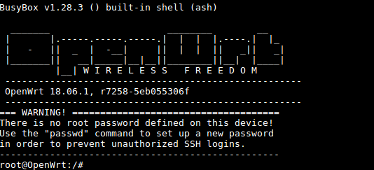
On first boot the system will automatically extend the file system on the TF card to the max capacity:
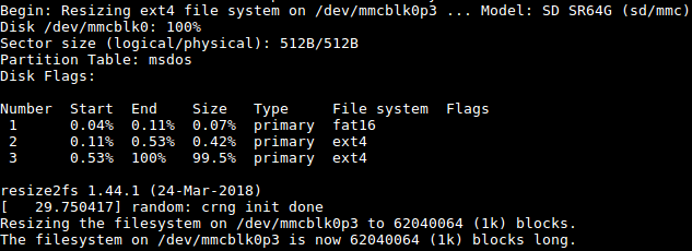
Please wait for this to be done.
- Login via SSH
- Login via Web
You can login OpenWrt via a LuCI Web page.
By default you will login as root without a password, just click on "Login" to login.
1.3 Manage Software Packages
OpenWrt has a package management utility: opkg. You can get its details by running the following command:
$ opkg
Package Manipulation:
        update                  Update list of available packages
        upgrade <pkgs>          Upgrade packages
        install <pkgs>          Install package(s)
        configure <pkgs>        Configure unpacked package(s)
        remove <pkgs|regexp>    Remove package(s)
        flag <flag> <pkgs>      Flag package(s)
         <flag>=hold|noprune|user|ok|installed|unpacked (one per invocation)

Informational Commands:
        list                    List available packages
        list-installed          List installed packages
        list-upgradable         List installed and upgradable packages
        list-changed-conffiles  List user modified configuration files
        files <pkg>             List files belonging to <pkg>
        search <file|regexp>    List package providing <file>
        find <regexp>           List packages whose name or description matches <regexp>
        info [pkg|regexp]       Display all info for <pkg>
        status [pkg|regexp]     Display all status for <pkg>
        download <pkg>          Download <pkg> to current directory
...
These are just part of the manual. Here are some popular opkg commands.
- Update Package List
Before you install a package you'd better update the package list:
$ opkg update
- Check Available Packages
$ opkg list
At the time of writing there are 3241 packages available.
- Check Installed Packages:
$ opkg list-installed
At the time of writing 124 packages have been installed.
- Install/Delete Packages:
$ opkg install <pkgs>
$ opkg remove <pkgs>
- Check Files Contained in Installed Packages:
$ opkg files <pkg>
- Install Chinese Language Package for LuCI
$ opkg install luci-i18n-base-zh-cn
- Check Changed Files:
$ opkg list-changed-conffiles
- Reference Links:
1.4 Check System Status
- Check CPU Temperature & Frequency via Commandline
$ cpu_freq
Aavailable frequency(KHz):
        480000 624000 816000 1008000
Current frequency(KHz):
        CPU0 online=1 temp=26548C governor=ondemand freq=624000KHz
        CPU1 online=1 temp=26548C governor=ondemand freq=624000KHz
        CPU2 online=1 temp=26548C governor=ondemand freq=624000KHz
        CPU3 online=1 temp=26548C governor=ondemand freq=624000KHz
These messages mean that there are four CPU cores working online simultaneously. Each core's temperature is 26.5 degrees in Celsius, the scheduling policy is on-demand and the working frequency is 624MHz. You can set the frequency by running the following command:
$ cpu_freq -s 1008000
Aavailable frequency(KHz):
        480000 624000 816000 1008000
Current frequency(KHz):
        CPU0 online=1 temp=36702C governor=userspace freq=1008000KHz
        CPU1 online=1 temp=36702C governor=userspace freq=1008000KHz
        CPU2 online=1 temp=36702C governor=userspace freq=1008000KHz
        CPU3 online=1 temp=36702C governor=userspace freq=1008000KHz
These messages mean four CPU cores are working online. Each core's temperature is 26.5 degrees. Each core's governor is on demand and the frequency is 480 MHz.
- Check System Status on OpenWrt-LuCI Web Page
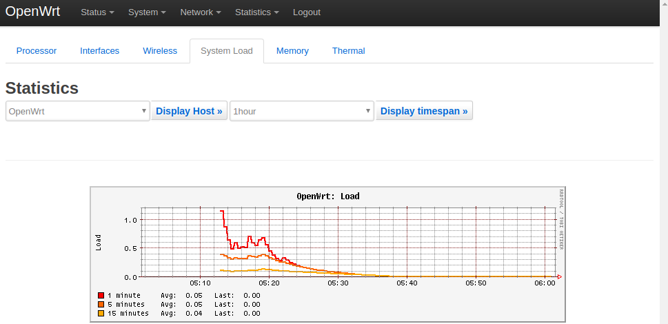
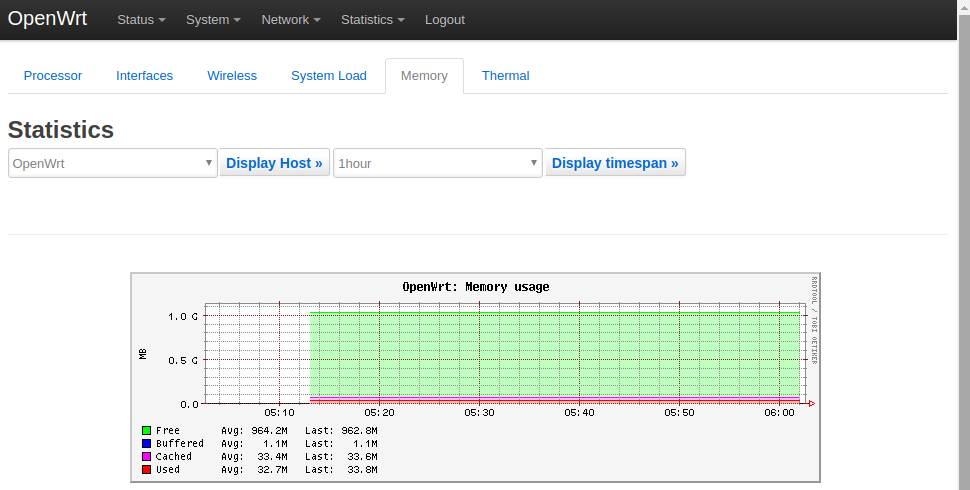
After open the OpenWrt-LuCI page, go to "Statistics ---> Graphs" and you will see various system statistics e.g.:
1) System Load:
2) RAM:
3) CPU Temperature:
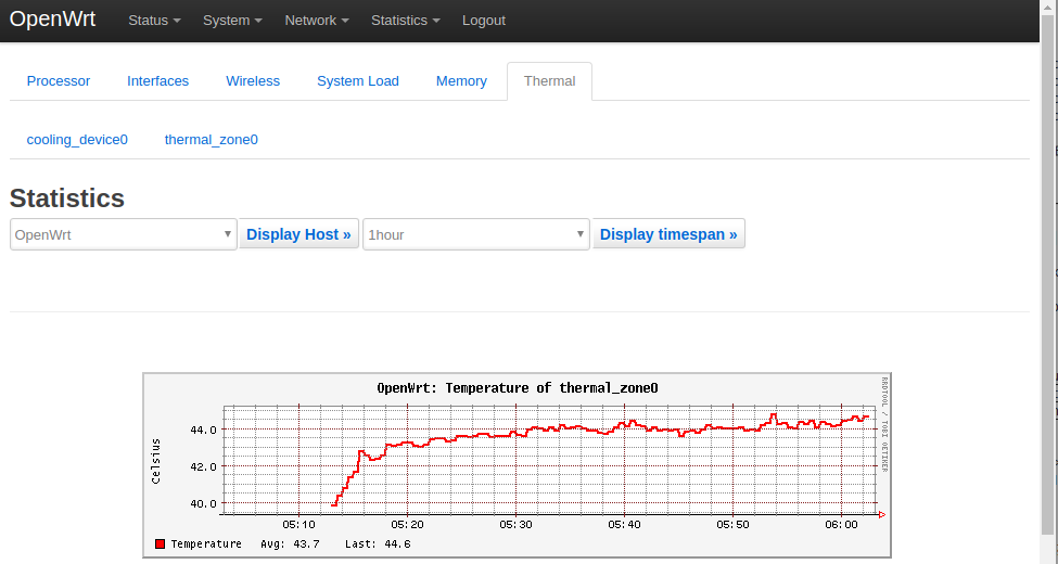
All the statistics listed on the Statistics page are presented by the luci-app-statistics package which uses the Collectd utility to collect data and presents them with the RRDtool utility.
If you want to get more statistics you can install other collectd-mod-* packages.
All collectd-mod-* packages use the same configuration file: /etc/config/luci_statistics.
- Reference Links:
1.5 Check Network->Interfaces Configurations
- After open the OpenWrt-LuCI page, go to "Network" ---> "Interfaces" and you will see the current network's configurations:
- All the configurations listed on the Network->Interfaces page are stored in the "/etc/config/network" file.
1.6 USB WiFi
Currently the NanoPi NEO2 Black only works with a RTL8821CU USB WiFi dongle, plug and play. After this module is connected to the board it will by default work under AP mode and the hotspot's name is "rtl8821cu-mac address" and the password is "password";
1.7 Huawei's WiFi 2 mini(E8372H-155) Module
After this module is connected to the board it will be plug and play. The hotspot's name is "HUAWEI-8DA5". You can connect a device to the internet by connecting to this hotspot.