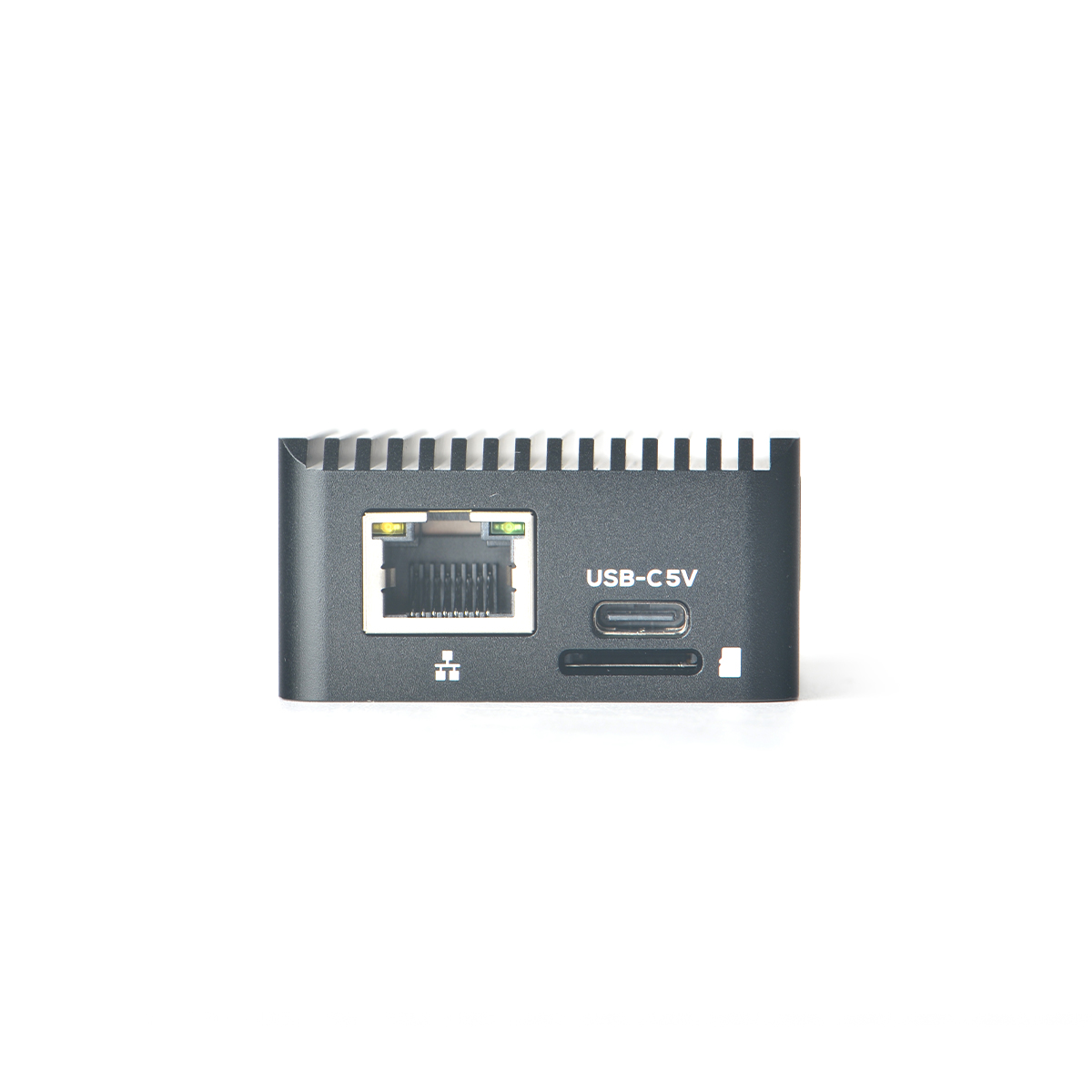
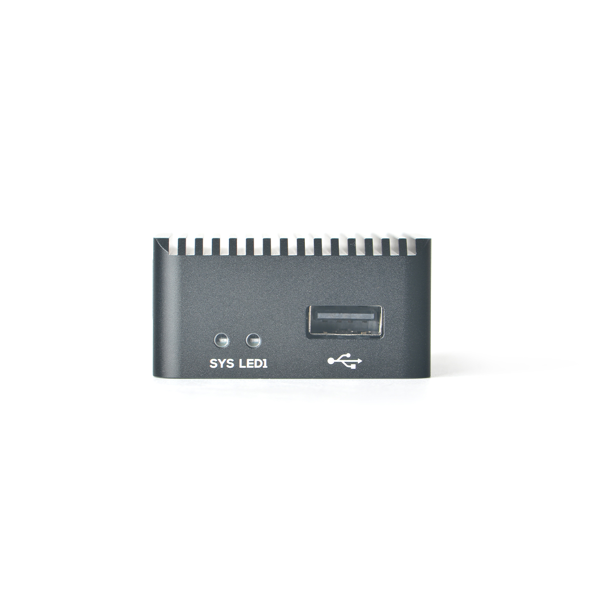
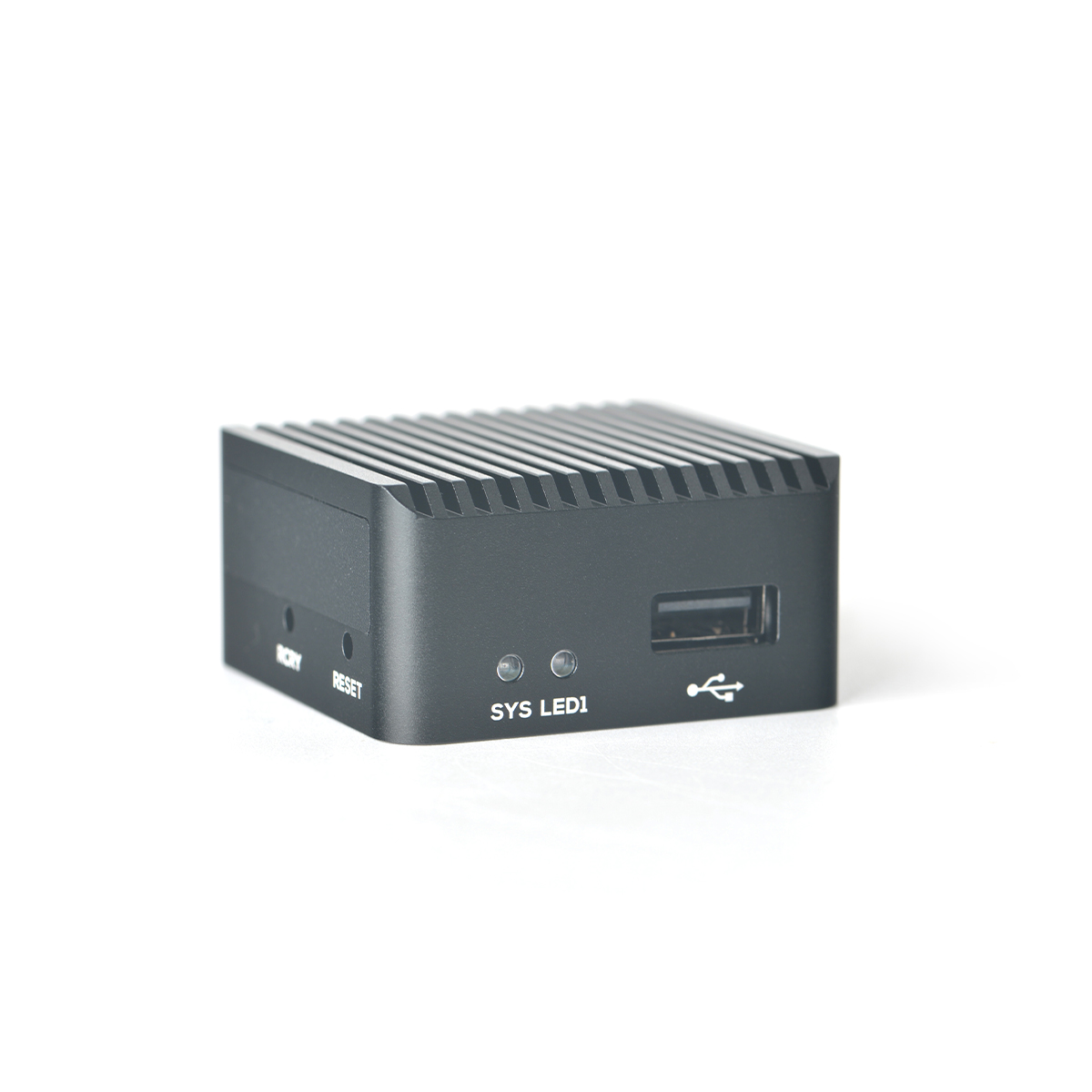
NanoPi Zero2
Contents
- 1 Introduction
- 2 Hardware Spec
- 3 Diagram, Layout and Dimension
- 4 Get Started
- 4.1 Essentials You Need
- 4.2 TF Cards We Tested
- 4.3 Configure parameters for serial port
- 4.4 Install OS
- 5 Work with FriendlyCore
- 6 Work with Debian Core
- 7 How to Compile
- 8 Backup rootfs and create custom SD image (to burn your application into other boards)
- 9 Common Linux-based operating system operations
- 10 Unbricking Method
- 11 Resources
- 12 Update Log
1 Introduction
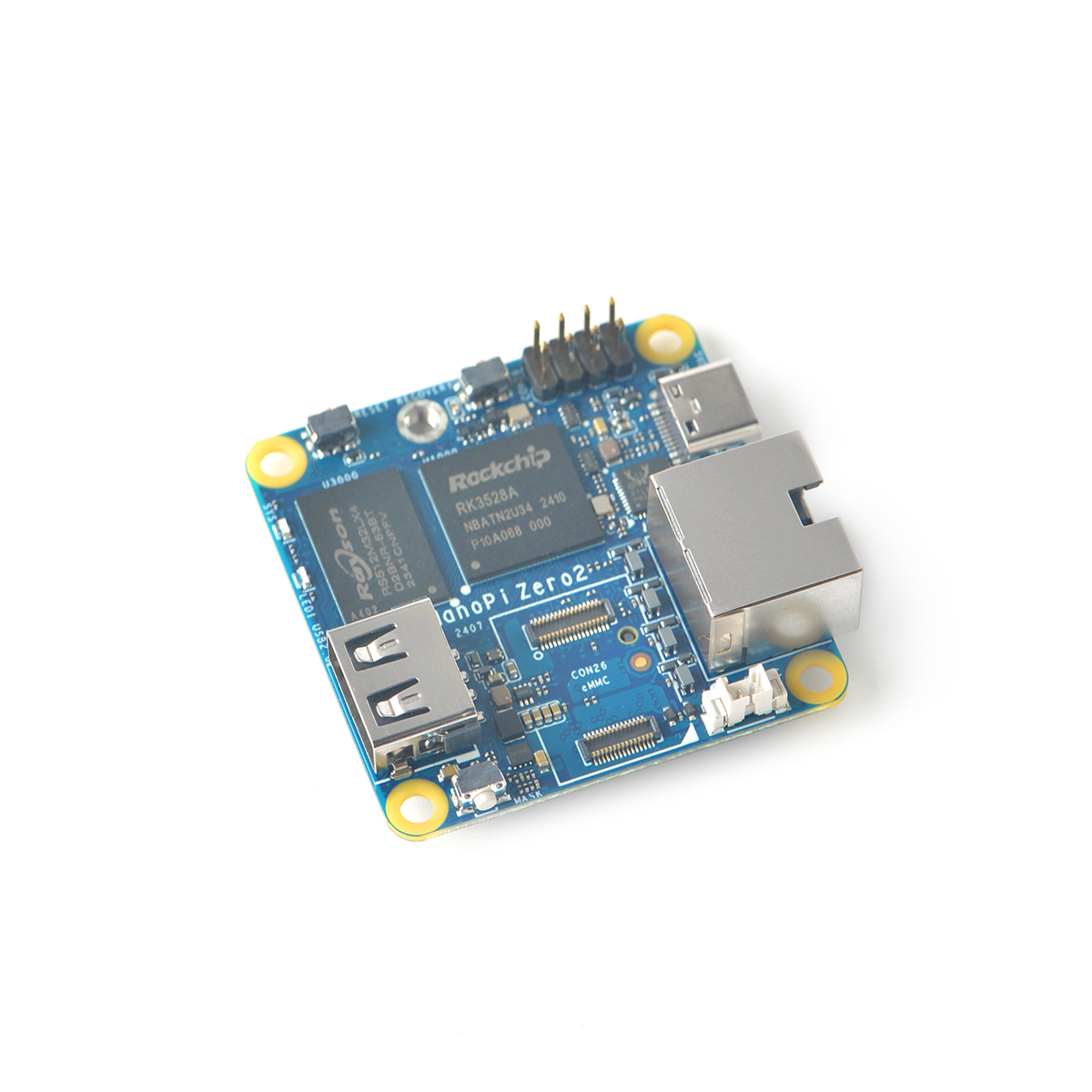
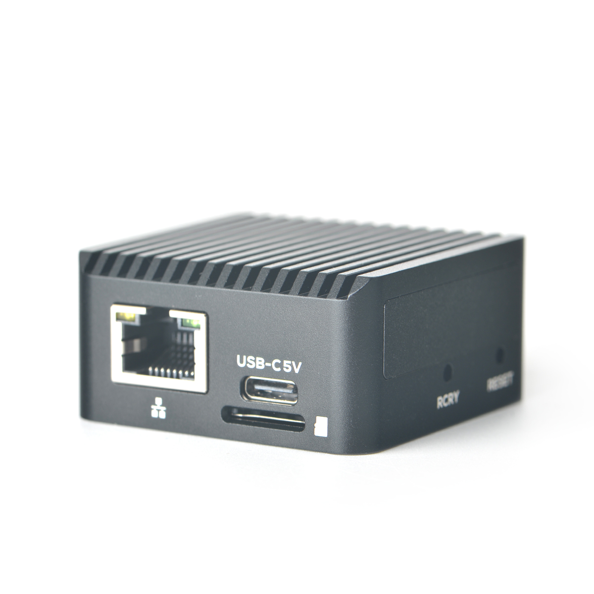
- The NanoPi-Zero2 is another fun board developed by FriendlyELEC for makers, hobbyists and fans.
2 Hardware Spec
- SoC: Rockchip RK3528A
- CPU: Quad-core ARM Cortex-A53
- GPU: ARM Mali-450 GPU
- VPU: 4K H265/H264 60fps decoding
- RAM: 1GB/2GB LPDDR4/LPDDR4X
- Flash: Supports eMMC Module
- Ethernet: one Native Gigabit Ethernet
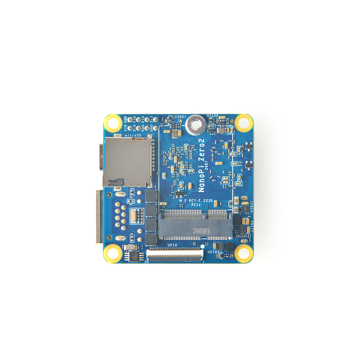
- M.2 Key-E 2230 connector with PCIe 2.1
- USB Ports:
- One USB 2.0 Host Type-A port
- One USB 2.0 Device Type-C port for eMMC upgrade
- One microSD Slot
- One 30-pin FPC GPIO connector
- Debug: Debug UART, 3.3V level, 1500000bps
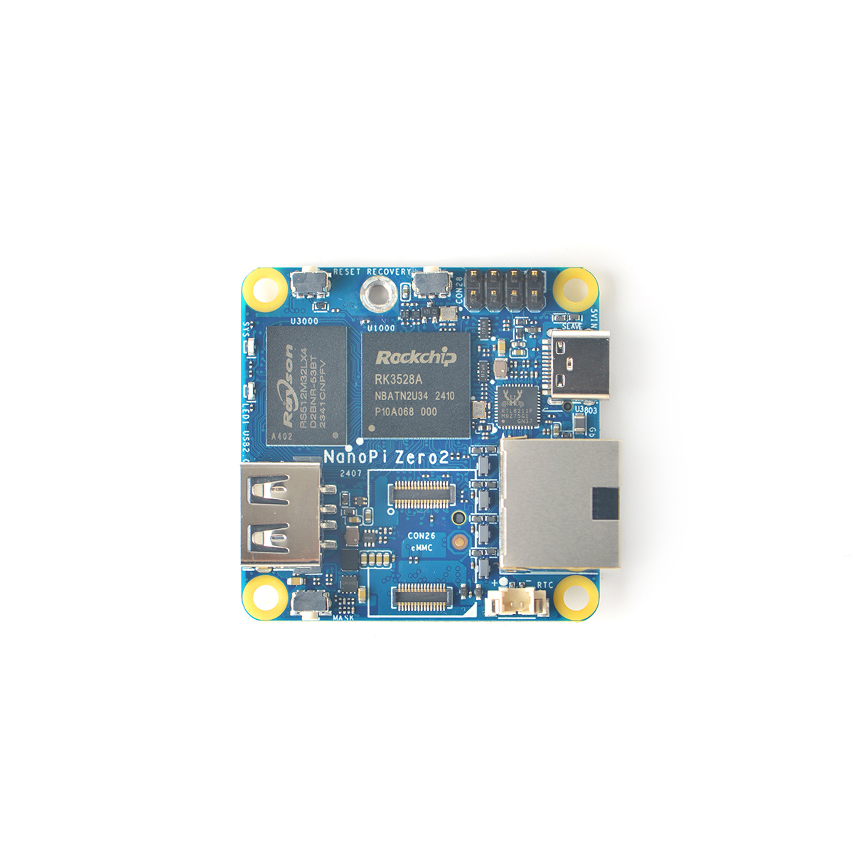
- LEDs: 2 x GPIO Controlled LEDs (SYS & LED1)
- others:
- 2 Pin 1.27/1.25mm battery connector for Low-power RTC
- RESET Button, RECOVERY Button, and MASK Button for eMMC upgrade
- Power supply: DC 5V/2A, via USB-C connector or 2.54mm Header
- PCB Size: 45*45*1.2mm
- Temperature measuring range: 0℃ to 80℃
3 Diagram, Layout and Dimension
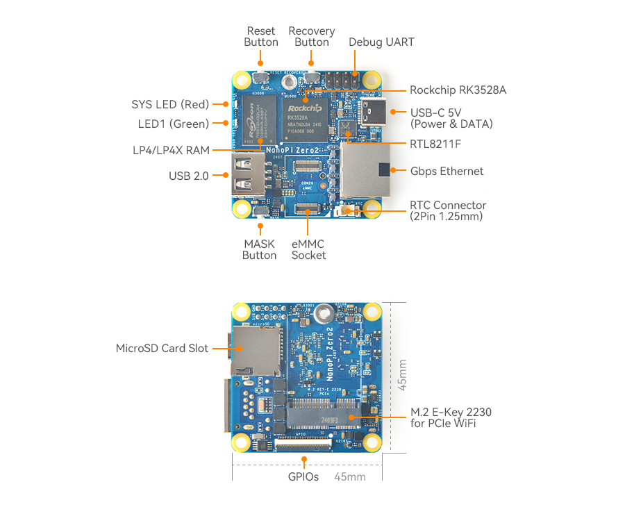
3.1 Layout
- 8-Pin 2.54mm Header & Debug UART Pin Spec
- Debug UART is 3.3V level, 1500000bps
Pin# Assignment Description Pin# Assignment Description 1 GND 0V 2 VCC5V0_SYS 5V power output/input 3 UART2DBG_TX Debug UART TX 4 VCC5V0_SYS 5V power output/input 5 UART2DBG_RX Debug UART RX 6 GND 0V 7 VCC_3V3 3.3V power output 8 GND 0V
- VCC5V0_SYS is connected to USB-C 5V directly.
- VCC_3V3 is system 3.3V power, and shared with M.2 Key-E, eMMC, SD, 30-pin GPIO, Ethernet etc. The maxium output of this pin is 300mA.
- M.2 Key-E
- It has a PCIe 2.1 x1, supports PCIe wifi.
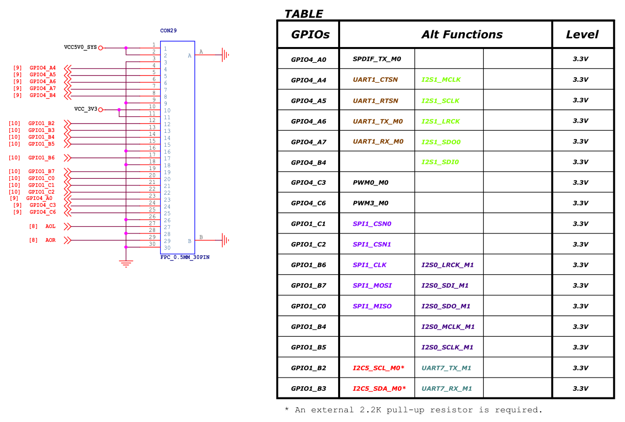
- 30-Pin FPC GPIO
- It is a 0.5mm FPC Connector.
- VCC5V0_SYS is connected to USB-C 5V directly. Don't input 5V Via this Pins.
- VCC_3V3 is system 3.3V power, and shared with M.2 Key-E, eMMC, SD, 30-pin GPIO, Ethernet etc. The maxium output of this pins is 300mA.
- USB Port
- USB 2.0 Type-A port has 0.95A overcurrent protection.
- RTC
- RTC backup current is 0.25μA TYP (VDD =3.0V, TA =25℃).
- Connector P/N: Molex 53398-0271
- Power
- The peak power of this SBC Soc is 5W.
- To estimate the overall power consumption, in addition to the SBC power supply, the eMMC module, M.2 module, USB peripherals, and GPIO board should also be considered.
4 Get Started
4.1 Essentials You Need
Before starting to use your NanoPi-Zero2 get the following items ready
- NanoPi-Zero2
- MicroSD Card/TF Card: Class 10 or Above, minimum 8GB SDHC
- 5V/3A and above USB Type-C interface power adapter
- If you need to develop and compile,you need a computer that can connect to the Internet. It is recommended to install Ubuntu 20.04 64-bit system and use the following script to initialize the development environment, or use docker container:
4.2 TF Cards We Tested
Refer to: TFCardsWeTested
4.3 Configure parameters for serial port
Use the following serial parameters:
| Baud rate | 1500000 |
| Data bit | 8 |
| Parity check | None |
| Stop bit | 1 |
| Flow control | None |
4.4 Install OS
4.4.1 Downloads
4.4.1.1 Official image
Visit download link to download official image files (in the "01_Official images" directory).
The table below lists all official images, the word 'XYZ' in image filename meaning:
- sd: Use it when you need to boot the entire OS from the SD card
- eflasher: Use it when you need to flash the OS to eMMC via TF card
- usb: Use it when you need to flash the OS to eMMC via USB
| Icon | Image Filename | Version | Description | Kernel Version |
|---|---|---|---|---|
| |
rk3528-XYZ-debian-bookworm-core-6.1-arm64-YYYYMMDD.img.gz | bookworm | Debian 12 Core, No desktop environment, command line only | 6.1.y |
| |
rk3528-XYZ-ubuntu-noble-core-6.1-arm64-YYYYMMDD.img.zip | noble | 64-bit Ubuntu image file based on Ubuntu core 24.04 64bit | 6.1.y |
| |
rk3528-XYZ-openmediavault-6.1-YYYYMMDD.img.gz | Shaitan | OpenMediaVault NAS system, base on Debian 12 | 6.1.y |
| |
rk3528-XYZ-friendlywrt-21.02-YYYYMMDD.img.gz | 21.02 | FriendlyWrt, based on OpenWrt 21.02 | 6.1.y |
| |
rk3528-XYZ-friendlywrt-21.02-docker-YYYYMMDD.img.gz | 21.02 | FriendlyWrt with Docker, based on OpenWrt 21.02 | 6.1.y |
| |
rk3528-XYZ-friendlywrt-23.05-YYYYMMDD.img.gz | 23.05 | FriendlyWrt, based on OpenWrt 23.05 | 6.1.y |
| |
rk3528-XYZ-friendlywrt-23.05-docker-YYYYMMDD.img.gz | 23.05 | FriendlyWrt with Docker, based on OpenWrt 23.05 | 6.1.y |
| Other Image | ||||
| |
rk3528-XYZ-multiple-os-YYYYMMDD-25g.img.gz | - | It contains multiple OS image files, making it convenient for testing different operating systems | |
4.4.1.2 Tools (optional)
Visit download link to download tools (in the "05_Tools" directory).
| Filename | Description |
|---|---|
| win32diskimager.rar | This program is designed to write a raw disk image to a removable device or backup a removable device to a raw image file |
| SD Card Formatter | A program (application) that allows easy and quick clear the SD card |
| RKDevTool_Release_v2.84.zip | Rockchip flashing tool, for USB upgrade |
4.4.2 Flashing the OS to the microSD card
Follow the steps below:
- Get an 8G microSD card;
- Visit download linkto download image files (in the "01_Official images/01_SD card images" directory);
- Download the win32diskimager tool (in the "05_Tools" directory), or use your preferred tool;
- Extract the .gz format compressed file to get the .img format image file;
- Run the win32diskimager utility under Windows as administrator. On the utility's main window select your SD card's drive, the wanted image file and click on "write" to start flashing the SD card.
- Take out the SD and insert it to NanoPi-Zero2's microSD card slot;
- Power on NanoPi-Zero2 and it will be booted from your TF card, some models may require pressing the Power button to start;
4.4.3 Install OS to eMMC
4.4.3.1 Option 1: Install OS via TF Card
This method firstly boots a mini Linux from a TF card and then automatically runs an EFlasher utility to install the OS to eMMC. You can connect your system to an HDMI monitor and watch its progress.
This is optional. You can watch its progress by observing its LEDs as well:
Progress |
SYS LED(Red) |
|---|---|
Power On |
Solid On |
System Boot |
Slow Flashing |
Installation in Progress |
Fast Flashing |
Installation Done |
Slow Flashing |
By default, flashing starts automatically upon power-up, so be sure to back up the data in eMMC. If you don't want it to start automatically, you can use image file with a filename containing the words 'multiple-os' and manually select the OS you want to flash on the interface.
4.4.3.1.1 Flash Official OS to eMMC
Follow the steps below:
- Get an SDHC card with a minimum capacity of 8G
- Visit download linkto download image files (in the "01_Official images/02_SD-to-eMMC images" directory) and win32diskimager tool (in the "05_Tools" directory);
- Extract the .gz format compressed file to get the .img format image file;
- Run the win32diskimager utility under Windows as administrator. On the utility's main window select your SD card's drive, the wanted image file and click on "write" to start flashing the SD card.
- Eject your SD card and insert it to NanoPi-Zero2’s microSD card slot.
- Turn on NanoPi-Zero2, it will boot from the SD card and automatically run EFlasher to install the OS to the board’s eMMC.
- After flashing is complete, eject the SD card from NanoPi-Zero2, NanoPi-Zero2 will automatically reboot and boot from eMMC.
4.4.3.1.2 Flash third party OS (Image file) to eMMC
- Auto Install (Default Behavior)
1) Download an “eflasher” firmware from network drive(in the "01_Official images/02_SD-to-eMMC images" directory), extract it and install it to a TF card ;
2) Eject and insert the TF card to your PC, after a “FriendlyARM” device shows up(Under Linux, it is a “FriendlyARM” directory), copy the image file ending with .raw or .gz into the directory (Note: if your file is in .img format, please rename it to .raw format).
3) Open the eflasher.conf file on the TF card, set “autoStart=” to the name of your image file, such as:
autoStart=openwrt-rockchip-armv8_nanopi-ext4-sysupgrade.img.gzIn addition to third-party image, official image files which with the '-sd-' word in the filename are also supported, for example: rk3NNN-sd-friendlywrt-21.02-YYYYMMDD.img.gz
4) Eject the TF card, insert the TF card to NanoPi-Zero2, power it on it will automatically install your firmware. You can watch the installation progress by observing the LEDs’ status.
4.4.3.2 Option 2: Install OS on Web Page
Get a TF card which has been installed with FriendlyWrt, log in FriendlyWrt on the web page, click on “System” ->”eMMC Tools”. Click on “Select file” to select your wanted image file, either an official image (filename containing '-sd-') or a third party image. The file should be a “.gz” or “.img” file.
After a file is selected, click on “Upload and Write” to start installing an OS.
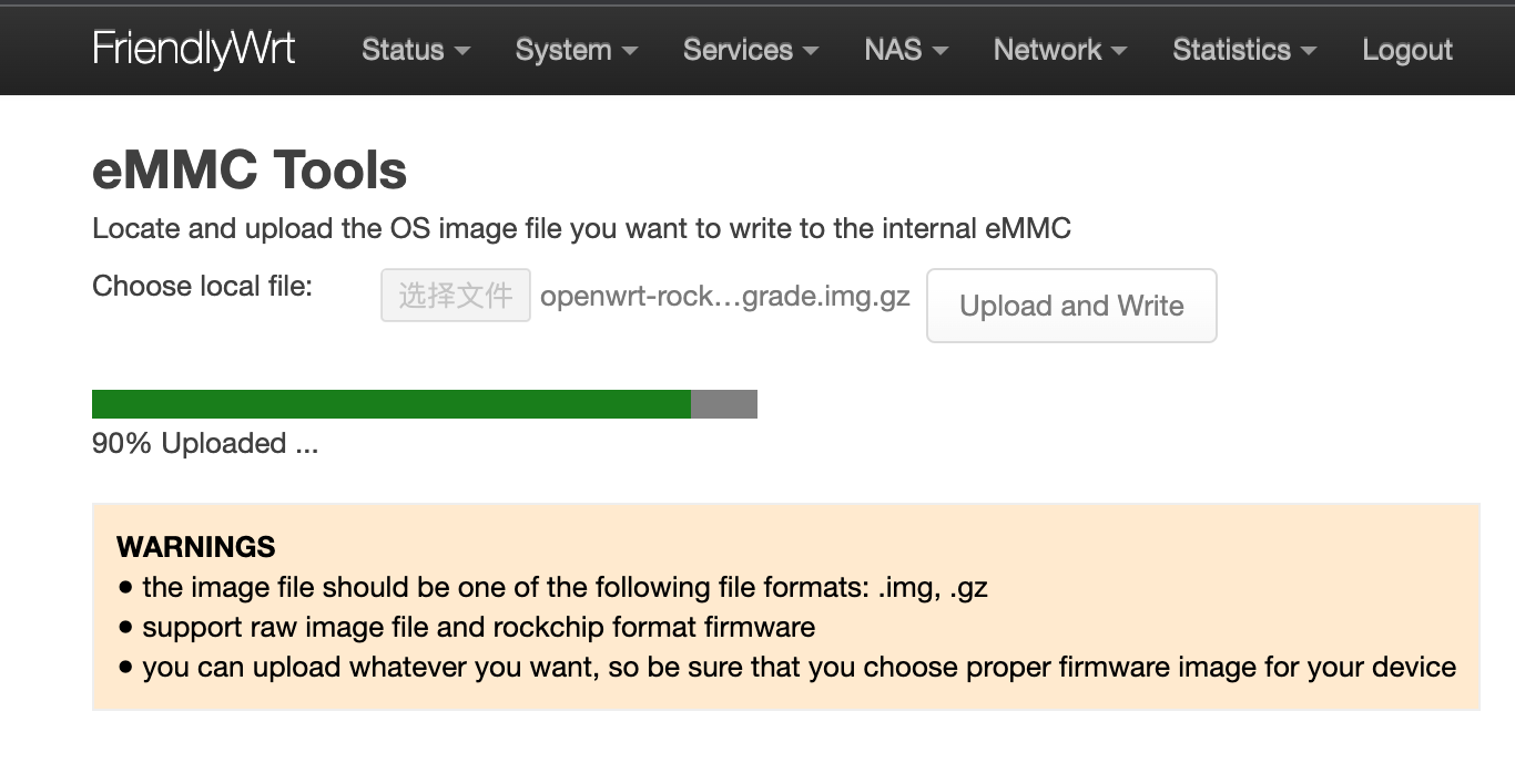
After installation is done, eject the SD card, the system will automatically reboot and load the OS from eMMC. After the OS begins to load, if the system LED is flashing and the network LED is on, it means the the OS has loaded successfully. If the OS is FriendlyWrt, you can click on “Go to Homepage” to enter the homepage.
For official OS, you need select the file with the filename containing '-sd-', for example: rk3NNN-sd-friendlywrt-21.02-YYYYMMDD.img.gz, the compression file only supports the .gz format. If the file is too large, you can compress it into .gz format before uploading.
4.4.3.3 Option 3: Install OS via USB
4.4.3.3.1 Step 1: Install USB Driver and Tools/Utilities
Download a driver file DriverAssitant_v5.12.zip under the “tools” directory from network drive, extract and install it.
Under the same directory, download a utility RKDevTool_Release_v2.84.zip and extract it.
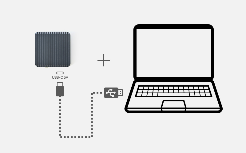
4.4.3.3.2 Step 2: Connect NanoPi-Zero2 to PC and Enter Installation Mode
Press and hold the “Mask” key, Use a USB cable, connect NanoPi-Zero2 to a PC,After the status LED has been on for at least 3 seconds, release the Mask key;
4.4.3.3.3 Step 3: Install image to eMMC
A firmware in general is packaged in either of the two options: the first is an whole image (ie, update.img) which is often offered by third party developers, the second is that an image is packaged and placed in multiple partition images. FriendlyElec offers an image in the latter option.
- Option 1: Install whole image (ie, update.img)
On a PC which has the extracted RKDevTool_Release_v2.84 utility, go to the RKDevTool_Release_v2.84 directory, run the RKDevTool.exe file. If everything works, you will see a “Found a new Maskrom device” message on the utility;
Go to “Upgrade Firmware(升级固件)”, click on “Firmware(固件)”, select your wanted image file, and click on “Upgrade(升级)” to install. After installation is done, your board will reboot automatically and load the system from eMMC;
- Option 2: Install OS that is packaged & placed in multiple partition images
Go to network drive to download your needed package and extract it (in the "01_Official images/03_USB upgrade images).
After it is extracted, you will see some utilities and a configuration file under the directory. double click on RKDevTool.exe, you will see a “Found a new Maskrom device” message on the utility. Click on the “Execute”, wait a moment and it will be installed. After installation is done your system will automatically reboot and load the system from eMMC.
5 Work with FriendlyCore
5.1 FriendlyCore User Account
- Non-root User:
   User Name: pi
   Password: pi
- Root:
   User Name: root
   Password: fa
5.2 Update Software Packages
$ sudo apt-get update
5.3 Setup Network Configurations
5.3.1 Set static IP address
By default "eth0" is assigned an IP address obtained via dhcp. If you want to change the setting you need to change the following file:
vi /etc/network/interfaces.d/eth0
For example if you want to assign a static IP to it you can run the following commands:
auto eth0
iface eth0 inet static
    address 192.168.1.231
    netmask 255.255.255.0
    gateway 192.168.1.1
5.3.2 Set a DNS
You also need to modify the following file to add the DNS configuration:
vi /etc/systemd/resolved.conf
For example, set to 192.168.1.1:
[Resolve]
DNS=192.168.1.1
Restart the systemd-resolved service with the following command:
sudo systemctl restart systemd-resolved.service
sudo systemctl enable systemd-resolved.service
5.3.3 Set up to use another network interface
To change the setting of "eth1" you can add a new file similar to eth0's configuration file under the /etc/network/interfaces.d/ directory.
5.4 Setup Wi-Fi
First, use the following command to check if Network-Manager is installed on your system:
which nmcliIf you have installed it, refer to this link to connect to WiFi: Use NetworkManager to configure network settings, If you do not have Network-Manager installed on your system, please refer to the following method to configure WiFi,
By default the WiFi device is "wlan0". You need to create a configuration file under "/etc/network/interfaces.d/" for WiFi:
vi /etc/network/interfaces.d/wlan0
Here is a sample wlan0 file:
auto lo
iface lo inet loopback
auto wlan0
iface wlan0 inet dhcp
wpa-driver wext
wpa-ssid YourWiFiESSID
wpa-ap-scan 1
wpa-proto RSN
wpa-pairwise CCMP
wpa-group CCMP
wpa-key-mgmt WPA-PSK
wpa-psk YourWiFiPassword
Please replace "YourWiFiESSID" and "YourWiFiPassword" with your WiFiESSID and password. After save and close the file you can connect to your WiFi source by running the following command:
sudo systemctl daemon-reload
sudo systemctl restart networking
After you power on your board it will automatically connect to your WiFi source.
Please note that if you use one TF card to boot multiple boards the WiFi device name will likely be named to "wlan1", "wlan2" and etc. You can reset it to "wlan0" by deleting the contents of the following file and reboot your board:
/etc/udev/rules.d/70-persistent-net.rules
5.5 Install the kernel-header package
sudo dpkg -i /opt/linux-headers-*.deb
6 Work with Debian Core
6.1 Account & Password
Regular Account:
User Name: pi
Password: pi
Root:
the root user account is disabled by default, you may configure the root password through the 'sudo passwd root' command.
6.2 View IP address
Since the Debian Bullseye hostname is the hardware model by default, you can use the ping command to get the IP address:ping NanoPi-Zero2
Debian Bullseye uses network-manager to manage the network, and the network ports are configured to automatically obtain IP addresses by DHCP (including devices with multiple network ports).
6.3 Connect to Debian via SSH
Run the following commandssh pi@NanoPi-Zero2
The default password is: pi
6.4 Update Software Packages
$ sudo apt-get update
6.5 Change time zone
6.5.1 Check the current time zone
timedatectl
6.5.2 List all available time zones
timedatectl list-timezones
6.5.3 Set the time zone (e.g. Shanghai)
sudo timedatectl set-timezone Asia/Shanghai
6.6 Change startup LOGO
Replace the following two files in the kernel source code directory and recompile the kernel:
kernel/logo.bmp
kernel/logo_kernel.bmp
Or use the script to operate, as shown below:
- Download scripts:
git clone https://github.com/friendlyarm/sd-fuse_rk3399.git -b kernel-4.19 --single-branch
cd sd-fuse_rk3399
- Compile kernel and repackage firmware
convert files/logo.jpg -type truecolor /tmp/logo.bmp
convert files/logo.jpg -type truecolor /tmp/logo_kernel.bmp
sudo LOGO=/tmp/logo.bmp KERNEL_LOGO=/tmp/logo_kernel.bmp ./build-kernel.sh debian-bookworm-core-arm64
sudo ./mk-sd-image.sh debian-bookworm-core-arm64
sudo ./mk-emmc-image.sh debian-bookworm-core-arm64
6.7 Soft Factory Reset
Execute the following command in a terminal:
sudo firstboot && sudo reboot
6.8 Install Docker on Debian
Please refer to: How to Install Docker on Debian
7 How to Compile
Coming soon
8 Backup rootfs and create custom SD image (to burn your application into other boards)
8.1 Backup rootfs
Run the following commands on your target board. These commands will back up the entire root partition:
sudo passwd root
su root
cd /
tar --warning=no-file-changed -cvpzf /rootfs.tar.gz \
    --exclude=/rootfs.tar.gz --exclude=/var/lib/docker/runtimes \
    --exclude=/etc/firstuser --exclude=/etc/friendlyelec-release \
    --exclude=/usr/local/first_boot_flag --one-file-system /
Note: if there is a mounted directory on the system, an error message will appear at the end, which can be ignored.
8.2 Making a bootable SD card from a root filesystem
Only support RK3328/RK3399/RK3568/RK3566/RK3588
9 Common Linux-based operating system operations
9.1 Using ADB on Linux Systems
9.1.1 Enabling ADB in Buildroot System
Enable on Startup
mv /etc/init.d/K50usbdevice /etc/init.d/S50usbdevice
reboot
Enable Temporarily
usbdevice-wrapper start
9.1.2 Enabling ADB in Ubuntu and Debian Systems
Enable on Startup
sudo systemctl enable usbdevice
sudo reboot
Enable Temporarily
usbdevice-wrapper start
9.1.3 How to Connect
When using ADB, the port connected to the computer is the same as the USB flashing port.
9.2 Install Kernel Headers
sudo dpkg -i /opt/archives/linux-headers-*.deb
10 Unbricking Method
If the ROM is not installed correctly, causing the development board to become bricked, and you might not have the opportunity to reinstall the ROM via an SD card, you need to enter Maskrom mode to unbrick it by erasing the storage device.
10.1 Windows Users
10.1.1 Download Required Files
- Get the necessary tools: Visit here, find RKDevTool_v3.19_for_window.zip and DriverAssitant_v5.12.zip in the 05_Tools directory, and download them to your local machine.
- Install Rockchip USB driver and RKDevTool: Extract DriverAssitant_v5.12.zip to install the Rockchip USB driver, and extract RKDevTool_v3.19_for_window.zip to obtain the Rockchip flashing tool RKDevTool.
- Get the loader: Visit here, enter the tools directory corresponding to your CPU model, and download MiniLoaderAll.bin.
10.1.2 Enter Maskrom Mode to Erase the Storage Device
- Connect NanoPi-Zero2 to your computer using a USB data cable.
- Start RKDevTool on your computer.
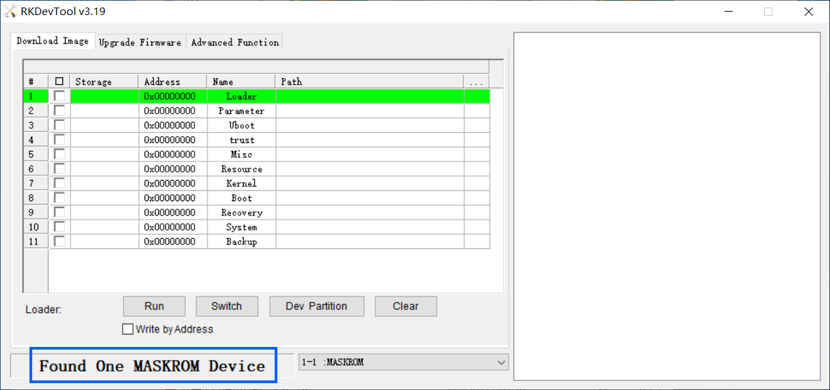
- Disconnect the power from NanoPi-Zero2, hold down the MASK button, connect the power, and release the button when you see Found One MASKROM Device displayed at the bottom of the interface, as shown below:
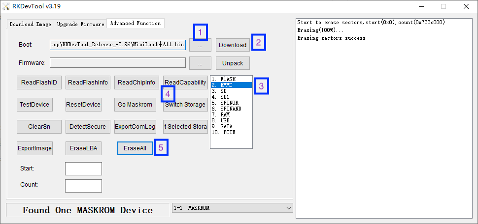
- Click the Advanced Function tab in the RKDevTool interface.
- In the Boot text box, select MiniLoaderAll.bin, then click the Download button.
- Select EMMC, click Switch Storage, then click the EraseAll button to erase the eMMC.
- At this point, NanoPi-Zero2 is restored to its initial state and can be normally booted via SD card or eMMC.
10.2 Linux/Mac Users
10.2.1 Download the Required Files
- Get the necessary tools: Visit here and find upgrade_tool_v2.30_for_linux.tgz (or for Mac users, select upgrade_tool_v2.25_for_mac.tgz) in the 05_Tools directory and download it locally.
- Get the loader: Visit here, enter the tools directory corresponding to your CPU model, and download MiniLoaderAll.bin.
10.2.2 Installation for upgrade_tool
The following commands are for Linux, with only slight differences in file and directory names for Mac users:
tar xzf upgrade_tool_v2.30_for_linux.tgz
cd upgrade_tool_v2.30_for_linux
sudo cp upgrade_tool /usr/local/sbin/
sudo chmod 755 /usr/local/sbin/upgrade_tool
10.2.3 Enter Maskrom Mode to Erase the Storage Device
- Connect NanoPi-Zero2 to the computer using a USB data cable.
- Disconnect the power from NanoPi-Zero2, hold down the MASK button, connect the power, and release the button after 4 seconds.
- Check the connection with the following command:
upgrade_tool LD
A result similar to "DevNo=1 Vid=0x2207,Pid=0x350b,LocationID=13 Mode=Maskrom SerialNo=" indicates that the device has been detected.
- Erase the eMMC with the following command:
upgrade_tool EF MiniLoaderAll.bin
- At this point, NanoPi-Zero2 has been restored to its initial state and can boot the system normally via SD card or eMMC.
11 Resources
11.1 Datasheets and Schematics
- Schematic: NanoPi_Zero2_2407_SCH.pdf
- PCB CAD File:NanoPi_Zero2_2407_DXF.zip
- RK3528A Datasheet:Rockchip_RK3528A_Datasheet_V1.2-20240410.pdf
12 Update Log
12.1 2024-09-04
Initial Release
